

Shure M62V User Guide
222 HARTREY AVE., EVANSTON.
AREA CODE 312/328-9000 . CABLE: SHUREMICRO
@
IL.
60204 U.S.A.
MODEL M62V AUDIO LEVEL CONTROLLER
SHEET
I
DATA
MODEL M62V
AUDIO LEVEL CONTROLLER
1
GENERAL:
The "Level-Loc" Audio Level Controller is basically a
low-noise preamplifier with unity gain from the microphone level input to the microphone level output or
60 dB of voltage gain from the high-impedance microphone level input to the auxiliary level output. The
input and microphone level output contain matching
transformers so either high- or low-impedance operation may be selected. In addition, a high-impedance
auxiliary output is provided capable of driving any
high-impedance amplifier, mixer or tape recorder input
requiring 1 volt or less. This preamplifier has the additional capability of reducing its gain as the input
signal increases, thereby holding the output signal
constant. After a predetermined input level threshold
is reached the output level is "locked", that is, it
remains constant even if the input signal increases
by as much as 100 times (40 dB). This reduction in
gain, which results in a constant output level, is
obtained without introducing significant distortion or
transients into the program material. The DISTANCE
SELECTOR switch determines the input level at which
gain reduction (Level-Loc action) begins. An INPUT
LEVEL control is also provided that:
1. Can be used as a vernier control to allow fine
adjustment of input threshold between the preset
threshold levels selected by the DISTANCE
SELECTOR switch.
2. Can act as an input attenuator for signals that
are higher than normal microphone levels. Such
inputs may be: signals from microphones used
very close to the mouth, outputs from preamplifiers, line amplifiers, tuners or tape recorders.
The Audio Level Controller:
Reduces blasting or large volume increases
when a speaker or entertainer varies his distance and position from the microphone.
Upgrades tape-recording systems and the Audio
portion of Video Tape Recorders, by controlling
the maximum signal level being fed to the recorder. This prevents distortion and overloading
of the tape recorder which might be caused by
"close talking" the microphone, or by very loud
vocal or musical passages.
-
Permits any number of microphones to be used
in
a paging system or conference arrangement,
without setting the level for each individual
microphone. (For paging systems only
dance microphones with normally open switches
should be used.) Any number of these microphones may be operated in parallel across the
low-impedance input of the
Level Controller will automatically set a fixed
maximum paging level that cannot be exceeded.
M62V, the Audio
SPECIFICATIONS
lnput lmpedance
High Impedance: 50 kilohms
Low Impedance: 300 ohms (for 25 to 600 ohm
lnput Levels:
High Impedance: Microphone level to 10 volts
Low Impedance: Microphone level to
Output Impedance:
High lmpedance Microphone Level:
Minimum recommended load:
Low lmpedance Microphone Level: Less than 50
ohms
Minimum recommended load:
Aux. Output: 10 kilohms
Minimum recommended load: 10 kilohms
Gain Characteristics:
control maximum (10) DISTANCE SELECTOR in
"18" or More" position; measured from input to
output]
INPUT
Hi Imp. Mic.
Lo Imp. Mic.
Frequency Response:
i2 dB 40 to 20,000
(below threshold):
sources)
max. (using INPUT LEVEL
control)
max. (using INPUT LEVEL
control)
5
I Below threshold, INPUT LEVEL
OUTPUT
Hi
Imp.
Mic.
Unity
+20 dB
Hz
Lo
Imp.
Mic.
-20 dB
Unity
3.3
kilohms
25
ohms
Aux.
+60 dB
+80 dB
low-impe-
.2 volt
kilohms
Output
Copyright
27A823 (PC)
1976,
Shure
Brothers
Inc.
Printed
in
U.S.A.
Maximum Output Noise
PUT, in dB below
1 volt):
(HI IMPEDANCE MIC. OUT-
300-20.000
(Noise)
Hz
30-20,000
(Hum
Lo Imp. lnput
150 ohm Termination -103 dB -95 dB
Hi Imp. lnput
33
kilohm Termination -104 dB -95 dB
Distortion
3%
Dynamic Characteristics:
(any level of regulation):
maximum THD
Fast attack, moderate re-
covery, fixed.
Attack: For a 20 dB step increase above thres-
hold, gain is within 2 dB of final value in
500 microseconds.
Recovery: For a 20 dB step decrease to thres-
hold, gain is within 2 dB of final value
in 700 milliseconds.
Battery Life:
Dimensions:
Net Weight:
Approximately 200 hours
See Figure
1
kg (2.2 Ib)
5.
and
Hz
Noise)
switch above the receptacle. This output is designed
to work into a 25- to 600-ohm microphone line or
a
microphone input, or into
high-impedance amplifier
or tape recorder microphone input. The receptacle
is a professional three-pin male audio connector.? See
Figure 2B for microphone level output receptacle connections.
SHIELD
.
-. .
- -
-
-
,T
18
I /
j
-.........
MIC.
OUTPUT
HIGH
IMPEDANCE
MICROPHONE
OUTPUT
MIC
OUTPUT
PLUG
IBALANCEO
CONNECTIONS
LOW
IMPEDkNCE
LINE)
A,,
FIGURE 28
The receptacle marked AUX. OUTPUT is a phono
pin jack which accepts a standard phono pin plug.
This output is designed to work into a high-impedance
(10 kilohms or greater), high-level input of a mixer,
preamplifier, amplifier, or tape recorder. This output
may be connected to the AUX. INPUT of an M68 Series
Mixer, the HIGH-LEVEL INPUT of an M63 Audio Master
or the
LINE INPUT (bridging) of an M67 Professional
Microphone Mixer.
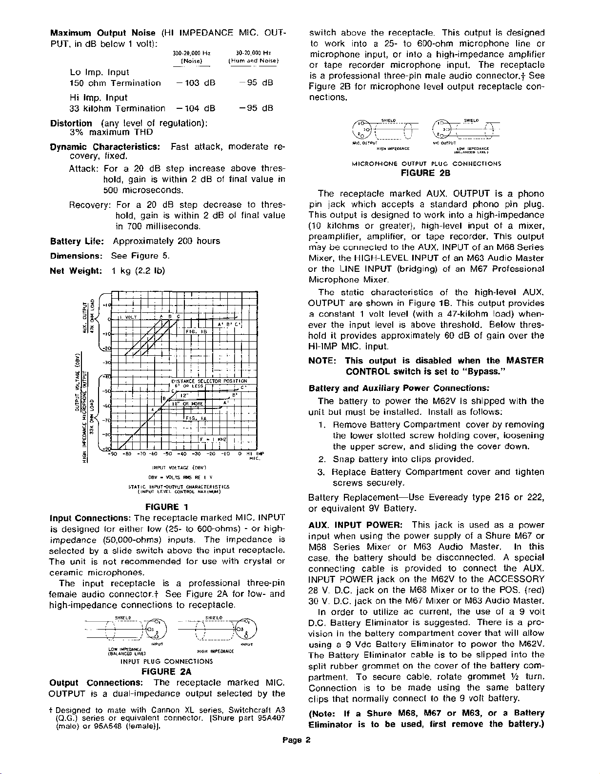
The static characteristics of the high-level AUX.
OUTPUT are shown in Figure
a constant
1 volt level (with a 47-kilohm load) when-
IB. This output provides
ever the input level is above threshold. Below threshold it provides approximately 60 dB of gain over the
HI-IMP MIC. input.
NOTE: This output is disabled when the MASTER
CONTROL switch is set to "Bypass."
-90 -80 -70 -60 -50 -40 -30 -20 -10 0
3
I
lnput Connections:
INPUT VOLTAGE
-
DBV
STATIC INPUT-OUTPUT CHARACTERISTICS
(INPUT LEVEL CONTROL
FIGURE
The receptacle marked MIC. INPUT
VOLTS
RM5
1
(DBV)
RE I V
MAXIMUH)
is designed for either low (25- to 600-ohms)
HI
IMP
MIC.
-
or high-
impedance (50,000-ohms) inputs. The impedance is
selected by a slide switch above the input receptacle.
The unit is not recommended for use with crystal or
ceramic microphones.
The input receptacle is a professional three-pin
female audio connector.? See Figure 2A for low- and
high-impedance connections to receptacle.
.
.-
-
-
--
-.
-..
LOW IMPEDANCE
(BALANCED
INPUT
INPUT INPUT
LINE)
PLUG
CONNECTIONS
HIGH
IMPEDANCE
FIGURE 2A
Output Connections:
The receptacle marked MIC.
OUTPUT is a dual-impedance output selected by the
Designed to mate with Cannon
(Q.G.)
series or equivalent connector.
(male)
or
95A548
(female)].
XL
series, Switchcraft
[Shure part
A3
95,4407
Battery and Auxiliary Power Connections:
The battery to power the M62V is shipped with the
unit but must be installed. Install as follows:
1. Remove Battery Compartment cover by removing
the lower slotted screw holding cover, loosening
the upper screw, and sliding the cover down.
2. Snap battery into clips provided.
3.
Replace Battery Compartment cover and tighten
screws securely.
Battery Replacement-Use
or equivalent
9V Battery.
AUX. INPUT POWER:
Eveready type 216 or 222,
This jack is used as a power
input when using the power supply of a Shure M67 or
M68 Series Mixer or M63 Audio Master. In this
case, the battery should be disconnected.
connecting cable is provided to connect the AUX.
INPUT POWER jack on the
M62V to the ACCESSORY
28 V. D.C. jack on the M68 Mixer or to the POS. (red)
30 V. D.C. jack on the M67 Mixer or M63 Audio Master.
In order to utilize ac current, the use of a 9 volt
D.C. Battery Eliminator is suggested. There is a provision in the battery compartment cover that will allow
9
using a
Vdc Battery Eliminator to power the M62V.
The Battery Eliminator cable is to be slipped into the
split rubber grommet on the cover of the battery compartment. To secure cable, rotate grommet
Connection is to be made using the same battery
clips that normally connect to the 9 volt battery.
(Note:
Shure
M683
M67
Or
M63r
Or
If
a
Eliminator is to be used, first remove the battery.)
Page
2
A special
Y2
turn.
a
Battery
 Loading...