

Page 1
I
@
AREA CODE
TWX:
910- 231-004s
3121866-2200
CABLE: SHUREMICRO
TELEX:
72.4381
'
I
SiiEET
M615AS-2E EQUALIZATION
ANMYzEn SYSTEM
I
The Shure Model M615AS Equalization Analyzer System is designed to permit rapid and accurate adjustment
of the frequency response of a sound reinforcement,
monitoring, or playback system incorporating an equalizer such as the Shure Model
M610 Feedback Controller. The
M615 Equalization Analyzer,
their various accessories, and a portable case. (The M615
ES615 are also available separately.)
and
The M615 provides two major functions. First, it is a
source of equal-energy-per-octave random noise ("pink
noise"), available at microphone and auxiliary levels with
adjustable output, to serve as a test signal source. Second, the M615 accepts the output of the
Microphone (or other microphone) or an auxiliary-level
signal, and indicates the relative energy in each of 10
octave bands. Two light-emitting diodes (LEDs) for each
octave indicate whether the energy is below a given LO
(reference) level, above an adjustable HI level, or (if both
LEDs are off) between the two levels (within the enve-
lope). The object is to adjust the sound system equalizer
to turn off the LEDs of the
system response which is within the envelope. With
minimum envelope size (2 dB) and all LEDs off, the resultant octave-energy frequency response curve will be
smooth within approximately
curves may be selected: flat, or the 3 dB per octave
rolloff above 1 kHz typical of most desired "house curve"
responses. Two overload LEDs, a microphone input
tenuator, and an input level control are also provided. A
switch provides either microphone input low-frequency
response compensation for the
phone or a flat frequency response characteristic.
ES615 Analyzer Microphone is an omnidirectional,
The
dynamic, measurement microphone. Its broad, flat frequency response with controlled low-frequency
designed specifically for use with the M615 Analyzer.
M615AS includes a microphone cable, swivel
The
adapter, tilt bracket,
tem carrying case.
The Model
is identical to the Model
the Model M615-2E Equalization Analyzer instead of the
Model
the
(switch-selectable).
M615. The M615 operates from 108-132 Vac and
M615-2E operates from 90-125 or 180-250 Vac
M615AS-2E Equalization Analyzer System
GENERAL
SR107 Audio Equalizer or
M615AS consists of the
ES615 Analyzer Microphone,
ES615 Analyzer
M615, thereby producing a
k1 dB. Two resultant
at-
ES615 Analyzer Micro-
rolloff is
test/interconnecting cable and sys-
M615AS, except that it contains
The M615 (only) is listed by Underwriters' Laboratories,
Inc., and listed by Canadian Standards Association as
certified.
Model
M615AS Features:
Permits rapid and accurate adjustment of octave
band equalizers in sound systems
Pink noise generator with microphone- or aux-level
output
Ten octave bands from 32 Hz to 16 kHz
Rugged LED High and Low indicators
Selectable resultant octave-energy curve: flat for near
field equalization or 3 dB per octave
1 kHz for reverberant field equalization
LED microphone and input overload indicators to as-
sure accurate equalization
Adjustable input and pink noise output levels
Microphone input with
15 dB attenuator and
selector switches
Adjustable envelope from 2 to 12
Aux output jack for monitoring or connection to ac-
cessory instrumentation
Tilt bracket permits positioning Analyzer at con-
venient viewing angle
Sturdy carrying case for all System components
high/low impedance selectors,
flat/ES615 frequency response
rolloff above
(+I to 26) dB
SPECIFICATIONS
All signal levels referred to are pink noise levels.
Inputs
IMPEDANCE LEVEL CONNECTOR
High or Low MIC 3-pin professional female*
High
Outputs
IMPEDANCE LEVEL CONNECTOR
Pink Noise Generator
High or Low MIC 3-pin professional male'
Pink Noise Generator
High AUX phone and phono pin jacks
Analyzer
High AUX phono pin jack
Designed to mate with Cannon XL series, Switchcraft A3 (Q.G.) series or
equivalent connector
EQUALIZATION ANALYZER
AUX phone and phono pin jacks
Copyright
27A1350 (RB)
1978, Shure Brothers Inc.
Printed in
U.S.A.
Page 2
PINK NOISE GENERATOR
Output Level
AUX LEVEL HI-Z MIC LEVEL
-
1 dBV (890 mV)
(Level control at 10)
LO-Z
-29 dBV (35 mV) -49 dBV (3.5 mV)
MIC LEVEL
Spectrum
Equal energy per octave pink noise, flat %I dB, 32 Hz
to 16 kHz
lmpedance
OUTPUT DESIGNED FOR USE WITH ACTUAL
Lo-Imp.
Mic Level 25- to 600-ohm microphone 110 ohms
Hi-Imp.
Mic Level 33-kilohm microphone circuits 2.3 kilohms
Aux Level High-impedance (10 kilohms 1.5 kilohms
circuits balanced
unbalanced
or more) unbalanced aux unbalanced
circuits
ANALYZER
Sensitivity
(Pink noise levels to turn off LO LEDs; INPUT LEVEL
control fully clockwise)
INPUT 15
Lo-Imp. Mic. Out -117
Hi-Imp. Mic. Out
AUX
dB
ATTENUATOR PRESSURE USING In
In
In -77 dBV (0.14 mV)
-
INPUT VOLTAGE SOUND Hi-Imp. Mic. Out -17 dBV (0.14V)
ES615 MICROPHONE
dBV (1.4 pV) 45 dB SPL
-
102 dBV
(8
-
92 d BV (25 pV)
-
62
pV) 60 dB SPL
dBV (0.79 mV)
-
-
-
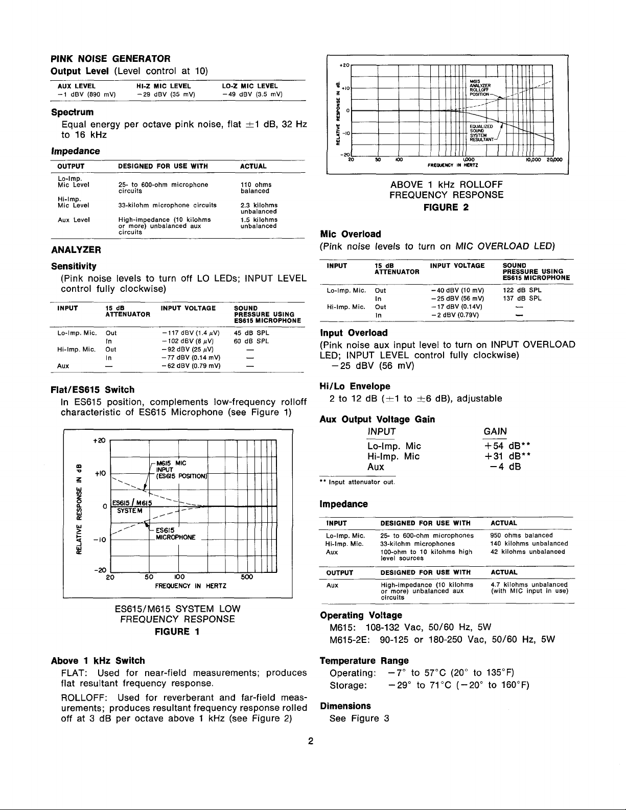
ABOVE 1 kHz ROLLOFF
FREQUENCY RESPONSE
FIGURE 2
Mic Overload
(Pink noise levels to turn on MIC OVERLOAD LED)
INPUT
LO-imp.
15
d~
ATTENUATOR PRESSURE USING
Mic. out -40
In -25
INPUT
VOLTAGE
~BV
(10 mv) 122 d~ SPL
dBV (56 mV) 137 dB SPL
-
2 dBV (0.79V)
SOUND
~~615
MICROPHONE
-
-
lnput Overload
(Pink noise aux input level to turn on INPUT OVERLOAD
LED; INPUT LEVEL control fully clockwise)
dBV (56 mV)
-25
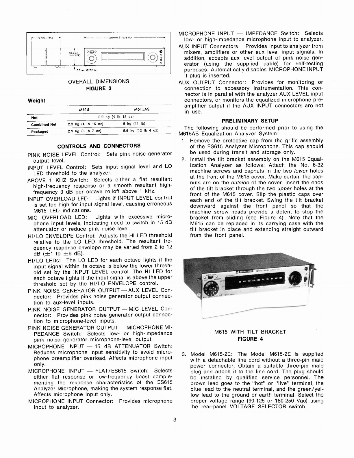
FlatlES615 Switch
In ES615 position, complements low-frequency rolloff
characteristic of ES615 Microphone (see Figure 1)
t20
m
+I0
z
W
V)
5
%
0
Y
W
E
-10
Y
-20
20
Above 1
kHz
FLAT: Used for near-field measurements; produces
flat resultant frequency response.
ROLLOFF: Used for reverberant and far-field meas-
urements; produces resultant frequency response rolled
off at 3
dB
50
100
FREQUENCY IN
HERTZ
500
ES615/M615 SYSTEM LOW
FREQUENCY RESPONSE
FIGURE 1
Switch
per octave above 1 kHz (see Figure
2)
HiILo Envelope
2 to 12 dB (-+I to k6 dB), adjustable
Aux Output Voltage Gain
INPUT GAIN
Lo-Imp. Mic
Hi-Imp. Mic +31
AUX
'*
lnput attenuator out
-
+54
-4
dB**
dB**
dB
Impedance
INPUT DESIGNED FOR USE WITH ACTUAL
Lo-Imp. Mic.
Hi-Imp. Mic.
Aux 100-ohm to 10
OUTPUT DESIGNED FOR USE
Aux High-impedance (10 kilohms 4.7 kilohms unbalanced
-
25- to 600-ohm microphones 950 ohms balanced
33-kilohm microphones 140 kilohms unbalanced
level sources
or more) unbalanced aux (with MIC input in use)
circuits
kilohms high
WITH ACTUAL
42 kilohms unbalanced
Operating Voltage
M615: 108-132 Vac, 50/60 Hz, 5W
M615-2E: 90-125 or 180-250 Vac, 50/60
Hz,
5W
Temperature Range
Operating:
Storage:
-7" to 57°C (20" to 135°F)
-29" to 71°C (-20" to 160°F)
Dimensions
See Figure 3
Page 3
OVERALL DIMENSIONS
FIGURE
3
Weight
M615 M615AS
2.2
kg
(4 Ib
13
5
5.6
oz)
kg
kg
(11
(12
Ib)
Ib 4 02)
Net
Combined Net
Packaged
2.3
2.9
kg
kg
(4
(6 Ib
Ib
15
oz)
7
oz)
CONTROLS AND CONNECTORS
PlNK NOISE LEVEL Control:
Sets pink noise generator
output level.
INPUT LEVEL Control:
Sets input signal level and LO
LED threshold to the analyzer.
ABOVE 1
high-frequency response or a smooth resultant
KHz Switch: Selects either a flat resultant
high-
frequency 3 dB per octave rolloff above 1 kHz.
INPUT OVERLOAD LED:
Lights if INPUT LEVEL control
is set too high for input signal level, causing erroneous
M615 LED indications.
MIC OVERLOAD LED: Lights with excessive micro-
phone input levels, indicating need to switch in 15 dB
attenuator or reduce pink noise level.
HI/LO ENVELOPE Control: Adjusts the HI LED threshold
relative to the LO LED threshold. The resultant frequency response envelope may be varied from 2 to 12
(%I
dB
HIILO LEDs:
to +6 dB).
The LO LED for each octave lights if the
input signal within its octave is below the lower threshold set by the INPUT LEVEL control. The HI LED for
each octave lights if the input signal is above the upper
threshold set by the
PlNK NOISE GENERATOR OUTPUT
nector:
Provides pink noise generator output connec-
HI/LO ENVELOPE control.
-
AUX LEVEL Con-
tion to aux-level inputs.
PlNK NOISE GENERATOR OUTPUT
nector:
Provides pink noise generator output connec-
-
MIC LEVEL Con-
tion to microphone-level inputs.
PlNK NOISE GENERATOR OUTPUT
-
MICROPHONE MI-
PEDANCE Switch: Selects low- or high-impedance
pink noise generator microphone-level output.
MICROPHONE INPUT
-
15 dB ATTENUATOR Switch:
Reduces microphone input sensitivity to avoid microphone preamplifier overload. Affects microphone input
only.
MICROPHONE INPUT
-
FLATlES615 Switch: Selects
either flat response or low-frequency boost complementing the response characteristics of the
ES615
Analyzer Microphone, making the system response flat.
Affects microphone input only.
MICROPHONE INPUT Connector: Provides microphone
input to analyzer.
MICROPHONE INPUT
-
IMPEDANCE Switch: Selects
low- or high-impedance microphone input to analyzer.
AUX INPUT Connectors: Provides input to analyzer from
mixers, amplifiers or other aux level input signals. In
addition, accepts aux level output of pink noise generator (using the supplied cable) for self-testing
purposes. Automatically disables MICROPHONE INPUT
if plug is inserted.
AUX OUTPUT Connector: Provides for monitoring or
connection to accessory instrumentation. This con-
nector is in parallel with the analyzer AUX LEVEL input
connectors, or monitors the equalized microphone preamplifier output if the AUX INPUT connectors are not
in use.
PRELIMINARY SETUP
The following should be performed prior to using the
M615AS Equalization Analyzer System:
1. Remove the protective cap from the grille assembly
of the
ES615 Analyzer Microphone. This cap should
be used during transit and storage only.
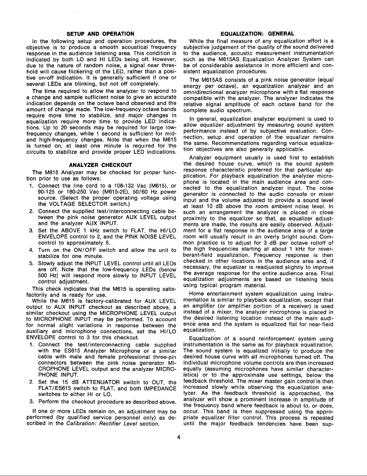
2. Install the tilt bracket assembly on the M615 Equalization Analyzer as follows: Attach the No. 6-32
machine screws and
capnuts in the two lower holes
at the front of the M615 cover. Make certain the capnuts are on the outside of the cover. Insert the ends
of the tilt bracket through the two upper holes at the
front of the M615 cover. Slip the plastic caps over
each end of the tilt bracket. Swing the tilt bracket
downward against the front panel so that the
machine screw heads provide a detent to stop the
4).
bracket from sliding (see Figure
Note that the
M615 can be replaced in its carrying case with the
tilt bracket in place and extending straight outward
from the front panel.
M615
WITH TILT BRACKET
FIGURE
3.
Model M615-2E: The Model M615-2E is supplied
4
with a detachable line cord without a three-pin male
power connector. Obtain a suitable three-pin male
plug and attach it to the line cord. The plug should
be installed by qualified service personnel. The
brown lead goes to the "hot" or "live" terminal, the
blue lead to the neutral terminal, and the
green/yellow lead to the ground or earth terminal. Select the
proper voltage range (90-125 or 180-250 Vac) using
the rear-panel VOLTAGE SELECTOR switch.
Page 4
SETUP AND OPERATION
In the following setup and operation procedures, the
objective is to produce a smooth acoustical frequency
response in the audience listening area. This condition is
indicated by both LO and HI LEDs being off. However,
due to the nature of random noise, a signal near thres-
hold will cause flickering of the LED, rather than a positive on-off indication. It is generally sufficient if one or
several LEDs are blinking, but not off completely.
The time required to allow the analyzer to respond to
a change and sample sufficient noise to give an accurate
indication depends on the octave band observed and the
amount of change made. The low-frequency octave bands
require more time to stabilize, and major changes in
equalization require more time to provide LED indications. Up to 20 seconds may be required for large
frequency changes, while 1 second is sufficient for midand high-frequency changes. Note that when the M615
is turned on, at least one minute is required for the
circuits to stabilize and provide proper LED indications.
ANALYZER CHECKOUT
M615 Analyzer may be checked for proper func-
The
tion prior to use as follows:
1. Connect the line cord to a 108-132 Vac (M615), or
90-125 or 180-250
source. (Select the proper operating voltage using
the VOLTAGE SELECTOR switch.)
2.
Connect the supplied test/interconnecting cable be-
tween the pink noise generator AUX LEVEL output
and the analyzer AUX INPUT.
3. Set the ABOVE 1 kHz switch to FLAT, the
ENVELOPE control to
control to approximately 5.
4.
Turn on the ONIOFF switch and allow the unit to
stabilize for one minute.
5. Slowly adjust the INPUT LEVEL control until all LEDs
are off. Note that the low-frequency LEDs (below
500 Hz) will respond more slowly to INPUT LEVEL
control adjustment.
This check indicates that the
factorily and is ready for use.
While the
output to AUX INPUT checkout as described above, a
similar checkout using the MICROPHONE LEVEL output
to MICROPHONE INPUT may be performed. To account
for normal slight variations in response between the
auxiliary and microphone connections, set the
ENVELOPE control to 3 for this checkout.
1.
Connect the testlinterconnecting cable supplied
with the
cable with male and female professional three-pin
connectors between the pink noise generator MICROPHONE LEVEL output and the analyzer MICRO-
PHONE INPUT.
2. Set the 15 dB ATTENUATOR switch to OUT, the
FLAT/ES615 switch to FLAT, and both IMPEDANCE
switches to either HI or LO.
3. Perform the checkout procedure as described above.
If one or more LEDs remain on, an adjustment may be
performed (by qualified service personnel only) as described in the Calibration: Rectifier
M615 is factory-calibrated for AUX LEVEL
ES615 Analyzer Microphone or a similar
Vac (M615-2E), 50160 Hz power
2,
and the PINK NOISE LEVEL
M615 is operating satis-
Level
section.
low-
HIILO
HIILO
EQUALIZATION: GENERAL
While the final measure of any equalization effort is a
subjective judgement of the quality of the sound delivered
to the audience, acoustic measurement instrumentation
such as the
be of considerable assistance in more efficient and consistent equalization procedures.
The
energy per octave), an equalization analyzer and an
omnidirectional analyzer microphone with a flat response
compatible with the analyzer. The analyzer indicates the
relative signal amplitude of each octave band for the
complete audio spectrum.
In general, equalization analyzer equipment is used to
allow equalizer adjustment by measuring sound system
performance instead of by subjective evaluation. Connection, setup and operation of the equalizer remains
the same. Recommendations regarding various equalization objectives are also generally applicable.
Analyzer equipment usually is used first to establish
the desired house curve, which is the sound system
response characteristic preferred for that particular application. For playback equalization the analyzer microphone is located in the main audience area and connected to the equalization analyzer input. The noise
generator is connected to the audio console or mixer
input and the volume adjusted to provide a sound level
at least
such an arrangement the analyzer is placed in close
proximity to the equalizer so that, as equalizer adjustments are made, the results are easily observed. Adjustment for a flat response in the audience area of a large
room will usually result in an overly bright sound. Common practice is to adjust for 3 dB per octave
the high frequencies starting at about 1 kHz for reverberant-field equalization. Frequency response is then
checked in other locations in the audience area and, if
necessary, the equalizer is readjusted slightly to improve
the average response for the entire audience area. Final
equalization adjustments are based on listening tests
using typical program material.
Home entertainment system equalization using
mentatioy is similar to playback equalization, except that
amHifier (or amplifier portion of a receiver) is used
an
insteyl of a mixer, the analyzer microphone is placed in
,desired listening location instead of the main audi-
the
ewe area and the system is equalized flat for near-field
eqdalization.
Equatization of a sound reinforcement system using
instrumentation is the same as for playback equalization.
The sound system is equalized
desired house curve with all microphones turned off. The
individual microphone volume controls are then increased
equally (assuming microphones have similar character-
istics) or to the approximate use settings, below the
feedback threshold. The mixer master gain control is then
increased slowly while observing the equalization analyzer. As the feedback threshold is approached, the
analyzer will show
the frequency band where feedback is about to, or does,
occur. This band is then suppressed
priate equalizer filter control. This process is repeated
until the major feedback tendencies have been
M615AS Equalization Analyzer System can
M615AS consists of a pink noise generator (equal
10 dB above the room ambient noise level. In
rolloff of
instru-
initially to produce the
a
prominent increase in amplitude of
using the appro-
sup-
Page 5
pressed and a reasonable sound volume level can be
produced. A talk or other performance test of each open
microphone is then conducted and the quality of the
sound produced is sampled by listening in various locations throughout the audience area. Additional equalization adjustments are made based on the listening
evaluation, while taking care to avoid any significant reduction in the feedback threshold previously achieved.
Equalization of a stage monitor system using analyzer
equipment is similar to playback or house system equalization except that measurements and evaluation are
confined to the performer's stage area. The pink noise
generator is connected to the mixer input and the audio
console or mixer volume adjusted to provide an output
from the monitor speakers at least 10 dB above the ambient noise level. A person is placed in front of the lead
performer's microphone (to simulate performance conditions) and the analyzer microphone is placed next to the
person at ear level to sample the sound field in that
area. The analyzer microphone output is viewed on the
equalization analyzer and initial response adjustments,
such as low-frequency
sole or mixer volume control for the performer's microphone is then set to a stable point slightly below the
feedback threshold. The monitor master gain control is
gradually increased until an obvious increase in amplitude in a particular frequency band is noted on the
equalization analyzer. This is the onset of feedback and
the appropriate equalizer filter control is used to reduce
the system response in this area. This process is continued until satisfactory gain before feedback and the
desired response is achieved.
former microphone position is made to determine if an
adequate feedback threshold is attainable. Final adjustment of the equalizer and/or individual channel tone
controls (if available) is made to improve quality or intelligibility of the sound presented to the performers.
rolloff, are made. The audio con-
A
voice test of each per-
OPERATION
This section contains basic instructions for connecting
and operating the
It should be noted that individual room acoustics, equipment characteristics, and increasing operator proficiency
will all contribute to the development of equalization
analysis techniques which may differ somewhat from the
guidelines described here.
M615AS Equalization Analyzer System.
Connections
Interconnect the units of the sound system as for normal operation. Connect the M615 pink noise generator
output to the input of the console,
(either microphone, or aux level using the supplied test/
interconnecting cable), amplifier or receiver, and, if the
M615 microphone-level output is used, set the MICROPHONE IMPEDANCE switch as required. Connect the
ES615 Analyzer Microphone to the M615 microphone input. Set the
phone input IMPEDANCE switch to LO. If a flat-response
equalization microphone rather than the
used, set the
PEDANCE switch as required.
FLAT/ES615 switch to ES615 and the micro-
FLAT/ES615 switch to FLAT and the IM-
mi~er, preamplifier
ES615 is to be
Sound Reinforcement Systems
1. Place the speakers of the sound reinforcement sys-
tem in listening area locations to provide optimum
audience coverage. Maximum coverage in many installations is obtained with the speakers on each
side of the sound source and as far forward as possible. Assuming a single speaker to either side of
the sound source, the speakers should be positioned
so that an imaginary line from the center of each
speaker runs to the back row of the audience area.
For "clustered" speaker installations covering a
wide area, each speaker should be positioned so
that its angle of coverage slightly overlaps that of
the speaker next to it as their sound output enters
the audience area. The pink noise generator output
of the M615 may be used (at low system power
levels) to provide an audible signal source for
speaker placement checkout. A listening test of the
audience area may be made for dead zones, frequency response variations, or other symptoms of
improper coverage. Avoid listening to speaker pattern overlap areas, as these are apt to be erratic.
2.
Set the front-panel ABOVE 1 kHz switch as required.
A system equalized using the
provides a smooth
1 kHz, which usually results in the most pleasing
audience reaction. Research has shown that a per-
fectly flat frequency response curve generally yields
an overly bright sound that is made more natural by
using this gradual high-frequency
position is normally used only for near-field equal-
ization particularly in small or acoustically "dead"
rooms, or for electrical equalization of preamplifiers,
tape recorders, and amplifiers.
3.
Set the 15
LO ENVELOPE control to 12, and the PlNK NOISE
LEVEL control to
ization microphone on a microphone stand at a
seated listening height, approximately on-axis to one
of the speakers and mid-way between the speaker
and the rear of the audience area. Turn on all units
in the system and allow one minute
Starting at
up until the first LO LED goes out or flickers. Note
the INPUT LEVEL control setting and reduce it by
approximately
ity is low enough to prevent the ambient noise level
from affecting equalization results. If the MIC input
is being used and the initial INPUT LEVEL control
setting is
should be set to IN and the process repeated. If the
INPUT OVERLOAD LED comes on during adjust-
ment of the INPUT LEVEL control, the control setting
is too high and must be reduced for proper LO LED
indications. IMPORTANT: The equalization procedure requires a stable ambient noise level. Extraneous
noise such as construction, rehearsal, or loud conversation will interfere with measurements and
adjustments.
4.
Slowly increase the PlNK NOISE LEVEL control until
one to three HI LEDs go on. Most LO LEDs will go
out; those remaining on at either end of the spectrum
indicate the bandwidth limits of the sound reinforce-
ment system. It is important to note that any attempts
to equalize at these bandwidth limits must be done
judiciously. Excessive boosting of these frequencies
dB
0, turn the INPUT LEVEL control slowly
4
or less, the
3
dB per octave rolloff starting at
ATTENUATOR switch to OUT, the
0. Place the ES615 or other equal-
3.
This assures that the input sensitiv-
15
ROLLOFF position
rolloff. The FLAT
warmup time.
dB ATTENUATOR switch
HI/
Page 6

can cause power amplifier overloading and possible readjustment of speaker positions, or physical
speaker damage. Figure 5 shows a typical room changes such as the addition or removal of
response prior to equalization, with initial peaks absorbing material. It is important to note that major
occurring around
adjustments for this condition would be a reduction main listening area should not be made.
of the 125 and
these HI LEDs off. (For clarity, the high-frequency
rolloff is not depicted.)
TYPICAL ROOM RESPONSE
BEFORE EQUALIZATION
5.
Observe which HI LEDs have turned on and slowly
adjust the corresponding equalizer frequency filter
control in the "cut" direction until those LEDs just
turn off. Do not adjust the equalization control any
more than necessary to turn the LED off. Note that
in the process of reducing an equalizer control to
turn a HI LED off, the LO LEDs of one or both adjacent octave bands may turn on as a result of
normal filter interaction. Simply slightly readjust the
equalizer controls of the affected octave bands until
the LO LEDs again go out.
6. When both HI and LO LEDs are off, slowly reduce
the
HI/LO ENVELOPE control. Some HI LEDs will
begin to turn on, indicating relative peaks in response. Repeat step
Figure 6 shows the room response of Figure 5 after
initial equalization of the low frequencies. Note that
as the
the 500,
velope and these HI LEDs have turned on. Equalizer
adjustments would now be made to turn these LEDs
off.
Continue reducing the
eliminating peaks that appear. When a satisfactory
envelope has been obtained, move the equalization
microphone to other positions in the listening area
and note which HI or LO LEDs turn on. It may be
necessary to readjust the INPUT LEVEL control for
a minimum number of lit LEDs due to level differences between locations. The
control setting may be increased to determine the
extent of response changes at the new location. At
this point, corrective action may be taken by either
slight adjustment of the equalizer frequency filters,
HIILO ENVELOPE control has been reduced,
1K and
125.
and 250 Hz. Initial equalizer changes to the equalizer settings obtained in the
250
Hz filter control settings to turn
FIGURE
4K
5
5
to eliminate these peaks.
peaks are now outside the en-
HI/LO ENVELOPE control and
HI/LO ENVELOPE
TYPICAL ROOM RESPONSE AFTER
LOW-FREQUENCY EQUALIZATION
FIGURE 6
7.
The sound system has now been equalized to provide a smooth, controlled-rolloff frequency response,
free of major irregularities. Figure
room response after equalization, with the
ENVELOPE control at 2 (&I) dB. Note that no attempt has been made to "boost" the frequencies
beyond the bandwidth limits of the system.
At this point, feed the system with program-type
material (live or recorded) and make slight adjust-
ments to brighten or otherwise modify equalized
response using the system's tone controls.
TYPICAL ROOM RESPONSE
AFTER EQUALIZATION
FIGURE
Stage
former with an intelligible source of the sound required
for the performance.
Monitor
Equalization of stage monitor systems is performed
principally to eliminate feedback while providing the per-
1.
Connect the performer's microphone to the sound
system and adjust the levels to a point just below
feedback. Place the
crophone at the performer's ear level (facing forward
Systems
7
ES615 or other equalization mi-
7
shows the final
sound-
HI/LO
Page 7

toward the monitor speaker), and connect the ES615
to the M615. Make certain someone is standing in
the performer's position to simulate performance
conditions.
2. It is advisable to roll off the low-frequency response
of the system by reducing the settings of the equalizer frequency controls below 250 Hz. Attenuation of
frequencies in this range reduces low-frequency
noise pickup without affecting intelligibility.
Set the ABOVE 1 kHz switch to FLAT. This position
3.
is used for near-field conditions such as are en-
countered in stage monitor setups.
4.
Set the 15 dB ATTENUATOR switch to OUT, and HI/
LO ENVELOPE control to 12, and the PlNK NOISE
LEVEL control to
and allow one minute
turn the INPUT LEVEL control slowly up until the
first LO LED goes out or flickers. Note the INPUT
LEVEL control setting and reduce it by approximate-
3.
This assures that the input sensitivity is low
ly
enough to prevent the ambient noise level from affecting equalization results. If the MIC input is being
used and the initial INPUT LEVEL control setting is
4
or less, the 15 dB ATTENUATOR switch should be
set to IN and the process repeated. If the INPUT
OVERLOAD LED comes on during adjustment of the
INPUT LEVEL control, the control setting is too high
and must be reduced for proper LO LED indications.
IMPORTANT: The equalization procedure requires a
stable ambient noise level. Extraneous noise such as
construction, rehearsal or loud conversation will in-
terfere with measurements and adjustments.
5. Slowly increase the PlNK NOISE LEVEL control until
one to three HI LEDs go on. Most LO LEDs will go
out; those remaining on at either end of the spec-
trum indicate the bandwidth limits of the monitor
system. It is important to note that any attempts to
equalize at these bandwidth limits must be done
judiciously. Excessive boosting of these frequencies
can reduce intelligibility, and cause power amplifier
overloading and possible speaker damage.
6. Observe which LEDs have turned on and slowly adjust the corresponding equalizer frequency filter
control in the "cut" direction until those LEDs just
turn off. Do not adjust the equalization control any
more than necessary to turn the LED off. Note that
the process of reducing an equalizer control to
in
HI
turn a
jacent octave bands may turn on as a result of
normal filter interaction. Simply slightly readjust the
equalizer controls of the affected octave bands until
the LO LEDs again go out.
7.
When both HI and LO LEDs are off, slowly reduce
the
begin to turn on, indicating relative peaks in response. Repeat step 6 to eliminate these peaks.
Continue reducing the
eliminating peaks that appear. When a satisfactory
envelope has been obtained, set the audio console
or mixer volume control for the performer's micro-
phone to a stable point slightly below the feedback
threshold. Gradually increase the monitor master
LED off, the LO LEDs of one or both ad-
HI/LO ENVELOPE control. Some HI LEDs will
0. Turn on all units in the system
warmup time. Starting at 0,
HI/LO ENVELOPE control and
gain control until an obvious increase in amplitude
in a particular frequency band is noted on the
This is the onset of feedback; adjust the appropriate
equalizer filter control to reduce the system response
in this area. Continue this process until satisfactory
gain before feedback and the desired response is
achieved. Make a voice test of each performer microphone position to determine if an adequate feedback threshold is attainable. Final adjustment of the
equalizer and/or individual channel tone controls
(if available) may then be made to improve quality
or intelligibility of the sound presented to the performers.
Home Entertainment Systems
Home entertainment (hi-fi) systems incorporating an
equalizer may be properly equalized using the M615 as
follows.
1. Set all controls on the hi-fi system to flat. Set the
volume control to maximum or, if a loudness com-
pensation switch is provided, turn the loudness
switch off. Place the
sired listening area, at approximately listening height
and facing the normal listening direction (front center).
2. Set the ABOVE 1 kHz switch as required. Although
the FLAT position is applicable to most home enter-
tainment system (near-field) setups, in large or "live"
rooms a far- or reverberant-field condition may
sometimes be encountered in which the
position could be used. This position provides a
3
smooth
to be most pleasing to audiences in larger listening
areas.
3.
Connect the pink noise generator output to the re-
ceiver or amplifier auxiliary input of one channel.
4.
Set the 15 dB ATTENUATOR switch to OUT, the
HI/LO ENVELOPE control to 12, and the PlNK NOISE
LEVEL control to
and allow one minute
turn the INPUT LEVEL control slowly up until the
first LO LED goes out or flickers. Note the INPUT
LEVEL control setting and reduce it by approximately
enough to prevent the ambient noise level from af-
fecting equalization results. With the MIC input in
use, if the initial INPUT LEVEL control setting is
4
or less, the 15 dB ATTENUATOR switch should be
set to IN and the process repeated. If the INPUT
OVERLOAD LED comes on during adjustment of the
INPUT LEVEL control, the control setting is too high
and must be reduced for proper LED indications.
IMPORTANT: The equalization procedure requires
a stable ambient noise level. Extraneous noise such
as TV, air conditioners, or loud conversation will interfere with measurements and adjustments.
5. Slowly increase the PlNK NOISE LEVEL control until
one to three HI LEDs go on. Most LO LEDs will go
out; those remaining on at either end of the spec-
trum indicate the bandwidth limits of the system. It
is important to note that any attempts to equalize at
these bandwidth limits must be done judiciously. Ex-
cessive boosting of these frequencies can cause
amplifier overloading and possible speaker damage.
dB per octave rolloff which has been found
3.
This assures that the input sensitivity is low
ES615 microphone in the de-
0. Turn on all units in the system
warmup time. Starting at
M615.
ROLLOFF
0,
Page 8

CAUTION:
Excessively high signal levels for long
periods of time may damage many hi-fi speakers.
Equalization analysis should be performed at as low
a signal level as possible.
observe which HI LEDs have turned on and slowly
adjust the corresponding equalizer frequency filter
control in the "cut" direction until those LEDs just
turn off. Do not adjust the equalization control any
more than necessary to turn the LED off. Note that in
the process of reducing an equalizer control to
turn a HI LED off, the LO LEDs of one or both adjacent octave bands may turn on as a result of normal filter interaction. Simply slightly readjust the
eaualizer controls of the affected octave bands until
thk LO LEDs again go out.
7.
When both HI and LO LEDs are off, slowly reduce
HI/LO ENVELOPE control. Some HI LEDs will
the
begin to turn on, indicating relative peaks in response. Repeat step 6 to eliminate these peaks.
Continue reducing the
HIILO ENVELOPE control
and eliminating peaks that appear until a satisfactory envelope has been obtained.
8. Connect the pink noise generator output to the receiver or amplifier auxiliary input of the other channel
and repeat steps
9.
Once equalization of the hi-fi system has been
4
through 7 for the other channel.
achieved, the system equalization or tone controls
can be adjusted slightly to satisfy personal preference.
SERVICING
WARNING
Voltages in this equipment are hazardous to life.
Refer servicing to qualified service personnel.
Disassembly
Disconnect ac power. The M615 cover may be removed
by removing one screw at the top center of the front and
rear panels and one screw at each side of the chassis
bottom.
Printed circuit assembly
connecting connectors J7 and J8 from the board (see
Parts Placement diagram), and removing the board from
the nylon fasteners by squeezing the upper protruding
tabs on the circuit board side inward and sliding the
baard outward and off the fasteners.
Printed circuit assembly A9 may be removed by first
removing two screws on the bottom of the chassis which
secure the metal shield associated with Assembly
Lift the shield and circuit assembly upward and out of
the chassis. Remove the circuit assembly from the shield
by squeezing the upper protruding tabs of the nylon
fasteners on the circuit board side, and sliding the board
outward and off the fasteners.
The multiple printed circuit assembly consisting of A2
through A8 may be removed by first removing four
screws on the bottom of the chassis. Carefully lift the
assembly upward and out of the chassis. As the as-
sembly becomes clear of the chassis, remove connectors
J9, J10, J11 and J901. Remove the top support bracket
and metal bracket from the LED end of the boards.
A1 may be removed by dis-
A9.
Printed circuit assemblies
A3
through
A8
may now be removed from motherboard A2 by pulling outward. Always
pull boards and connectors straight to avoid bending
male pins.
Filter/Rectifier/Comparator
When replacing one of the
Replacement
FiIter/Rectifier/Comparator
printed circuit assemblies (A3 through A7), the filter center frequency (TUNE: RX03, RX15)* and rectifier (LEVEL:
RXOI, RX16)* potentiometers must be calibrated as follows. Note that TUNE and LEVEL potentiometers for two
filter frequencies are present on each assembly. The
TUNE adjustment for each frequency must be performed
before the LEVEL adjustment.
Calibration: Filter Center Frequency
To calibrate the filter center frequency, set INPUT LEV-
EL control to
10 and apply a -40 dBV (10 mV) sinusoidal
input signal at the desired frequency to the analyzer aux
input. Connect the signal from test point TP201 to the
horizontal input of an oscilloscope. Connect the signal
from the filter test point
(TPX02) to the vertical input of
the oscilloscope. (The signals must be obtained using a
probe with a
1
k resistor in series with and as close to
the tip of the probe as possible.) Adjust the oscilloscope
to produce a circular or elliptical Lissajous pattern.
Ad-
just the TUNE potentiometer (RX03) until a straight line
denoting 0" phase shift is observed on the oscilloscope.
Repeat this procedure for the other filter frequency on
the assembly using test point
TPX03 and TUNE poten-
tiometer RX15.
Calibration: Rectifier Level
If the
Filter/Rectifier/Comparator
assembly has been
replaced, make certain the TUNE potentiometers have
been adjusted prior to LEVEL potentiometer adjustment.
If, during the Analyzer Checkout procedure, one or more
LEDs remain on, the LEVEL potentiometer for that frequency may be readjusted slightly as follows.
To calibrate the rectifier level, set the ABOVE 1 kHz
switch to the FLAT position and apply the AUX LEVEL
output of the pink noise generator to the analyzer AUX
INPUT. Set the
PINK NOISE LEVEL control to 5 and carefully adjust the INPUT LEVEL control until all 10 LO LEDs
blink randomly on and off except for the frequencies requiring calibration. Adjust the LEVEL potentiometer
(RXOI
or RX16) until the associated LO LED blinks randomly.
Repeat this procedure for any other frequency requiring
adjustment.
Printed Circuit Assembly Connectors
Printed circuit assembly connectors J7 through J11,
J201 through J206, and J901 use the AMP Incorporated
Commercial Interconnect System. To replace a lead and
its associated connector contact, proceed as follows.
Using a scribe or other pointed instrument, depress the
contact through the slots at both sides of the connector
housing. This will free the contact and allow it to be re-
moved from the rear of the connector housing. Trim a
YE
new lead so that
trimmed lead in a new contact (Shure Part No.
inch of wire appears. Insert the
56A225).
Crimp the wire and the lead insulation to the contact.
Solder the wire to the crimped connection. lnsert the new
contact (with attached lead) in the connector housing,
pushing firmly to lock the contact.
*
For reference designat~ons containing "X" (RX03, TPXOP, etc.), substitute
the appropriate board number (3 through
7)
for the board being adjusted.
Page 9

MODEL M615 REPLACEMENT PARTS LIST
Reference
Designation
Replacement
No.
Kit
*
Replacement Kit Consists
aty-.
I
Printed Circuit
Assembly, Preamplifier
Printed Circuit
Assembly, Overload Detector
and Mother Board
Printed Circuit
Assembly, 32
Printed Circuit
Assembly, 125
Printed Circuit
Assembly, 500
Printed Circuit
Assembly,
Printed Circuit
Assembly,
Printed Circuit
Assembly, Noise Generator
Printed Circuit
Assembly, Power Supply
Diode, Silicon, Computer,
75v
Description
2
8
&
63
&
&
&
4
&
16 kHz
Of:
Hz
250
1,000
kHz
1
1
I
Hz
Hz
I
Commercial
Alternate
None
None
None
None
None
None
None
None
None
56A225
Diode, Light-Emitting
Silicon Rectifier,
V2
A
Zener Diode,
Fuse,
Slo-Blo %A, 250V
(M615-2E only)
Connector, Female 3-Pin
Audio
Connector, Phono Jack,
Grounded Shell
Connector, Phone Jack,
Shorting
Connector, Male, 3-Pin
Audio
Connector, Phone Jack,
Shorting
Connector, Phono Jack,
Grounded Shell
1
Connector Contact (only)
100V,
SilLcon, 27V
1
Monsanto MV5075C
I
Motorola 1 N4002
Motorola 1 N4750A
Littelfuse
31 5.125
Switchcraft
D3F
Switchcraft
351 2A
Switchcraft
11
2A
Switchcraft
D3M
Switchcraft
11 1
Switchcraft
3511A
None
Ac
95A689
90A1715A
*
Parts listed as RKC Kits should be ordered by that kit number. Any orders received for piece parts where RKC Kit number
shown will be shipped in
RKC
quantities.
Receptacle
Knob, INPUT LEVEL
9
(M615-2E
only)
None
None
is
Page 10

MODEL M615 REPLACEMENT PARTS
LIST
(Continued)
Reference
Designation
M
P2
M P3
P Ll
Q101, Q103,
Q105, (2802803, Q805-807
Q102, Q104,
Q106, Q801,
Q804, Q808
Q107
Q108
Q809
(2901
R4/ R6
R5
R301, R316,
R401, R416,
R501, R516,
R601, R616,
R701, R716
R303, R315,
R403, R415,
R503, R515,
R603, R615,
R703, R715
S1-5
S6
S6
S7
TI-2
T3
T3
U201, U302
U301
W1
W1
Replacement
Kit No.
*
-
-
RKC45
R KC89
RKC65
RKC66
-
-
-
-
-
-
-
-
-
-
-
-
-
-
-
-
Qty.
-
-
1
4
-
1
1
-
-
-
-
-
-
-
-
-
-
-
-
-
-
-
-
Part No.
65B931A
90E1662
80A79
86A350
86A348
86A334
86A335
86A373
86A374
46A064
46A065
46A062
468062
55B83
5591 03
55A126
55A116
90F2150
51A269
51 A274
86A806
86A805
95A632
90A1888
Replacement
Knob, PINK NOISE LEVEL
Knob,
Lamp, Indicator, Neon
Transistor, Silicon, NPN
Transistor, Silicon, PNP
Transistor, Silicon, NPN
Transistor, Silicon, PNP
Transistor, Field
Effect, N-Channel
Transistor, Silicon, NPN
Potentiometer, Dual,
Audio Taper,
Potentiometer, Modified
Log Taper, 5k
Trimmer Potentiometer,
2.5k
Trimmer Potentiometer,
30k
Switch, Slide, DPDT
Switch, Slide, DPDT
(M615)
Switch, Slide, DPDT
(M615-2E)
Switch, Slide, DPDT
(M615-2E only)
Transformer
Assembly
Transformer, Power
Transformer, Power
(M615-2E)
Integrated Circuit, Quad
Comparator
Integrated Circuit, Quad
Operational Amplifier
Cable and Plug Assembly, Ac
(M615)
Cable and Plug Assembly, Ac
(M615-2E)
Kit Consists
Description
HI/LO ENVELOPE
Of:
50k/50k
&
Shield
(M615)
Commercial
Alternate
None
None
Leecraft
36N1311-6
Motorola
2N5210
Motorola
2N5087
TI TIS92
TI TIS93
Siliconix or
lntersil E230
Motorola
2N4922
None
None
V101 S252B
CTS
CTS V1 OlS253B
Switchcraft
46206LR
Switchcraft
46206LR
Marquardt
4021.01 01
Marquardt
4021.0201
None
None
None
Raytheon
LM339DB, RCA
CA339G, TI
SN72339N
Raytheon
RC3403ADB
None
None
*
Parts listed as RKC
shown will be
shipped in RKC quantities.
Kits should be
ordered
by
that
k~t
number.
Any orders received
10
for
piece parts
where RKC Kit number
is
Page 11

Page 12

PRINTED CIRCUIT ASSEMBLY
A1
2430-1
1629-1
PRINTED CIRCUIT ASSEMBLY A2
Page 13

PRINTED CIRCUIT ASSEMBLIES A3-A7
2432-1 /631-2
NOTCH
NOTCH
PRINTED CIRCUIT ASSEMBLY A8
2667-4/812-2
Page 14

PRINTED CIRCUIT ASSEMBLY A9
FURNISHED ACCESSORIES
Tilt Bracket 47A100
Carrying Case .65A1130B
Test/lnterconnecting Cable .95A844
M615 parts readily available through local electronics
parts distributors are not shown on the accompanying
parts list. Values are shown on the circuit diagram. Commercial parts not readily available and unique parts are
shown on the parts list and may be ordered directly from
the factory. The commercial alternates shown on the
parts list are not necessarily equivalent, but may be used
in the event that direct factory replacements are not im-
mediately available. To maintain the highest possible per-
formance and reliability, Shure factory replacement parts
should be used.
In addition to the parts list and circuit diagram, a parts
placement diagram and printed wiring assembly layouts
are provided to assist in parts location and identification.
This Shure product is guaranteed in normal use to be
free from electrical and mechanical defects for a period
of one year from date of purchase. Please retain proof
of purchase date. This guarantee includes all parts and
labor. This guarantee is in lieu of any and all other guar-
antees or warranties, express or implied, and there
shall be no recovery for any consequential or incidental
damages.
Carefully repack the unit and return it prepaid to:
If outside the United States, return the unit to your dealer
or Authorized Shure Service Center for repair. The unit
will be returned to you prepaid.
.................................
...........................
..................
REPLACEMENT PARTS
GUARANTEE
SHIPPING INSTRUCTIONS
Shure Brothers Incorporated
Attention: Service Department
1501 West Shure Drive
Arlington Heights, Illinois 60004
Page 15

PRINTED
PREAMPLlFl
CIRCUIT
ER
r--
ASSEMBLY
BOARD
--
A1
--7
I
OVER
CIRCUIT
LORD
DETECTOR
ASSEMBLYAZ
AND
MOTHER
BObRD
I
(PRINTEDNRcuIT
I
I
FILTER, RECTIFIER
I
i
ASSEMBLIE~A~-A~
AND
COMPARATOR
TYP.
(PRINTED
BOARDS
CIRCUIT
ASSEMBLY
A3
SHOWN)
--1
ALL CAPACITORS EXCEPT CXOI
*REFERENCE
ARE
AND
NOTES:
I. ALL ClPAClTORS IN
2.
3.
DESIGNATIONS
SHOWN
FOR
r
;HRzi;
ASSEMBLY
X"
VOLTS.
REPLACE
OTHERWldE SHOWN. ELECTROLYTIC CAPACITORS SHOWN
IN
,AF
ALL RESISTORS 1/4W, 10%
SHOWN.
THE FOLLOWING SVMBOLS DENOTES
d-7
WITH
#
CX07
AND ALL RESISTORS
FOR
RESISTORS
A3.
FOR
PC
ASSEMBLY
pF
AND 50V OR MORE UNLES5
P.C.
GROUND
OTHER
UNLESS
BOARD
AND
NO.
OTHERWISE
(3-7).
CAPACITOR5
ASSEMBLIES
IN
TABLE
WITH
A4-A7,
r)RE
57.
ASTERISKS
SEE
TABLE
MODEL
M615
CIRCUIT DIAGRAM
Page 16

I
PRINTED
I
PINK
I
CIRCUIT
NOISE
-
GLNERATOR
r4SSEMBLY
-
-
A6
BOARD
-
- -
-
--
-
-
-
-
--
1
I
I
120
50160
5
VAC
HER
WATTS
72
PRINTED CIRCUIT
POWER
SUPPLY
r--
ASSEMBLY
BOARD
A9
--7
I
I
(MIINSI
POWER
YO-BLD
POWER
BLU
BU(/RED
M615-2E
POWER
SUPPLY
MODEL M615 CIRCUIT DIAGRAM
 Loading...