

Page 1
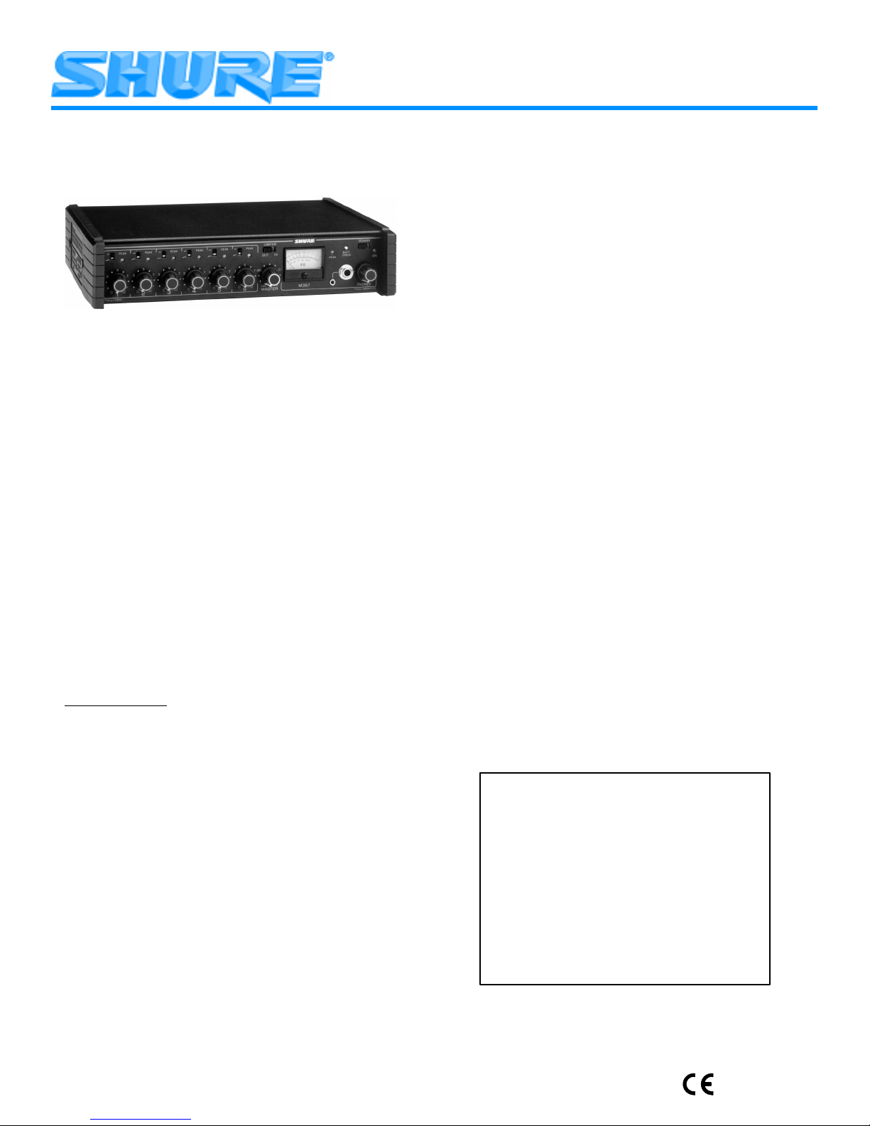
MODEL M367 AND M367E MICROPHONE MIXERS
The Shure Model M367 is a six-input, portable microphone
mixer/remote amplifier specifically designed for professional applications in electronic news gathering (ENG), electronic field
production (EFP) and general audio mixing. It sets a new standard for portable mixer performance and features. Exceptionally
low–noise design makes the M367 ideal for use with digital transmission links and digital video/audio recording media, including
ISDN and DAT. Compact and rugged, the M367 is built to withstand the most demanding field production conditions. In addition, its excellent performance, versatility and features make it an
ideal choice for studio, remote, or sound reinforcement use, and
as an add-on mixer for expanding existing facilities.
Each M367 handles up to six microphones or line-level signals. Any high-quality, low-impedance, balanced microphone
using a dynamic or condenser* transducer (including wireless
and shotgun types) can be used. Additional M367 or other Shure
mixers can be linked using the rear–panel mix bus jacks.
The M367 is supplied with rubber feet, detachable power cord,
and spare power line fuse. Model A367R is an optional rack
mount kit enabling the M367 to be mounted in a standard 483
mm (19–inch) audio equipment rack (two rack units).
The M367 is supplied for operation at 100–120 Vac, 50/60 Hz,
and the M367E for operation at 220–240 Vac, 50/60 Hz. Each
model is internally switchable to the other’s operating voltage
range.
*Self-powered or operable on 12 or 48 Vdc phantom power.
Features
Exceptionally quiet design, suitable for use with DAT, record-
able CD, and other digital formats
Extended frequency response of 20 Hz to 20 kHz
Dynamic range greater than 100 dB
Transformer–balanced inputs and outputs for superior rejec-
tion of RFI and electromagnetic hum
Six selectable mic/line inputs
Selectable mic/line output and dedicated line output
Metal XLR input and output connectors
Wide–range input gain controls handle hot signal levels with-
out attenuators
48 V or 12 V phantom power for condenser microphones
Switchable low-cut filters on each input
Peak indicator LED on each input
Model M367 AND M367E User Guide
Professional mechanical VU meter—LED backlighting for
high reliability , no lamp replacement
Bi–color output LED shows output limiting and peak indication
Output peak limiter with switchable threshold
1 kHz tone oscillator
Mix bus jack to link M367s or other mixers
Balanced Mix Bus connection to other M367s
Monitor input via Phones push/pull control
Headphones volume control
1/4” and 3.5 mm jacks for stereo headphones
Customized operation via internal DIP switches, trim pots, and
optional alternate wiring
Regulated voltage rails (±15 Vdc) provide exceptional head-
room
Power-on LED
Battery check switch and low battery warning indication
AC power operating range from 100 to 120 volts, 50/60 Hz or
220–240 Vac, 50/60 Hz
Soft-touch, color-coded control knobs with raised position indi-
cators
Rugged all metal chassis with protective end caps
Detachable ac power cord
Backup/field operation powering with two 9–volt batteries
Automatically and silently switches to battery operation should
ac voltage fail
Designed and manufactured in U.S.A. with legendary Shure
reliability and performance
IF YOU’VE USED THE M267...
Your new M367 mixer contains numerous features and improvements not found in the M267 model. If you don’t have the
time or inclination to read this informative data sheet, these features are identified in the box below . You will then be familiar with
the most important new capabilities of your M367.
•
12–, 48–volt phantom power
•
Input clipping LEDs
•
Detachable power cord
•
Two XLR outputs
•
Side battery compartment
•
Power–on LED
•
Headphones monitor circuit
•
Output peak/limiter LED
•
Selectable mix bus, balanced for M367s
•
Adjustable limiter threshold
•
Meter LED backlighting
•
VU lamp mode selector
•
Monitor input sensitivity selector
•
Program/monitor input selector
2000, Shure Incorporated
27A8511 (TG)
1
Printed in U.S.A.
Page 2
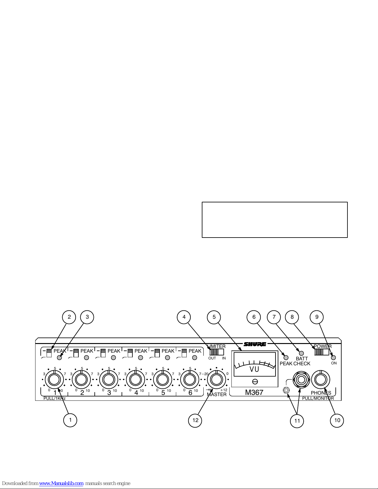
FRONT PANEL CONTROLS AND INDICATORS (Figure 1)
Á
Á
Á
1. Input Gain Control: Adjusts the gain level of each input chan-
nel. Rotating the knob counterclockwise reduces gain
and
raises the input clipping point. Use a low control setting to handle “hotter” input signals without distortion. With the new M367
input circuit, microphones with a “hot” output can be used without an in-line pad (attenuator).
For best performance, adjust each Input Gain Control so the
associated Input Peak LED illuminates red only on the loudest
signal peaks.
1 kHz Tone Oscillator (Channel 1): Activated by pulling out
Input Channel 1 Gain knob.
Note:
Tone level is adjusted using the Input 1 control
and
the
Master control. Use this tone to send a reference signal level
to any device connected to an M367 output.
2. Input Low-Cut Filter Switch: Provides low–frequency rolloff
to reduce wind noise and rumble. When using the filter, the frequency response is down 7 dB at 150 Hz. Rolloff slope is 6 dB
per octave.
3. Input Peak LED: Illuminates red if input signal reaches 6 dB
below clipping (distortion).
4. Limiter Switch: Activates a fast–acting, peak–responding
limiter. The limiter helps prevent overload distortion from unexpected loud input signals. Limiter action is indicated by the
Output Peak/Limiter LED, which will illuminate green. The
0.1-second release time is optimized for speech signals; an internal modification can provide a 1-second release time for
music signals (see
Internal Modifiable Functions
).
5. Output Level Meter: The illuminated mechanical VU meter
provides reliable operation and excellent visibility in all environmental and ambient lighting conditions.The meter response approximates true VU characteristics (about 300 ms
rise and fall, 1% to 5 % overshoot). If a slower response is desired, see
Internal Modifiable Functions
. 0 VU is switchable
between +4 and +8 dBm output level by an externally accessible switch (see
Internal Switches and Controls
).
An LED array illuminates the meter, eliminating lamp replacement. The meter is illuminated at all times when the mixer is
ac–powered. With dc power, the meter illumination is activated
by the Batt Check switch.
6. Output Peak/Limiter Bi–Color LED: Illuminates red when
output signal reaches a factory preset peak level of +12 dBm
(6 dB below clipping). If the limiter is switched on, the LED illuminates green to indicate limiter operating threshold has been
reached. The LED will still illuminate red if the preset peak level
is reached before the limiter activation point is reached.
7. Battery Check Switch: When pressed, the status of the two
9V batteries is indicated on the VU meter: an indication in the
red portion of the scale indicates adequate battery power.
When the meter reads 0 VU, the batteries are at about 13.5
volts. A low battery condition is also indicated when the Power–On LED flashes.
When using ac power (no batteries in
compartment), the battery check gives no indication.
When the M367 is battery–powered and the switch is pressed
momentarily, the meter illumination turns on for about 10 seconds. Changing meter illumination action to toggled (meter illumination stays on until the switch is pressed again) can be
accomplished via internal DIP switch 6 (see
and Controls
Note:
for instructions).
The audio signal is not interrupted when the Battery
Internal Switches
Check switch is pressed.
8. Power–On/Off Switch: Turns the mixer on and off.
9. Power–On LED: Illuminates green to indicate power is on.
Flashes to indicate low batteries, typically when about 30 minutes of operation remains.
10. Headphones Gain Control: Rotates to adjust headphones
volume level.
WARNING
The headphones circuit is capable of producing
high volume levels that can damage the user’s
hearing. Make sure headphone volume setting
is low (full CCW) before putting headphones on.
Pull/Monitor Switch: When knob is pulled outward, audio signal from Monitor In jack is sent to headphones output, interrupting the program signal to the headphones. If an attenuated
program signal with the monitor signal is desired, refer to the
Internal Switches and Controls
section.
11. Headphones Outputs: Stereo 1/4–inch phone jack and stereo 3.5 mm miniature phone jack may be used separately, simultaneously , or as auxiliary feeds to other equipment.
12. Master Gain Control: Sets mixer output gain. Set to 0 dB
position for unity gain output stage.
2 3 4
PEAK
5
3
0
10
PULL/1KHz
PEAK
5
7
3
0
10
21
PEAK
5
0
7
10
7
3
1
5
PEAK
5
3
0
10
PEAK
5
7
3
7
3
0
543
0
10
PEAK
5
10
6
7
-20
-
LIMITER
OUT IN
0
+12
MASTER
12
FRONT PANEL CONTROLS AND INDICATORS
FIGURE 1
2
6 7 8 9
BATT
CHECK
PEAK
VU
M367
11
POWER
ON
PHONES
PULL/MONITOR
10
Page 3

1 2 3 4
100/120 VAC 50/60 Hz 100 mA
SPARE
LINE
MIC
OUTPUT
LINE PHANTOM
OFF ON
MONITOR
IN
MIC
LINE
6
MIC
5
LINE
LINE
MIC
4321
INPUT
MIC
LINE
MIC
LINE
9 8 7 6 5
REAR PANEL CONNECTORS AND CONTROLS
FIGURE 2
REAR PANEL CONNECTORS AND CONTROLS (Figure 2)
1. Mic/Line Level Output Switch: Selects Mic or Line level to
BALANCED
match proper input level of the device connected to the M367
output. Mic signal level is typically 0.0001 – 0.003 V; Line signal level is typically 0.1 – 3.0 V.
2. Phantom Power Switch: Activates 12–volt phantom power
TO M367 #1 TO M367 #2
UNBALANCED
on each input set to Mic Level input. If needed, 48–volt phantom power is available through activation of internal DIP switch
No. 7 (see
Note:
phantom power.
3. Mic/Line Level Input Switches 1–6: Selects Mic or Line to
match the incoming signal level. Mic signal level is typically
0.0001 to 0 .003 volts and Line signal level is typically 0.1 to
3.0 volts. In the Line level position, phantom power is disconnected from the inputs.
4. M267/M367 Mix Bus Level Switch: Selects a matching mix
bus level for the mixer connected to the M367. The M267 position is used when a Shure M267 (or Shure FP42, FP51, M67
or SE30) is connected; the M367 position is used when another M367 (or Shure FP32A) is connected to the Mix Bus.
In the M267 position, mixer output noise may in-
crease up to 30 dB, depending on the Master out-
put control setting. Unless required for mix bus hook-
up with an M267 or similar mixer,
5. Mix Bus Jack: Allows two mixers to be connected together.
The Mix Bus connection is “two–way” and pre–Master. When
two M367 mixers are connected via the Mix Bus, all 12 inputs
appear at both mixers’ outputs. The Master Gain control of either M367 can be adjusted without affecting the other mixer’s
output. This provides the equivalent of a 12–input mixer with
two separate Master output sections.
NOTE:
when they are connected via the Mix Bus. Increase the Master
Gain to compensate.
The M367 has a balanced mix bus for optimum performance
when connected to another M367. Use a mix bus cable with
1
two
For mix bus connection to another Shure mixer, construct a
mix bus cable with a
sleeve—ground) and the appropriate connector for the other
mixer’s mix bus jack (see Figure 3).
Internal Switches and Controls
for instructions).
Balanced dynamic microphones will not be damaged by
IMPORTANT
leave the Mix Bus
Level switch in the M367 position.
The output level of both M367 mixers will drop by 6 d B
/4–inch stereo (tip, ring, sleeve) plugs for this application.
1
/4–inch mono phone plug (tip—signal,
TO M367 TO M267
MIX BUS CONNECTIONS
FIGURE 3
6. Channel Inputs: Six female XLR inputs are transformer–balanced to provide superior rejection of hum, RFI, and other interference.
7. Monitor In Jack: Designed to accept line level signals. This
mono jack (tip—signal, sleeve—ground) provides a “tape return” input or a communications channel input. The signal appears only in the M367 headphones circuit. Pulling the Phones
gain control (Pull/Monitor switch) routes the Monitor In signal
to the headphones. The M367 audio is
phones when the Monitor In switch is activated. M367 program signal mixed with the Monitor In signal can be accomplished via internal DIP switch 4 (see
Controls
for instructions).
The Monitor In jack can be modified to accept a stereo input
and provide a stereo sum monitor signal (see
able Functions
section).
8. Mixer Output: Two male XLR outputs are transformer–balanced. The Line output is preset to line level (the line level output can be modified to a true 600 Ω output impedance or
changed to mic level if desired [see
tions
section]). The switchable output may be either micro-
Internal Modifiable Func-
phone or line level.
9. 100/120 VAC, 50/60 Hz Power Connector (M367): The
three–pin power connector provides for connection of the supplied power cord to 100 to 120 Vac, 50/60 Hz power outlets.
220/240 VAC, 50/60 Hz Power Connector (M367E): The
three–pin power connector provides for connection of the supplied power cord to 220 to 240 Vac, 50/60 Hz power outlets.
.125A, 250V Time Delay Fuse (M367): Directly below the
power connector is a slide–out compartment containing two
power line fuses. The outer (toward you) fuse is a spare.
.063A, 250V Time Delay Fuse (M367E): Directly below the
power connector is a slide–out compartment containing two
power line fuses. The outer (toward you) fuse is a spare.
LEVEL
LINE
MIC
M267 M367
MIX
BUS
N.C.
not
heard in the head-
Internal Switches and
Internal Modifi-
3
Page 4
NOTE:
This unit is
not
disconnected from the mains supply
when the Power switch is off. Remove the power connector
from the ac source when the mixer is not in use.
BATTERY COMPARTMENT (right side of mixer)
1. Battery Compartment: Holds two 9–volt batteries. Two fresh
9–volt alkaline batteries will power the unit for at least eight
hours under normal conditions. The battery compartment is
withdrawn by grasping the sides of the compartment, squeezing to release the locks, and pulling the compartment outward.
With batteries in the battery compartment, the M367 will automatically and silently switch to battery operation should the ac
voltage fall below a suitable level.
ABOUT BATTERY LIFE...
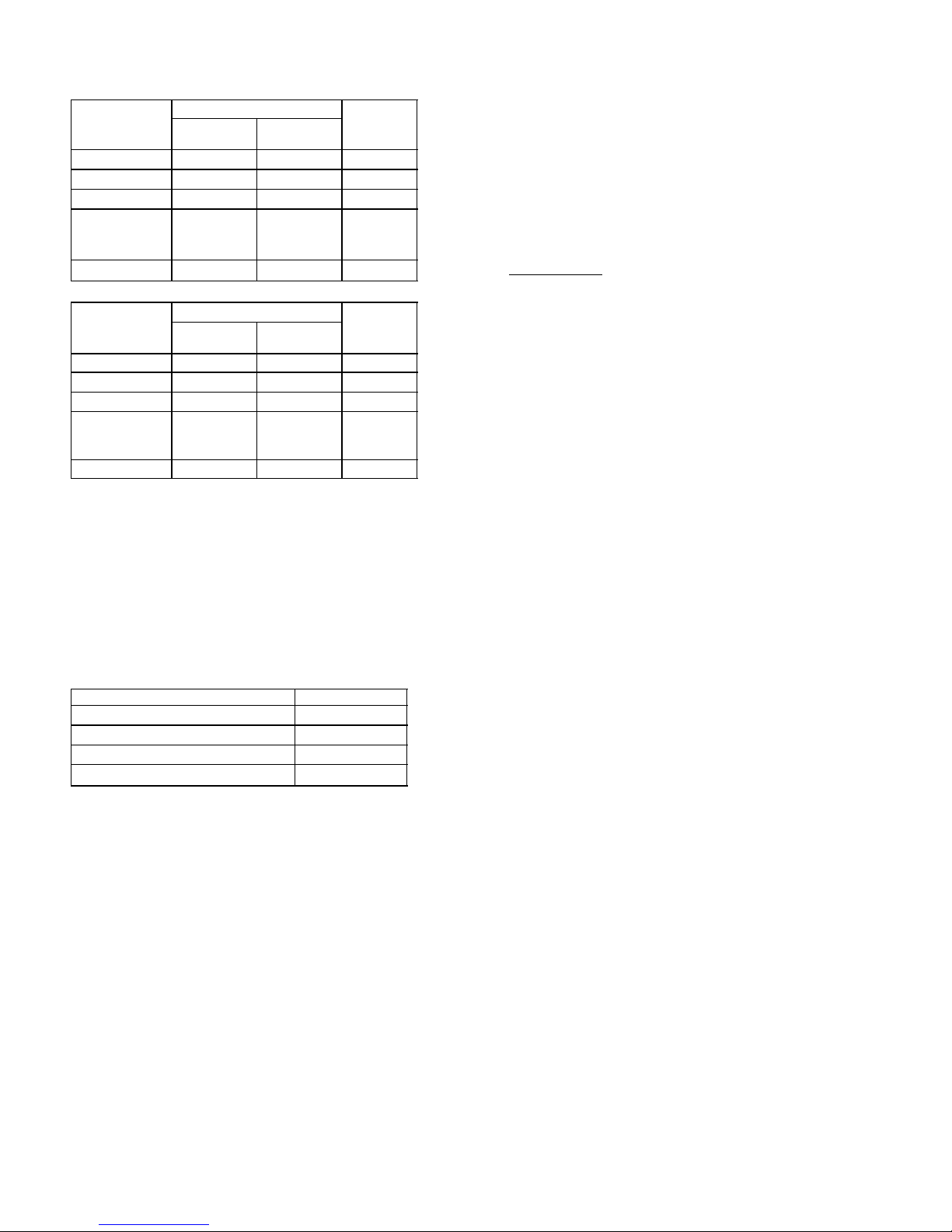
The M367 is designed for low current consumption. Under typ-
ical (+4 dBm into 600 Ω in continuous use; no phantom–powered
microphones, meter illumination or headphones in use) and with
two fresh 9–volt alkaline batteries, the M367 will operate for
about eight hours before the Power LED flashes. At this point,
about 30 minutes of battery life remains. If more mixer features
are used (Phantom–powered microphones, continuous headphones monitoring, or constant meter illumination), battery life
will decrease accordingly (see table).
Mixer Operation Battery
(A) No signal, phantom–powered mics,
headphones or meter illumination
(B) As in (A) with +4 dBm continuous output
(C) As in (B) with six Shure SM81 mics at
12 V phantom power
(D) As in (B) with six Shure SM81 mics at
48 V phantom power
(E) As in (B) with 300 Ω headphones driven moderately loud (Phones control at “5”)
(F) As in (B) with meter illumination continuously on (DIP switch position 6 closed
and Batt Check switch pressed once)
*until Power LED begins to flash, allowing about 30 minutes to replace
batteries.
Current
(mA)
40 9
45 8
55 6.5
70 5
50 7
75 4.5
Battery
Life
(hours)*
Momentary use of headphones or meter illumination will not
appreciably affect battery life.
NOTE:
The M367 draws insignificant current (6 µA) from the
batteries when the mixer is turned off and batteries are installed.
Batteries left in the M367 will retain their charge up to their shelf
life.However, long–term storage of batteries in the M367 is not
recommended.
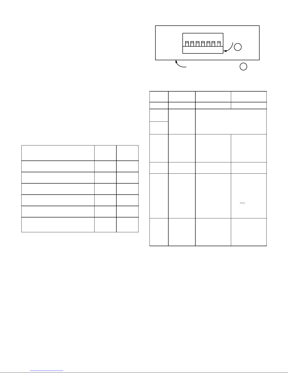
INTERNAL SWITCHES AND CONTROLS (Figure 4)
The M367 contains internal switches and adjustments that are
accessed through removal of the battery compartment and top
cover. These functions are described in the following paragraphs.
2. Battery Compartment DIP Switches S701: Remove the bat-
tery compartment. This exposes the DIP switch assembly . T h e
switches provide the options in the following table (“up” is the
switch–open position; position shown in bold type is factory
setting).
NOTE:
Switch positions and ef fects are also shown on the la-
bel on the mixer cover.
(MIXER
SIDE
VIEW)
1 2 3 4 5 6 7
BATTERY COMPARTMENT
DIP SWITCH
S701
2
1
INTERNAL DIP SWITCHES
FIGURE 4
DIP SWITCH S701 FUNCTIONS
Switch
Position
1 Meter 0 VU 0 VU = +4 dBm 0 VU = +8 dBm
2
3
4 Program to
5 Monitor In
6 VU Lamp Timed (turns on/off
7 Phantom
Switch
Function
Limiter
Threshold 2 Up + 3 Down = +4 dBm
Monitor
Gain
Power
Switch Up Switch Down
2 Up + 3 Up = +16 dBm
2 Down + 3 Up = +8 dBm
2 Down + 3 Down = 0 dBm
Off On (provides atte-
Normal High
when front panel
Batt Check switch
is activated. If not
manually switched
off, lamp will auto-
matically turn off
after 10 seconds to
conserve battery
life.)
12 Vdc phantom
power to all input
channels if se-
lected
and
panel Phantom
rear–
switch is on.
nuated program
signal in head-
phones with Pull/
Monitor switch on
[pulled outward])
Toggled (turns on/
off when front pan-
el Batt Check
switch is toggled.
Automatic timed
turnoff of lamp will
not occur.)
48 Vdc phantom
power to all input
channels if se-
lected
panel Phantom
switch is on.
and
rear–
M367 SETUP
To prepare the M367 mixer for operation, proceed as follows:
1. For ac operation, attach the supplied power cord to the rear–
panel ac connector and to a 100 to 120 Vac, 50/60 Hz
grounded (3–pin) power source. If desired, select functional
options by removing the battery compartment and activating
the exposed DIP switches (condenser microphone power, limiter threshold, etc.). Reinsert and secure the battery compartment.
2. For internal battery operation, remove the battery compartment. Install two 9 V alkaline batteries, making sure polarity
(+/–) is correct (batteries will not seat correctly unless polarity
is correct). Select functional options using the DIP switches
(condenser microphone power, limiter threshold, etc.) Reinsert and secure the battery compartment.
NOTE:
The VU meter is illuminated during ac operation. To illuminate the VU meter during battery operation, press the front–
panel Batt Check switch: If the internal VU Meter DIP switch is
in the factory–set Timed position, the VU meter will illuminate
for 10 seconds and then turn off. If the switch has been set to
the Toggled position, the meter will illuminate after pressing the
Batt Check switch and remain on until the Batt Check switch is
4
Page 5

pressed again. (Note that this mode will drain batteries faster
than the Timed mode.)
3. If greater clearance for the Input Channel 1 Gain knob is desired, the left end cap can be removed, rotated 180°, and replaced. Note that in this configuration, the end cap will not protect the gain knobs if the mixer is dropped.
4. Connect microphones, wireless microphone receivers, or other audio sources to the desired Input channel connectors on
the rear panel.
5. Position each Mic/Line Input switch based on the level of the
incoming source.
6. Connect the amplifiers, camcorders, DAT machines, wireless
microphone transmitters, or other equipment to the Output
XLR connectors on the rear panel.
7. Position the Mic/Line Output switch based on the input level
requirements of the equipment connected to the switched
M367 output (the other output is Line Level only).
8. If a “tape return” or Monitor In feed into the M367 is required,
connect a phone plug to the rear–panel Monitor In connector.
The signal on this connector typically comes from the audio
output of the device being fed by the M367.
9. Plug headphones into the stereo 1/4 in. or 3.5 mm mini
Phones jacks on the right side of the front panel.
NOTE:
The two Phones output connectors may be used separately, simultaneously, or as auxiliary feeds to other equipment.
10. To interconnect two M367 or other Shure mixers, plug a singleshielded mix bus cable into the Mix Bus connectors of both
mixers (Figure 3).
NOTE:
When two M367 mixers are interconnected via the Mix
Bus, the Master gain on either mixer can be adjusted without
affecting the other mixer’s output level. This provides the
equivalent of a 12–input mixer with two separate Master output
sections.
11. Set the Master gain, Phones volume, and all Input gains fully
counterclockwise (off).
OPERATION
To operate the M367 microphone mixer, proceed as follows:
1. Apply power to the mixer by sliding the On/Off switch to the
right. The green Power LED will illuminate to indicate that the
mixer is turned on.
2. Check the mixer battery power status by depressing the front–
panel Battery Check switch. The VU meter needle will swing
between 0 and +3 VU. If the needle falls below 0 VU, less than
30 minutes of battery power operation remain.
3. Push the front–panel Phones knob inward to route the M367
audio to the headphones.
4. Slide the Limiter slide switch to the On position to protect
against output overload.
5. Position the Low–Cut Filter slide switches for each Input: UP
for flat; DOWN for low–cut on.
6. Set the Master Gain knob to the “0 dB” position
(2 o’clock). This provides unity gain for output stages.
7. Activate the 1 kHz tone oscillator by pulling the Input 1 gain
knob outward. Adjust the Input 1 gain until the VU meter
needle indicates “0”. Adjust the input levels on the equipment
connected to the M367 outputs accordingly . Push in the Input
1 knob to turn off the tone.
8. Put on headphones and carefully adjust Phones volume control
to a comfortable list ening level.
The headphones circuit is capable of producing high
WARNING
volume levels that can damage the user’s hearing.
Make sure the headphones volume setting is low (full
CCW) before putting the headphones on.
9. Adjust the Input gain controls based on the incoming signal
levels. The Input Peak LEDs should flicker red only on loud input peaks.
10. Observe the output on the VU meter and adjust the Master
gain to obtain the desired levels. T ry to keep the average levels
around “0 VU”. The Peak LED adjacent to the VU meter should
illuminate only on loud output peaks.
The M367 mixer is now ready for use.
Connecting M367 Outputs to Telephone Lines
In the Line position, the transformer–balanced XLR outputs
can be used to drive dc–biased, “dialed up” telephone lines, although there may be a slight increase in distortion. Use of the
M367 limiter circuit is strongly advised with the limiter threshold
set to +4 dBm. Modification of the M367 output impedance to
600 Ω is recommended for proper fidelity. (See the
fiable Functions
section for instructions.) When connecting the
Internal Modi-
M367 to a telephone line, an FCC–Registered interface adapter
between the mixer and telephone line is mandatory.
SUPPLIED ACCESSORIES AND REPLACEMENT PARTS
Foot Kit (4 in kit) 90S8100. . . . . . . . . . . . . . . . . . . . . . . . . . . . . . .
Fuse, 0.125 A, 250 V, Time Delay (M367) 80E380. . . . . . . . . .
Fuse, 0.063 A, 250 V, Time Delay (M367E) 80G380. . . . . . . . .
Knob, Master 95A8238. . . . . . . . . . . . . . . . . . . . . . . . . . . . . . . . .
Knob, Channel Gain, Phones 95B8238. . . . . . . . . . . . . . . . . . . .
Line (Power) Cord, (M367) 95A8389. . . . . . . . . . . . . . . . . . . . . .
Line (Power) Cord, (M367E) 95B8389. . . . . . . . . . . . . . . . . . . . .
OPTIONAL ACCESSORY
Rack Mount Kit A367R. . . . . . . . . . . . . . . . . . . . . . . . . . . . . . . . . .
SPECIFICATIONS
Measurement conditions (unless otherwise specified): operat-
ing voltage 120 Vac, 60 Hz (18
±
1 Vdc for dc test); operating temperature 22°C (72°F); input signal 1 kHz; internal DIP switches
1–7 open; Power switch on; Mic/Line switches to Line; low–cut
switches to flat; Limiter out; Phantom power off; Mix Bus to M367;
channel 1 gain full CW; channel 2 through 6 full CCW; Master full
CW; Phones level full CCW; Line output terminations 600
2 and 3); Mic output terminations 150
Ω
(pins 2 and 3); Phones
Ω
(pins
(1/4”—ring) 300 Ω to ground; Phones (1/4”—tip) 300 Ω to ground;
Phones (3.5 mm) unloaded; Mix Bus 930
Ω
(M367 position)or 3.5
kΩ (M267 position), not connected unless specified; 1 kHz input
signal.
Frequency Response
20 to 20,000 Hz ± 2.0 dB (channel controls centered)
Total Harmonic Distortion
0.25% THD at +4 dBm output, 55 to 20,000 Hz
V oltage Gain
Output
Input Line Mic Phones Mix
Low–Z
Mic
(150 Ω)
Line 37 dB –1 1 dB 53 dB 15 dB –25 dB
Monitor ––
Mix Bus
(M367)
Mix Bus
(M267)
87 dB 40 dB 103 dB 66 dB 27 dB
––
10 dB –38 dB 26 dB –– ––
50 dB 2 dB 66 dB –– ––
12 dB –– ––
Bus
(M367)
Mix
Bus
(M267)
5
Page 6
Inputs
IMPEDANCE Input
Input Designed
for Use With
Mic 19 to 600 Ω 1 kΩ –10 dBV
Line ≤10 kΩ 50 kΩ +36 dBV
Monitor ≤1 kΩ 13 kΩ 0 dBV
Mix Bus (M367) 930 Ω bal.;
1860 Ω un-
bal.
Mix Bus (M267) 3.5 kΩ 3.5 kΩ –17 dBV
Actual
(Internal)
930 Ω bal.;
1860 Ω un-
bal.
Clipping
Level
+23 dBV
Outputs
IMPEDANCE Output
Output Designed
for Use With
Mic Low–Z inputs 1 Ω –31 dBV
Line 600 Ω 150 Ω +18 dBm
Phones 8 to 200 Ω 300 Ω +1 1 dBV
Mix Bus (M367) 930 Ω bal.;
1860 Ω un-
bal.
Mix Bus (M267) 3.5 kΩ 3.5 kΩ –28 dBV
Actual
(Internal)
930 Ω bal.;
1860 Ω un-
bal.
Clipping
Level
+11 dBV
Equivalent Input Noise
≤ –127 dBV with 150 Ω source, 400 to 20,000 Hz
Output Noise
Master level full CCW: –100 dBV, 400 to 20,000 Hz
Master level full CW: –80 dBV, 400 to 20,000 Hz
Hum and Noise
Equivalent Input: ≤125 dBV, 20 to 20,000 Hz
Output: –95 dBV (Master CCW); –75 dBV (Master CW), 20 to
20,000 Hz
Common Mode Rejection Ratio
65 dB at 100 Hz, –20 dBV input
Polarity
Mic/Line In to Mic/Line Out Non–Inverting
Mic/Line In to Phones Non–Inverting
Mic/Line In to Mix Bus (tip) Inverting
Monitor to Phones Non–Inverting
Mix Bus to Mic/Line Out Inverting
Overload and Shorting
Shorted outputs, even for prolonged periods, cause no damage. Microphone inputs of up to 3 Vrms cause no damage.
Line and monitor can withstand signals of up to 30 Vrms.
Input Peak Indicat ors
6 dB below clipping level
Output Peak Indicator
Lights red at 6 dB below clipping level
Output Clipping Level
≥ +18 dBm at line output into 600 Ω
Low–Cut Filters
7 dB down at 150 Hz; 6 dB/octave slope (3 dB down at 260 Hz)
Tone Oscillator
1 kHz ± 20%
Limiter
Threshold: Switchable: 0, +4, +8, +16 dBm
Attack Time: 1 ms ±0.5 ms
Release Time Constant: 100 ms ± 30 ms
Indicator: Green when limiting by 1 dB or more
Phantom Power
12 V Phantom: 12 V through 340 Ω
48 V Phantom : 48 V through 3.4 kΩ
Mixer Power
AC.
M367: 100–120 Vac, 50/60 Hz, 100 mA (can be rewired
for 220–240 V ac operation); M367E: 220–240 Vac, 50/60 Hz,
50 mA (can be rewired for 100–120 Vac operation); no–signal
current drain 25 mA
DC; meter illumination off. 18 Vdc nominal at 40 mA typical
no–signal, 45 m A typical at +4 dBm output; 13.5 Vdc minimum;
battery life approximately 8 hours at +4 dBm output in continuous use.*
*Meter not illuminated; no phantom microphones; no headphones.
DC; meter illumination on. 18 Vdc nominal at 70 mA typical
no–signal, 75 m A typical at +4 dBm output; 13.5 Vdc minimum;
battery life approximately 4 hours at +4 dBm output in continuous use.
Batteries. Two 9 V alkaline batteries, type NEDA 1604A (Duracell MN1604 or Eveready 522 recommended)
T emperature Range
Operating: –18° to 57° C (0° to 135° F)
Storage: –29° to 74° C (–20° to 165° F)
Overall Dimensions (H x W x D)
71.9 mm x 308 mm x 233 mm (2
13
/16” x 125/32” x 95/32”) includ-
ing feet
Weight (without batteries)
3 kg (6.6 lb)
ST ATEMENT OF CONFORMITY
This certifies that the Shure M367E Microphone Mixer meets
the specifications and regulations embodied in Vfg 243/1991,
amended 1992. The Bundesamt für Zulassungen in der Telekommunikation has been notified that this device has been marketed and has been provided the right to verify the device or system for compliance with the specifications.
Conforms to European Union directives, eligible to bear CE
marking; VDE GS-Certified to EN 60 950; meets European Union
EMC Immunity Requirements (EN 50 082–1, 1992): RF radiated
(IEC 801–3): meets Criterion A, ESD: meets Criterion B, EFT
(IEC 801–4): meets Criterion B
INFORMATION TO USER
Changes or modifications not expressly approved by Shure
Brothers Inc. could void your authority to operate this equipment.
This equipment has been tested and found to comply with the
limits for a Class B digital device pursuant to Part 15 of the FCC
Rules and as set out in the Radio Interference Regulations of the
Canadian Department of Communications. These limits are designed to provide reasonable protection against harmful interference in a residential installation. This equipment generates,
uses, and can radiate radio frequency energy and, if not installed
and used in accordance with the instructions, may cause harmful
interference to radio communications. However, there is no guarantee that interference will not occur in a particular installation.
If this equipment does cause harmful interference to radio or television reception, which can be determined by turning the equipment of f and on, the user is encouraged to try to correct the interference by one or more of the following measures:
1. Reorient or relocate the receiving antenna.
2. Increase the separation between the equipment and receiver.
3. Connect the equipment into an outlet on a circuit different from
that to which the receiver is connected.
4. Consult the dealer or an experienced radio/TV technician for
help.
6
Page 7
INTERNAL ADJUSTMENTS
WARNING
All internal adjustments must be performed by
qualified service technicians.
NOTE:
All internal adjustments require only removal of the top
cover.
1. Remove battery compartment.
2. Remove four screws securing two plastic end caps and one
ground–bonding screw on the side opposite the battery
compartment.
3. Slowly slide cover up and off chassis.
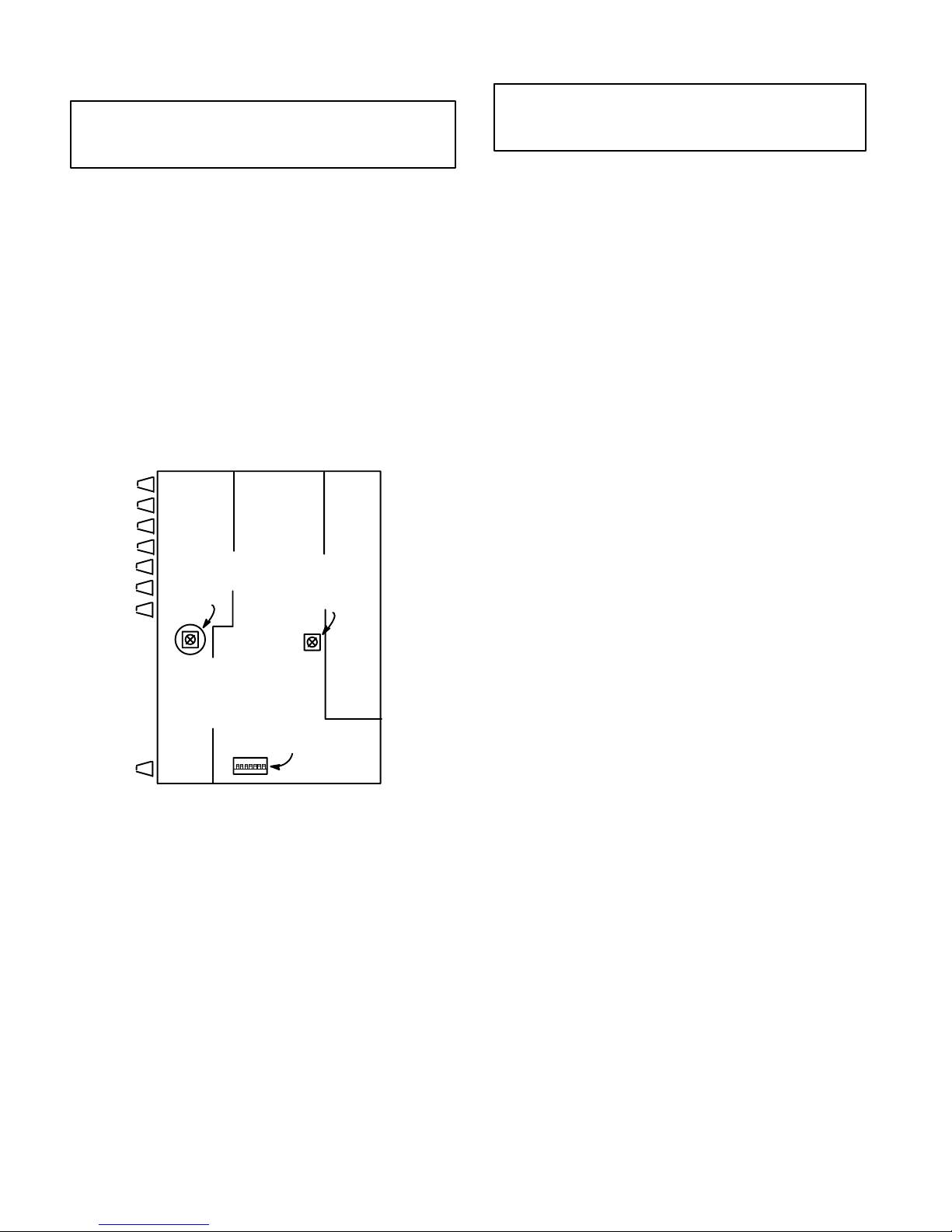
VCA Distortion Factory Preset Potentiometer R607 (see
Figure 5)
DO NOT ADJUST! This potentiometer is precisely calibrated
on each mixer for minimum distortion.
VU Meter Adjustment (see Figure 5)
This trimpot adjusts the VU meter to indicate 0 VU at a preset
output level. The factory setting is +4 dBm. The user adjustment
range is –10 dBV to +4 dBm (–6 dBV to +8 dBm with DIP switch
1 down.
VU METER
CALIBRATION
TRIMPOT
R684
(ACCESSED
THROUGH
HOLE IN
UPPER FRONT
PC BOARD)
DIP SWITCH
VCA
DISTORTION
TRIMPOT
R607
S701
INTERNAL ADJUSTMENTS
FIGURE 5
T o set the VU meter to a value other than the factory setting (0
VU = +4 dBm), proceed as follows:
1. Connect a 600 Ω load to an XLR output set for Line.
2. Connect an ac voltmeter with 1 MΩ or greater input impedance
(Fluke 77 or equivalent) in parallel with the load.
3. Pull out the channel 1 Gain knob to activate the 1 kHz tone oscillator.
4. Adjust the 1 kHz tone oscillator level with the Master gain control until the ac voltmeter reading is at the level desired.
5. With the M367 top cover removed, adjust the VU Level Calibration trim pot R684 with a screwdriver until the VU Meter
reads 0.
6. For 0 VU settings between +4 and +8 dBm, set internal DIP
switch S701 position 1 “down”, and perform steps 1 through 5.
INTERNAL MODIFIABLE FUNCTIONS
Selected internal functions of the M367 can be modified by the
user to fit special applications. All modifications are performed
through solder points accessible on the main PC board. Procedures for performing these modifications are listed below.
All internal modifications must be performed by
WARNING
qualified service technicians.
Disassembling the M367
1. Remove the mixer top cover as described above.
2. Carefully remove three multi–pin cable assembly connectors
from upper front PC board (nearest front panel).Remove three
Phillips head screws which secure PC board. Remove upper
front PC board.
3. Carefully remove four multi–pin cable assembly connectors
from upper rear PC board (nearest rear panel).Remove three
Phillips head screws which secure PC board. Remove upper
rear PC board.
4. Perform modification (refer to appropriate procedure below).
Note that all modifications can be performed without removing
the main PC board.
5. Reassemble M367 by performing above steps in reverse, assembling the Phillips screws in the order indicated on the upper front and upper rear PC boards.
Changing Operating Voltage Range
The M367 and M367E can be internally modified for an alter-
nate operating range.
M367 Operation at 220–240 Vac
1. Disconnect the ac power and remove the mixer top cover as
described above.
2. Locate Voltage Selector switch S301 adjacent to power transformer T301. Use a screwdriver to move the center dial so
“230” is opposite the indicator. Replace the top cover.
3. Open the rear–panel fuse compartment and replace the 0.125
mA, 250 V fuses (operating and spare) with 0.063 mA, 250 V
fuses of the same size and type. Close the fuse compartment.
M367E Operation at 100–120 Vac
1. Disconnect the ac power and remove the mixer top cover as
described above.
2. Locate Voltage Selector switch S301 adjacent to power transformer T301. Use a screwdriver to move the center dial so
“115” is opposite the indicator. Replace the top cover.
3. Open the rear–panel fuse compartment and replace the 0.063
mA, 250 V fuses (operating and spare) with 0.125 mA, 250 V
fuses of the same size and type. Close the fuse compartment.
Changing Line Level Output Impedance to 600Ω
1. Locate resistor R621 (near IC U602 pin 8) on main PC board
and remove it.
2. Locate empty pads X621 (near resistor R621).
3. Solder a 430 Ω,
1
/2W resistor through the holes at X621.
Changing Unswitched Line Output to Mic Level
1. Locate resistor R632 (near output transformer T601) and remove.
2. Locate empty pads X632 (near transformer T601).
3. Solder a jumper wire through the holes of X632.
Changing Mixer Audio Levels in Headphones (Pull/Monitor Switch Activated, DIP Switch S701 Position 4 Closed)
1. Locate empty pads X649 (near Phones potentiometer R648).
2. Solder a 68 kΩ,
1
/4 W resistor through the holes at X649 to hear
program audio 12 dB down from standard headphones level
with Pull/Monitor switch on (pulled out).
3. Solder a 24 kΩ,
1
/4 W resistor through the holes at X649 to hear
program audio 6 dB from standard headphones level with Pull/
Monitor switch on (pulled out).
7
Page 8
Changing Low–Cut Filter Corner Frequency (3 dB down
point)
A. To
decrease
corner frequency:
1. Calculate new capacitor value for lower low–cut corner frequency. Use the following formula:
C in µF= (85/frequency) – 0.33
Example: for 200 Hz corner frequency,
85/200 ≈ 0.43
0.43 – 0.33 = 0.1
For 200 Hz corner frequency, use a 0.1 µF capacitor.
Note:
Capacitor must be non–polarized; ceramic or film type;
16V rating or higher.
2. Locate the following empty pads:
Pad Channel Pad Channel
X421 1 X451 4
X431 2 X521 5
X441 3 X531 6
All pads are found near ribbon cable assemblies W81 1, W812
and W813.
3. Solder a new capacitor through the holes of the empty pads
for each channel to be modified.
B. To
increase
Note:
corner frequency:
Low–cut corner frequencies much higher than the factory preset of 260 Hz may excessively attenuate desired low– to
mid–frequency program material.
1. Locate the following capacitors near empty pads:
Capacitor Pad Channel Capacitor Pad Channel
C425 X421 1 C455 X451 4
C435 X431 2 C525 X521 5
C445 X441 3 C535 X531 6
2. Remove the indicated capacitor for each channel to be modified.
3. Calculate new capacitor value for higher high–cut corner frequency. Use the following formula:
C in µF= (85/frequency)
Example: for 400 Hz corner frequency,
C = (85/400) = 0.21
For 400 Hz corner frequency, use a 0.22 µF capacitor.
4. Solder a new capacitor through the holes of the empty pads
for each channel to be modified.
Slowing Output Level Meter from “True VU” Ballistics
1. Locate empty pads X691 (at left of VU meter M1).
2. Solder a 100 µF x 6.3 V electrolytic capacitor through the holes
of X691. Observe capacitor polarity as marked on the PC
board. The response time is now 500 ms with no overshoot.
3. To slow the meter response even further, use a larger capacitor
value.
Changing Mic Level Output Impedance
1. Locate resistor R631 (near output transformer T601) and remove it.
2. Locate empty pads X631 (near T601).
3. Solder desired value
For example, use a 150 Ω,
1
/4 W resistor through the holes of X631.
1
/4 W resistor for 150 Ω output im-
pedance.
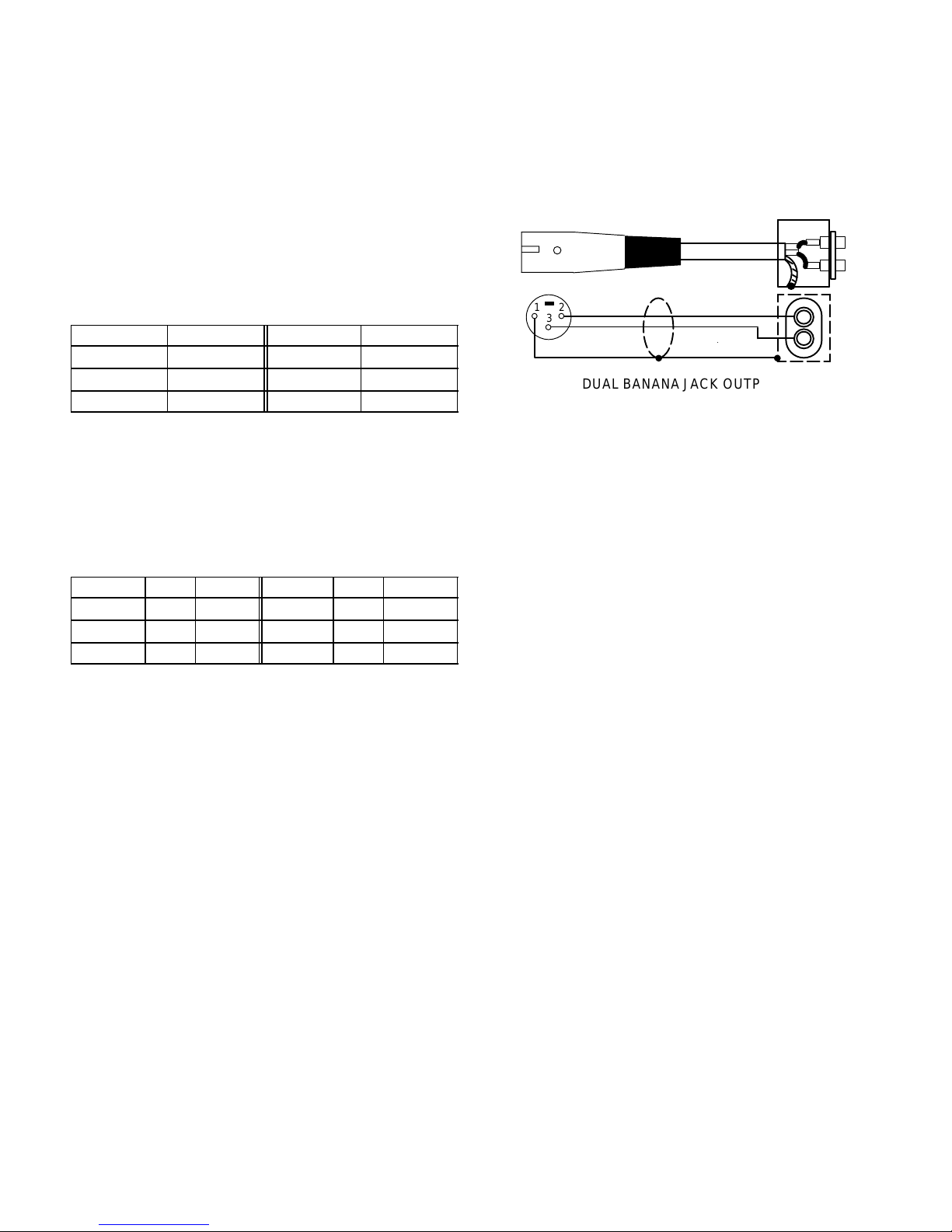
Adapting Line Out to Dual Banana Jack
Adding a dual banana jack, balanced, line–level output capability can be accomplished by purchasing a commercial unit
(Sescom XLR F–3BP or equivalent), or obtaining a female XLR
connector (Radio Shack 274–011 or equivalent), a dual banana
jack (ITT 2269 or equivalent), a small utility box, and a short
length of high–quality shielded output cable and constructing the
adapter shown in Figure 6.
231
DUAL BANANA JACK OUTPUT
FIGURE 6
Connect this adapter to the M367 Line output.
Changing Monitor In to Aux In
Note:
This modification will disable the M367’s monitor func-
tion.
1. Locate and remove resistors R642 and R647 (near Phones
potentiometer R648).
2. Locate empty pads X601 (near output transformer T601) and
X643 (near Monitor In jack J683).
3. Solder a jumper wire from X643 to X601. The Monitor In jack
is now an unbalanced (tip positive, sleeve ground) Aux In jack,
with an input impedance of 11 kΩ and a maximum gain to Line
Out (loaded with 600 Ω) of 17 dB. The Aux In signal is only con-
trolled by the Master control.
4. To change Aux In gain, locate resistor R605 (near X601). Care-
fully remove R605 and replace it with a surface–mount resistor
(0805 package) of the desired value. If R605 is replaced with
15 kΩ, maximum Aux In to Line Out gain will be 14 dB and input
impedance will be 16 kΩ; if it is replaced with 6.8 kΩ, maximum
Aux In to Line Out gain will be 20 dB and input impedance will
be 7.8 kΩ.
Changing Monitor In High Gain (DIP Switch S701 Position
5 Down)
1. Locate resistor R647 (near Phones potentiometer R648) and
remove it.
2. Locate empty pads X647 (near R647).
3. Solder a 330 Ω,
1
/4 W resistor in the holes of X647 for 6 dB gain
boost with DIP switch S701 position 5 down (input impedance
will be 6.5 kΩ in this position).
Changing Monitor In Jack from Mono Input to Stereo Sum
Input
1. Locate empty pads X645 (near Monitor In jack J863).
2. Solder a 1 kΩ, 1%,
1
/4 W resistor in the holes of X645. The Monitor In jack will now accept a stereo input signal (tip left, ring
right, sleeve ground), and sum these signals to the monitor circuit.
Note:
If a true stereo feed is used to drive the M367 Monitor In
and another stereo device, the source impedance must be 20 Ω
or less to maintain at least 40 dB separation in the stereo device.
Use a stereo distribution amplifier or buffer to maintain optimum
stereo separation.
8
Page 9
Master Gain Remote Control
Note:
function
This modification will disable both the M367’s monitor
and
its front–panel Master gain control,
1. Locate resistor R641 (near Monitor In jack J863) and remove
it.
2. Locate resistor R746 (near Master potentiometer R706) and
remove it.
3. Locate empty pad X702 (near Master potentiometer R706).
Solder one end of a 100 Ω,
1
/4 W resistor in the hole of X702.
Solder an insulated wire to the other end of the 100 Ω resistor.
Locate empty pad X644 (near jack J863). Solder the other end
of the insulated wire to X644.
4. Locate empty pad X701 (next to empty pad X702). Solder an
insulated wire to X701. Locate empty pads X645 (near jack
J863). Solder the other end of the insulated wire to the empty
pad X645 nearest channel 6 input connector J856.
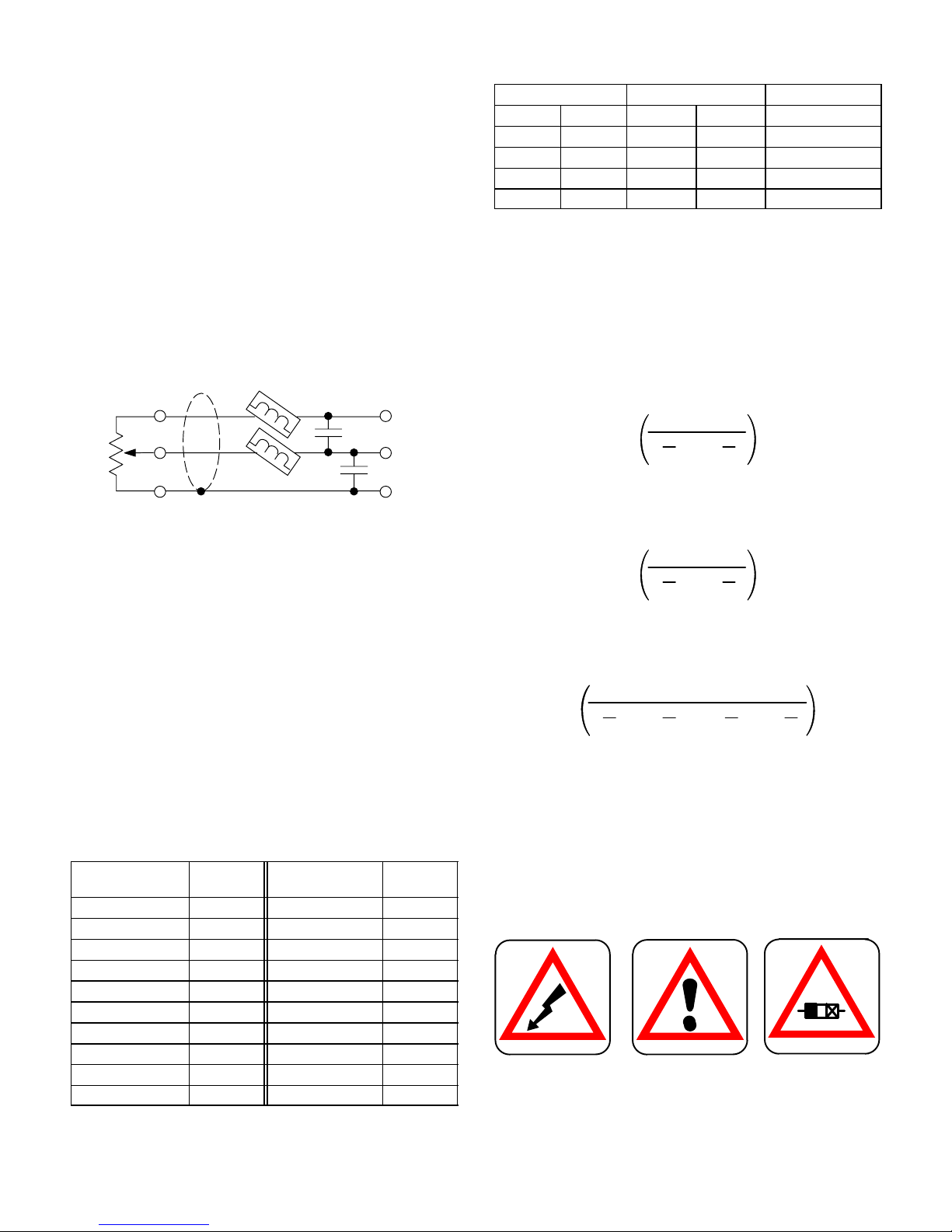
5. Construct a remote control potentiometer/cable assembly as
shown in Figure 7.
TIP
RING
CW
SLEEVE
MASTER GAIN REMOTE CONTROL
FIGURE 7
Recommended parts are:
Potentiometer, 10–25 kΩ, linear taper (Radio Shack
271–1715)
1
/4–Inch Stereo Phone Plug (Switchcraft 280)
Ferrite Bead Rings (Ferronics 21–031J)
Capacitors, ceramic, 0.001 µF, 50 V
Cable, 2–conductor, shielded, 50 ft maximum
Ferrite bead rings and capacitors should be as close to the
phone plug as possible.
6. Insert the phone plug in the Monitor In jack. The remote control
potentiometer now controls M367 gain with a control taper
similar to that of the Master gain control.
Changing Limiter Release Time to One Second
1. Locate resistor R741 (about 15 mm behind ribbon cable assembly W813) and remove it.
Changing Limiter Threshold Presets
1. Determine the desired limiter thresholds and select the equivalent resistor values from the following table. Then fill in the
worksheet that follows with the resistor selections.
Limiter Threshold
(dBm into 600 Ω)
0 18 10 81
1 21 11 93
2 25 12 105
3 30 13 122
4 35 14 139
5 41 15 156
6 47 16 175
7 54 17 194
8 62 18 215
9 71
R
(kΩ) Limiter Threshold
equiv
(dBm into 600 Ω)
R
equiv
(kΩ)
DIP Switch S701 Limiter Threshold R
Position 2 Position 3
up up high _____ _____kΩ = R1
down up med. high _____ _____kΩ = R2
up down med. low _____ _____kΩ = R3
down down low _____ _____kΩ = R4
—
dBm
equiv
(above)
—
2. Locate resistors R721, R731, R732, R733, R734 and R735
(surrounding IC U704) and remove them.
3. Locate empty pads X732, X733, X734 and X735 (surrounding
IC U704).
4. Select a
1
/4 W, 1% resistor closest in value to R1 (from the
worksheet), and solder it to the holes of X732.
Note:
Use parallel or series combinations of resistors to match
the chosen values as closely as possible if 1% resistors are not
available.
5. Calculate resistor R5 value as follows:
R5 =
1
R2
1
1
–
R1
Select a 1/4 W, 1% resistor closest in value to R5 and solder
it to the holes of X733.
6. Calculate resistor R6 value as follows:
R6 =
1
R3
1
1
–
R1
Select a 1/4 W, 1% resistor closest in value to R6 and solder
it to the holes of X734.
7. Calculate resistor R7 value as follows:
R7 =
Select a
1
–
R4
1
/4 W, 1% resistor closest in value to R7 and solder
1
R1
1
1
–
R5
1
–
R6
it to the holes of X735.
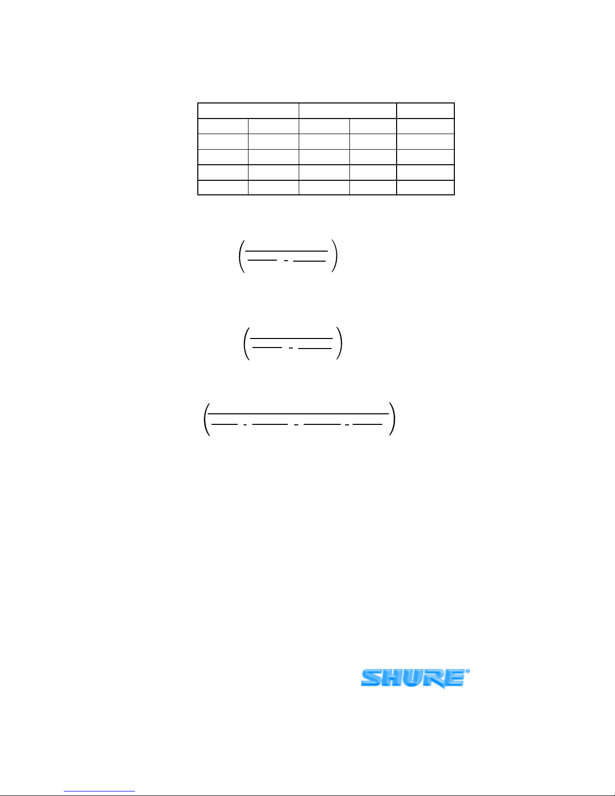
An example of limiter threshold preset component calculations
is given in the
Appendix
.
Graphic SymbolsThe M367 rear panel contains graphic symbols with the following meanings (see Figure 8). (A) indicates
the presence of dangerous voltage. (B) indicates that the user
should consult the instruction manual for explanatory material.
(C) indicates that a replacement fuse must be of the same
rating and type.
(A) (B) (C)
GRAPHIC SYMBOLS
FIGURE 8
9
Page 10
APPENDIX
Changing Limiter Threshold Presets: Samples Calculations
For the following limiter thresholds:
DIP Switch S701
Position 2 Position 3 — dBm —
up up high 12 105 kΩ=R1
down up med. high 8 62 kΩ=R2
up down med. low 4 35 kΩ=R3
down down low 0 18 kΩ=R4
1. Obtain a 105 kΩ, 1/4 Ω, 1% resistor and solder it to the holes of X732.
2.
R
5 =
1
62,000
Obtain a 150 kΩ, 1/4 W, 1% resistor and solder it to the holes of X733.
3.
R
6 =
1
35,000
Obtain a 52.3 kΩ, 1/4 W, 1% resistor and solder it to the holes of X734.
Limiter Threshold R
1
1
105,000
1
1
105,000
equiv
= 151.4 kΩ
= 52.5 kΩ
4.
1
7 =
11
105,000
1
150,000
1
52,30018,000
= 49.4 kΩR
Obtain a 49.9 kΩ, 1/4 W, 1% resistor and solder it to the holes of X735.
SHURE Incorporated Web Address: http://www.shure.com
222 Hartrey Avenue, Evanston, IL 60202–3696, U.S.A.
Phone: 847-866–2200 Fax: 847-866-2279
In Europe, Phone: 49-7131-72140 Fax: 49-7131-721414
In Asia, Phone: 852-2893-4290 Fax: 852-2893-4055
Elsewhere, Phone: 847-866–2200 Fax: 847-866-2585
10
 Loading...