

Page 1

LX Wireless System
LX Wireless System
User Guide
©2003, Shure Incorporated
27D8654 (Rev. 6)
Printed in U.S.A.
Page 2

LX Wireless System
READ ME FIRST!
To get your system up and running in just a few minutes, follow the simple instructions on this page. For more detailed information, refer to the sections of
this guide that apply to your system.
RECEIVER CONNECTIONS
1. Attach the antennas to the receiver antenna connectors.
2. Connect the AC power adapter to the receiver power connector; then plug it into an
ac electrical outlet.
3. Connect the receiver audio output to the sound system, using either a low- or
high-impedance audio cable.
TRANSMITTER CONNECTIONS
1. Open the transmitter battery compartment and insert a fresh 9-volt alkaline battery.
Observe proper battery polarity ( “+/–”).
2. If you are using a body-pack transmitter, connect the microphone or WA302 instru-
ment cable to the 4-pin connector on the transmitter.
OPERATING THE SYSTEM
1. Press the receiver POWER switch. The green POWER light on the receiver
illuminates.
2. Set the transmitter PWR/OFF switch to PWR and the ON/MUTE switch to ON. One
of the three lights on the transmitter illuminates, indicating both that the transmitter
is on and the amount of battery life remaining. Two sets of five RF level lights on
the receiver will also glow to indicate the strength of the received signal. The more
lights glowing, the stronger the signal.
3. Have someone talk or sing into the microphone, or play the musical instrument
connected to the transmitter. The audio level will be indicated as follows:
• Green lights (3) glowing indicates normal operation.
• Amber light glowing indicates approaching audio overload (should only occur
during loud signals).
• Red light glowing steadily indicates audio overload. If this happens, reduce the
transmitter gain until it flickers only during the loudest signals. Refer to the
Transmitter Audio Gain Adjustment section of this guide.
4. Adjust the receiver LEVEL control until the output level is compatible with the mixer
or amplifier input. In most cases, this control should be set fully clockwise.
YOU ARE NOW READY TO PERFORM!
IMPORTANT: Every wireless microphone installation is a unique situation,
and can present a variety of problems. Never attempt a live performance
without first conducting a “walkthrough” test of the system in the performing
area. If major changes (additional wireless systems or intercoms, relocation
of scenery, etc.) have been made since the last walk-through test, check the
wireless system again-as close to performance time as possible.
1
Page 3

English
TABLE OF CONTENTS
TABLE OF CONTENTS . . . . . . . . . . . . . . . . . . . . . . . . . . . . . . . . . . . . . .2
SYSTEM COMPONENTS . . . . . . . . . . . . . . . . . . . . . . . . . . . . . . . . . . . .3
SYSTEM FEATURES . . . . . . . . . . . . . . . . . . . . . . . . . . . . . . . . . . . . . . . .4
LX1 BODY-PACK TRANSMITTER FEATURES, CONTROLS
AND INDICATORS . . . . . . . . . . . . . . . . . . . . . . . . . . . . . . . . . . . . . . . . . .5
LX2 HANDHELD MICROPHONE-TRANSMITTER
FEATURES, CONTROLS AND INDICATORS . . . . . . . . . . . . . . . . . . . . .6
LX3 RECEIVER FEATURES, CONTROLS AND INDICATORS . . . . . . .7
LX4 DIVERSITY RECEIVER FEATURES, CONTROLS
AND INDICATORS . . . . . . . . . . . . . . . . . . . . . . . . . . . . . . . . . . . . . . . . . .8
RECEIVER MOUNTING . . . . . . . . . . . . . . . . . . . . . . . . . . . . . . . . . . . . . .9
RECEIVER CONNECTIONS . . . . . . . . . . . . . . . . . . . . . . . . . . . . . . . . .10
TRANSMITTER SETUP . . . . . . . . . . . . . . . . . . . . . . . . . . . . . . . . . . . . .11
OPERATING LX1 BODY-PACK SYSTEMS . . . . . . . . . . . . . . . . . . . . . .14
OPERATING THE LX2 HAND-HELD SYSTEM . . . . . . . . . . . . . . . . . . .15
GAIN AND SQUELCH ADJUSTMENT . . . . . . . . . . . . . . . . . . . . . . . . . .16
TIPS FOR ACHIEVING OPTIMUM PERFORMANCE . . . . . . . . . . . . . .17
TROUBLESHOOTING . . . . . . . . . . . . . . . . . . . . . . . . . . . . . . . . . . . . . .18
SPECIFICATIONS . . . . . . . . . . . . . . . . . . . . . . . . . . . . . . . . . . . . . . . . .19
LICENSING INFORMATION . . . . . . . . . . . . . . . . . . . . . . . . . . . . . . . . .22
2
Page 4
LX Wireless System
SYSTEM COMPONENTS
WIRELESS
RECEIVER
SQUELCH
LEVEL POWER
RF A RF B
AUDIO
MARCAD
DIVERSITY
LEVEL
SQUELCH
AUDIO
POWER
®
fixed frequency diversi-
RF
LX1
LX3
LX2
LX4
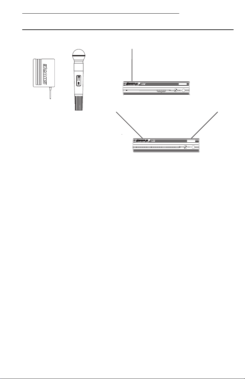
LX WIRELESS MICROPHONE SYSTEM COMPONENTS
FIGURE 1
Your LX Wireless Microphone System features a MARCAD
ty receiver operating in the VHF band between 169 and 240 MHz. Up to 12 LX wireless
systems can be operated simultaneously in a single installation. Each LX system includes:
•
LX1
Body-Pack Transmitter, with your choice of instrument cable or micro-
phone,
or
•
LX2
Hand-Held Microphone-Transmitter with your choice of interchangeable
microphone heads:
-SM58® cardioid dynamic microphone
®
- BETA 58
supercardioid premium dynamic microphone
- SM87 supercardioid condenser microphone
- BETA 87 supercardioid premium condenser microphone
and one of the following half-rack size receivers:
•
LX3
Receiver
or
•
LX4
Diversity Receiver
- Both single and dual rack-mounting hardware
- One antenna (LX3 systems) or two antennas (LX4 systems)
- One of the following ac power adapters: PS40, PS40E, or PS40UK.
3
Page 5

English
SYSTEM FEATURES
Shure LX Wireless Systems offer a number of exceptional features, including:
•
Exclusive Shure MARCAD Circuitry (LX4).
bining Audio Diversity) circuitry constantly monitors signals from both receiver
sections and combines them to create a single output signal. The result is improved reception and exceptional freedom from dropouts.
Half-Rack Receiver Size.
•
(half-rack) format, and are supplied with both single and dual rack-mount hardware. An optional WA503 accessory kit lets you front-mount antennas.
•
Power/Battery Fuel Gauge.
gauge that indicates both “power on” and the amount of battery life remaining
(see page 12).
•
Dual RF Level Meters (LX4).
LX4 receiver has two meters, one for each antenna. The dual meters indicate
received signal strength at each antenna, and make it easier to identify and troubleshoot RF “dead spots.”
Audio Metering.
•
ting and lets you monitor audio level during operation.
•
True Guitar Sound.
quality and reliability will appreciate the low noise and uncolored sound of the
LX Wireless System.
•
Noise Squelch.
This virtually eliminates the possibility of annoying noise bursts coming through
your receiver.
Body-Pack Transmitter Belt Clip.
•
a better grip, and firmly holds thinner, more slippery materials. It can be removed or inverted for special positioning.
•
Grip/Switch Cover Accessory.
cessory, supplied with all LX2 hand-held microphone-transmitters, prevents accidental movement of the power and mute switches and provides a “grip” feel.
•
Compact Power Adapter.
in-line transformers that save space on ac power strips. It also has mounting
tabs so it can be secured to any surface, as well as locking dc power connectors
to prevent accidental disconnection from the receiver.
A five-light audio meter helps to optimize transmitter gain set-
This circuit analyzes signal
The LX3 and LX4 receivers interface with the HR
The LX1 and LX2 transmitters include a three-light
Instead of a conventional single RF meter, the
Guitar players demanding the highest degree of sound
The belt clip has a wider contact surface for
The unbreakable WA555 grip/switch cover ac-
The supplied ac power adapter incorporates small,
MARCAD (MAximum Ratio Com-
quality
instead of signal
strength
.
4
Page 6
LX Wireless System
LX1 BODY-PACK TRANSMITTER FEATURES, CONTROLS
AND INDICATORS
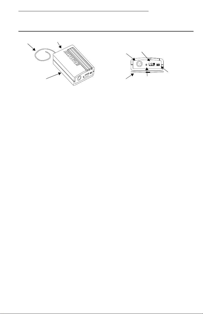
LX1 BODY-PACK TRANSMITTER FEATURES, CONTROLS AND INDICATORS
FIGURE 2
Antenna. A flexible wire antenna is permanently attached to the bottom of the LX1
body-pack transmitter. For best operation, the antenna must hang in the vertical
position, and should not be coiled or bundled.
Battery Compartment. Hinged cover on bottom surface exposes the battery.
Refer to the Body-Pack Transmitter Battery Installation section.
Audio Gain Control. Allows audio level adjustment to accommodate various
sound sources (e.g., singing, speaking, or playing an instrument). A small screwdriver is supplied to make adjustments (see the Setting Audio Level section).
Input Jack. This is a Mini- connector (TA4F) that provides connection with a vari-
ety of lavalier and headset microphone cables, and the Shure WA302 instrument
adapter cable.
Power/Battery Fuel Gauge. When the Power switch is turned to the PWR posi-
tion, one or two of the three lights on the transmitter illuminates, indicating power to
the unit. The color of the glowing light(s) indicates the amount of battery life
remaining (see page 12).
Belt Clip. Allows the transmitter to be easily worn on a belt, waistband or guitar
strap.
Mic On/Mute Switch. “Mutes” the transmitter to prevent unwanted sounds from
being picked up by the receiver without turning the transmitter off.
Power Switch. Turns transmitter power on and off.
5
Page 7
English
LX2 HANDHELD MICROPHONE-TRANSMITTER
FEATURES, CONTROLS AND INDICATORS
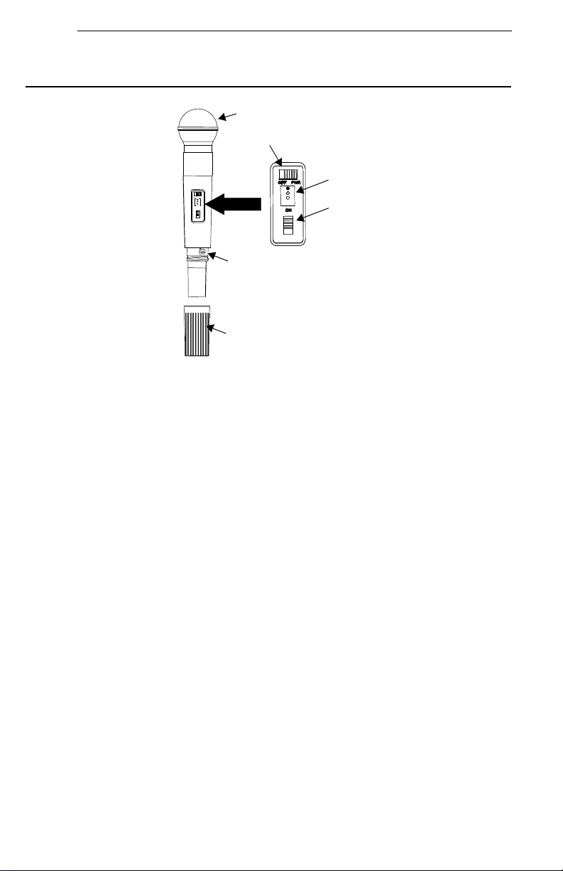
LX2 MICROPHONE-TRANSMITTER FEATURES, CONTROLS, AND INDICATORS
FIGURE 3
Grille. Protects the microphone cartridge and helps reduce breath sounds and
wind noise. The grilles for the various microphone heads differ in appearance.
Power Switch. Turns transmitter power on and off.
Power/Battery Fuel Gauge. When the Power switch is turned to the PWR posi-
tion, one or two of the three lights on the transmitter illuminates. The color of the
glowing light(s) indicates the amount of battery life remaining (see page 12).
Mic On/Mute Switch. “Mutes” the transmitter to prevent unwanted sounds from
being picked up by the receiver without turning the transmitter off.
Audio Gain Control. Provides audio level adjustment to accommodate different
sound sources (see page 16).
Battery Cover. Removable cup hides battery and audio gain control.
6
Page 8
LX Wireless System
LX3 RECEIVER FEATURES, CONTROLS AND INDICATORS
WIRELESS
FRONT
SQUELCH
RF
AUDIO
RECEIVER
LEVEL POWER
REAR
OUTPUT
I Z POWER
H
12.5 – 18.9 VDC
ANT
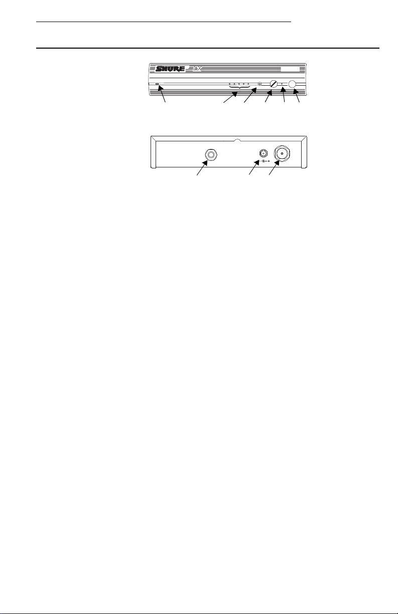
LX3 RECEIVER CONTROLS, FEATURES, AND INDICATORS
FIGURE 4
RF Presence Indicators. Glows amber when the antenna is receiving usable RF
(radio frequency) signals.
Audio Level Indicators. Five lights glow to indicate audio signal strength. Green
lights indicate normal operation. An amber light indicates approaching overload
condition. A red light indicates excessive audio levels.
Squelch Control. Sets the point at which the receiver “mutes” when the transmit-
ter signal becomes noisy, weak or fails. This control is factory-set at the 12 o'clock
position to provide optimal operation in most applications.
Audio Output Level Control. Lets you adjust output level to match the input level
requirements of a mixer or amplifier. In most situations, this control should be set
fully clockwise.
Power On Indicator. This green light glows to indicate that the Power switch is on
and power is applied to the receiver.
Power On/Off Button. Turns the receiver on and off.
Output Connector. Quarter-inch phone jack provides unbalanced auxiliary level
(high-impedance) output.
Power Jack: Accepts power from the supplied AC adapter, or from any filtered 15
to 18 Vdc (400 mA minimum) supply. It will also accept the dc power cord from a
Shure WA405 Antenna Power/Distribution System.
Antenna Connector. UHF-type connector provides connection to the supplied
1/4-wave antenna or to coax cable used with a remote antenna. They also provide
connection to the optional Shure WA421 remote antenna cable kit used with
optional WA380 telescoping and WA490 cable-type 1/2-wave antennas.
7
Page 9

English
LX4 DIVERSITY RECEIVER FEATURES, CONTROLS
AND INDICATORS
MARCAD
DIVERSITY
RF A RF B
AUDIO
SQUELCH LEVEL
POWER
HI Z
OUTPUTS
BAL
MIC LINE
POWER
– 18.9 VDC
12.5
쐅쐈
ANTANT
AB
LX4 DIVERSITY RECEIVER FEATURES, CONTROLS AND INDICATORS
FIGURE 5
Diversity Signal Indicators for A and B Antennas. These lights glow amber
when A, B, or both antennas are receiving usable RF (radio frequency) signals.
RF Level Indicators. Five lights per antenna glow to indicate RF signal strength.
The more lights that glow, the stronger the received signal. If none of these lights
glows, no signal is being received.
Audio Level Indicators. Five lights glow to indicate audio signal strength. Green
lights indicate normal operation. An amber light indicates approaching overload
condition. A red light indicates excessive audio levels.
Squelch Control. Sets the point at which the receiver “mutes” when the transmit-
ter signal becomes noisy, weak or fails. This control is factory-set at the 12 o'clock
position to provide optimal operation in most applications.
Audio Output Level Control. Lets you adjust output level to match the input level
requirements of a mixer or amplifier. In most situations, this control should be set
fully clockwise.
Power On Indicator. This green light glows to indicate that the Power switch is on
and power is applied to the receiver.
Power On/Off Button. Turns the receiver on and off.
Antenna Connectors. UHF-type connectors provide connection to the supplied
1/4-wave antennas or to coax cable used with remote antennas. They also provide
connection to the optional Shure WA421 remote antenna cable kit used with
optional WA380 telescoping and WA490 cable-type 1/2-wave antennas.
Output Connectors. XLR connector provides balanced low-impedance mic level
or line-level output. Quarter-inch phone jack provides unbalanced auxiliary level
(high-impedance) output.
쐅 Mic/Line Slide Switch: Controls output of balanced XLR connector. It can be set
for microphone (–20 dBV maximum) or line-level (+0 dBV maximum).
쐈 Power Jack: Accepts power from the supplied ac adapter, or from any filtered 15
to 18 Vdc (400 mA minimum) supply. It will also accept the dc power cord from a
Shure WA405 Antenna Power/Distribution System.
8
Page 10

LX Wireless System
RECEIVER MOUNTING
SINGLE RACK-MOUNTED RECEIVER (FIGURE 6)
If the receiver is to be located on a table or other horizontal surface, attach the four
adhesive bumpers to the bottom corners of the receiver. If the receiver is to be mounted
in an audio equipment rack, identify the rack-mount kits supplied with your system and
follow the appropriate assembly directions below.
1. Remove two screws from each side of the receiver.
2. Position the large mounting brackets over the holes on the sides of the receiver
and secure them to the receiver with the screws removed in Step 1.
3. If you are not going to front mount the antennas with a Shure WA503 Front Mount
Conversion Kit, insert the plastic plugs into the holes in the brackets.
4. Secure the assembly to a standard audio equipment rack with four screws.
SINGLE RACK-MOUNTED RECEIVER
FIGURE 6
DOUBLE RACK-MOUNTED RECEIVERS
1. Remove the two screws on the outer side of each receiver.
2. Position the small mounting brackets over the holes on the outer side of each
receiver, and secure them with the screws removed in Step 1.
3. Remove the screws on the inner side of each receiver.
4. Position two link bars over the holes and secure them with the screws removed in
Step 3. For the receiver on the left, the link bar should be positioned so that its
threaded hole is toward the front of the receiver. For the receiver on the right, the
link bar should be positioned so that its threaded hole is toward the rear of the
receiver.
LINK BARS
DOUBLE RACK-MOUNTED RECEIVERS
FIGURE 7
5. Place the two receivers next to each other so that the threaded holes in the link
bars line up, one on top of the other.
6. Fasten the receivers together by inserting a small screw from the top into the
threaded hole at the front of the link bar. Then insert the other screw from the bottom into the threaded hole at the rear of the link bar.
7. Secure the assembly to a standard audio equipment rack, using four screws.
9
Page 11

English
RECEIVER CONNECTIONS
1. Attach the supplied quarter-wave antenna(s) to the antenna connector(s) on the
receiver back panel. For best performance, the LX4 receiver antennas should be
oriented with the tips pointing away from each other at a 45° angle from vertical.
The LX3 receiver antenna should be vertical.
2. Connect the receiver output to the mixer or amplifier input, using a standard audio
cable with a female 3-pin XLR connector or 1/4-inch phone plug.
3. Connect the ac adapter to the POWER jack on the rear panel of the receiver.
4. Plug the ac adapter into an appropriate ac power source.
45° 45°
RECEIVER
WIRELES
SQUELCH
LEVEL POWER
S
AUDIO
AUDIO MIXER
LX4
LX3
RF
OUTPUT
LX4
LX3
HI Z POWER
AUDIO MIXER
RECEIVER CONNECTIONS
FIGURE 8
NOTE: If the receiver is rack-mounted, the antenna(s) must extend above the rack
cabinet or be remotely located.
Improved LX4 diversity performance may be obtained by installing one or both
antenna(s) at a remote location and separating them by 1.5 meters (60 inches) or
more. Shure WA380 telescoping or WA490 cable-type 1/2-wave antennas are
recommended for remote location, and they should be connected to the receiver via
WA421 Extension Cable Kit(s) or other suitable low-loss cable.
10
ANT
12.5 – 18.9 VDC
Page 12

LX Wireless System
TRANSMITTER SETUP
LX1 BODY-PACK TRANSMITTER BATTERY INSTALLATION
1. With the transmitter POWER PWR/OFF switch in the OFF position, press down on
the OPEN side of the battery compartment cover, slide it back and flip it open.
2. Insert a new 9V alkaline battery in the compartment. Observe proper battery polarity (“+/–”).
LX1 BODY-PACK TRANSMITTER BATTERY INSTALLATION
FIGURE 9
IMPORTANT: A fresh 9V alkaline battery should provide 18 to 20
hours of operation. However, an 8.4V nickel-cadmium (nicad)
battery will only provide 3 hours of operation. Carbon-zinc and
zinc-chloride batteries will not provide sufficient power, and are not
recommended.
LX2 HAND-HELD MICROPHONE-TRANSMITTER BATTERY INSTALLATION
1. With the transmitter PWR/OFF switch in the OFF position, hold the upper part of
the transmitter and unscrew the battery cover.
2. Install a fresh 9V alkaline battery. Make sure the battery terminals match the terminals in the transmitter.
3. Screw the battery cover back into place.
LX2 MICROPHONE-TRANSMITTER BATTERY INSTALLATION
FIGURE 10
11
Page 13

English
CHECKING THE TRANSMITTER BATTERY
Turn the transmitter PWR/OFF switch to the PWR position and observe that one or
two of the three lights on the transmitter glows. The amount of battery life remaining will
be indicated by the color of the light(s), as shown in the following table.
Battery Life Indicators Remaining Transmitter
Green 6 to 20 hours
Green and Amber 4 to 6 hours
Amber 2 to 4 hours
Red 1 hour or less
*Estimated operating time assumes the use of a fresh 9 V alkaline battery.
NOTE: A rechargeable 8.4V nicad battery causes the indicators to change more
quickly than if using a 9V alkaline battery. Actual times depend on the type and brand
of battery used.
Operating Time*
CONNECTING A MICROPHONE OR INSTRUMENT CABLE TO THE LX1
1. Connect the microphone cable or instrument cable to the transmitter input jack.
2. Install the microphone by attaching it to the user's tie, shirt, or collar (lavalier mic),
placing it over the user's head (headset mic), or affixing it to an acoustic musical
instrument (instrument mic).
3. If using an instrument adapter cable, attach the other end of the instrument cable to
the instrument output connector.
MICROPHONE CABLE OR WA302
INSTRUMENT ADAPTER CABLE
12
LX1 BODY-PACK TRANSMITTER CABLE CONNECTION
FIGURE 11
Page 14

LX Wireless System
ATTACHING THE LX1 TO A BELT OR GUITAR STRAP
Attach the LX1 body-pack transmitter clip to a belt, waistband, or guitar strap by depressing the tab marked PRESS and slipping the belt or strap between the transmitter
body and the belt clip, as shown in Figure 11. The clip holds tightest if the material is
drawn to the clip's top wire (especially thinner guitar straps).
BELT OR GUITAR STRAP
ATTACHING THE LX1 TO A BELT OR GUITAR STRAP
FIGURE 12
INSTALLING THE WA555 GRIP/SWITCH COVER ACCESSORY
ON THE LX2
The LX2 transmitter comes with an external sleeve accessory (WA555) that prevents
accidental movement of the microphone controls without affecting RF performance. It
also provides the microphone with a “grip” feel. To install the grip/switch cover, proceed
as follows:
WA55 GRIP/SWITCH
COVER
INSTALLING THE OPTIONAL LX2 GRIP/SWITCH COVER ACCESSORY
FIGURE 13
Unscrew the battery cover.
Slide the cover over the microphone handle, “lip” end downward. The cover fits
snugly and requires additional pressure for the last inch of travel.
Reinstall the battery cover.
13
Page 15

English
WH20
HEADSET
LAVALIER
MICROPHONE
WA302 INSTRUMENT
ADAPTER CABLE
RECEIVER
FIGURE 14
LX1 BODY-PACK SYSTEM SETUP AND OPERATION
OPERATING LX1 BODY-PACK SYSTEMS
WM98 MIC AND
AK98KCS MOUNT
1. Clip the LX1 body pack transmitter to your belt, waistband, or guitar strap.
2. Connect the lavalier microphone, headset or instrument adapter cable to the bodypack transmitter.
3. If you are using a lavalier microphone, clip the mic to your tie, lapel, or other garment. If you are using a headset, put the headset on. If you are using a Shure
WM98 microphone, insert it into an A98KCS horn mount and clamp it to your horn.
If you are using an instrument adapter cable, plug the cable into the instrument.
4. Slide the transmitter PWR/OFF switch to the PWR position. One of the three lights
on the transmitter illuminates.
5. Press the POWER button on the receiver. The green “power on” light on the
receiver and the RF light(s) illuminates.
6. Slide the transmitter ON/MUTE switch to the ON position and begin speaking or
playing your instrument.
NOTE: If the red PEAK light on the receiver does not flicker during the loudest
sounds, the transmitter gain may need to be increased. Refer to the Adjusting the
Transmitter Audio Gain Level section. Then, if the system is still not operating
properly, consult the Troubleshooting table.
7. During the performance or presentation, slide the ON/MUTE switch to the MUTE
position when the system is not in use.
8. When the performance or presentation is over, slide the transmitter PWR/OFF
switch to the OFF position to conserve battery power.
14
Page 16

LX Wireless System
OPERATING THE LX2 HAND-HELD SYSTEM
LX2
TRANSMITTER
RECEIVER
LX2 HAND-HELD MICROPHONE SYSTEM OPERATION
FIGURE 15
1. Slide the transmitter PWR/OFF switch to the PWR position. One of the three lights
on the transmitter illuminates.
2. Press the POWER button on the receiver. The green power on indicator and the
RF light(s) illuminates.
3. Slide the transmitter ON/MUTE switch to the ON position and begin speaking or
playing your instrument.
NOTE: If the red PEAK light on the receiver does not flicker during the loudest
sounds, the transmitter gain may need to be increased. Refer to the Adjusting the
Transmitter Audio Gain Level section. Then, if the system is still not operating
properly, consult the Troubleshooting table.
4. During the performance or presentation, slide the ON/MUTE switch to the MUTE
position when the system is not in use.
5. When the performance or presentation is over, slide the transmitter PWR/OFF
switch to the OFF position to conserve battery power.
15
Page 17

English
GAIN AND SQUELCH ADJUSTMENT
ADJUSTING THE TRANSMITTER AUDIO GAIN LEVEL
The transmitter audio gain level has been factory pre-set to provide satisfactory output in most applications. However, for loud singers or high-output musical instruments,
the preset level may be too high, as indicated by the constant glow of the red light on
the receiver audio level meter. Soft-spoken talkers or singers may find that the factory
setting is too low, as indicated by the failure of the amber audio level light to light at all.
To adjust the audio gain, locate the transmitter audio gain control and use the supplied screwdriver to adjust the control.
• For high sound pressure level applications, such as loud singing, decrease the
audio gain level by rotating the gain control counterclockwise (while the vocalist
is singing or the musical instrument is being played) until the red audio level light
on the receiver flickers occasionally.
• For low sound pressure level applications, such as soft-spoken talkers, increase
the audio gain level by rotating the gain control clockwise (while the vocalist is
singing or the musical instrument is being played) until the red audio level light
on the receiver flickers occasionally.
NOTE: If using the WH20TQG headset, you must increase the gain level to the full
clockwise position. Then, if necessary, rotate the control back slightly.
DECREASE GAIN
16
LX1
INCREASE GAIN
TRANSMITTER AUDIO GAIN LEVEL ADJUSTMENT
FIGURE 16
LX2
DECREASE
GAIN
INCREASE
GAIN
Page 18

LX Wireless System
ADJUSTING THE RECEIVER SQUELCH CONTROL
The receiver squelch control is factory preset at the 12 o'clock position for op-
timum performance. No further adjustment is normally required. However, it is
possible to adjust the squelch control to emphasize either signal quality or system
range.
• To raise the squelch threshold, rotate the control clockwise. This causes the re-
ceiver to demand a higher quality signal (less noise before muting), but it reduc-
es the operating range.
• To lower the squelch threshold, rotate the control counterclockwise. This allows
a lower quality signal through (more noise before muting), but it extends the op-
erating range.
RF
LX3
DECREASE
SQUELCH
SQUELCH
AUDIO
LEVEL POWER
LX4
DECREASE
SQUELCH
INCREASE
SQUELCH
RECEIVER SQUELCH CONTROL ADJUSTMENT
FIGURE 17
TIPS FOR ACHIEVING OPTIMUM PERFORMANCE
• Maintain a line-of-sight between the transmitter and receiver antennas, if possi-
ble. Avoid placing transmitter and receiver where metal or other dense materials
may be present.
• Avoid placing the receiver near computers or other RF generating equipment.
• Avoid placing the receiver in the bottom of an equipment rack unless the anten-
nas are remotely located.
• Use the proper receiver antenna(s). A 1/4-wave antenna can be used if it is
mounted directly on the receiver; use a 1/2-wave or other ground-plane-dependent antenna if antennas are remotely located. Use the Shure WA503
Front-Mount Antenna Conversion Kit to mount antennas on the front of the receiver.
• Mount 1/4-wave antennas with the antenna tips pointed away from each other
• Use the proper antenna cable when remotely locating receiver antennas. For
• Mount diversity antennas at least 1/4-wave apart [42 cm (17 inches) for VHF
• Use the Shure WA302 Instrument Cable when using the LX1 transmitter with a
• If using multiple wireless systems, maintain a distance of at least 3 meters
°
at a 45
angle, and away from large metal objects.
best performance, use the Shure WA421 50 W RG-58 coaxial antenna cable,
and the minimum length necessary. For cable runs greater than 12.2 meters (40
feet), use RG-8 coaxial cable.
systems, although a 1.5 m (60 inches) spacing is preferred]. For multiple system
installations, use the Shure WA405 Antenna/Power Distribution Kit or the
WA470 Passive Antenna Splitter to minimize the number of antennas and reduce interference.
musical instrument.
(10ft.) between the transmitter and the closest receiving antenna.
INCREASE
SQUELCH
WIRELESS
RECEIVER
17
Page 19

English
TROUBLESHOOTING
Problem Solution
No sound; receiver RF light(s) and
AUDIO lights not glowing.
No receiver sound; RF and Audio Level
meter lights glowing.
Received signal is noisy or contains
extraneous sounds with transmitter on.
Noise from receiver with transmitter off. Adjust receiver squelch control.
Momentary loss of sound as transmitter
is moved around performing area.
Make sure POWER switches on transmitter
and receiver are on.
Check transmitter Power/Battery Fuel
Gauge to ensure that battery is providing
power. Replace battery if necessary.
Check receiver squelch setting.
Check receiver antenna connection(s).
Make sure at least one antenna is in the line
of sight of the transmitter. If necessary,
reduce the distance between transmitter and
receiver.
Turn up the receiver audio output LEVEL
control.
Check for proper connection between
receiver and microphone mixer.
Talk into the microphone and observe the
receiver audio level lights. If they glow, the
problem is elsewhere in the sound system.
Check Power/Battery Fuel Gauge and
replace battery if power is low.
Remove local sources of RF interference,
such as lighting equipment.
If using a guitar or other instrument, make
sure it is connected to the LX1 with a Shure
WA302 adapter cable.
Two transmitters may be operating on the
same frequency. Locate and turn one off.
Signal may be too weak. Reposition
antennas. If possible, move them closer to
the transmitter.
Adjust receiver squelch control.
Remove local sources of RF interference,
such as lighting equipment.
Reposition the receiver or antennas.
Reposition receiver and perform another
“walkthrough” test and observe the RF level
or Diversity signal indicators. If audio
dropouts persist, mark these “dead spots” in
the performing area and avoid them during
the performance.
18
Page 20

LX Wireless System
SPECIFICATIONS
RF Carrier Frequency Range
169.445 to 240.000 MHz (available frequencies depend on the applicable regulations in
the country where the system is used)
Working Range
91 m (300 ft) under typical conditions. NOTE: Actual working range depends on RF signal
absorption, reflection and interference.
Audio Frequency Response
50 to 15,000 Hz, +2 dB. NOTE: Overall system frequency response depends on the microphone element.
Audio Output Level (+15 kHz deviation, 1 kHz tone)
XLR connector (into 600
1/4-inch connector (into 3 kW load): –8.8 dBV
Gain Adjustment Range
LX1: 40 dB
LX2: 25 dB
Impedances
LX1 (input): 1 M
LX3 (output): 3 kW (1/4-inch phone jack)
LX4 (output): 150
Modulation
+15 kHz deviation compressor-expander system with pre- and de-emphasis
RF Power Output
LX1, LX2: 50 mW maximum (complies with FCC and IC regulations)
Dynamic Range
>102 dB, A-weighted
RF Sensitivity
0.45 mV for 12 dB SINAD (typical)
Image Rejection
80 dB typical
Spurious Rejection
75 dB typical
Ultimate Quieting (ref. 15 kHz deviation)
>100 dB, A-weighted
Audio Polarity
Positive pressure on microphone diaphragm (or positive voltage applied to tip of WA302
phone plug) produces positive voltage on pin 2 with respect to pin 3 of low impedance output and the tip of the high impedance 1/4-inch output.
System Distortion (ref. +15 kHz deviation, 1 kHz modulation)
0.3% THD typical
Power Requirements
LX1, LX2: 9V alkaline battery; 8.4V Nicad optional
LX3, LX4: 12.5–18 Vdc (negative ground), 400 mA
Battery Life
18 to 20 hours
Operating Temperature Range
W
–20° to 50° C (–45 to 122° F). NOTE: Battery characteristics may limit this range.
W load): 0 dBV (line), –20 dBV (mic)
W (XLR); 3 kW (1/4-inch phone jack)
19
Page 21

English
Overall Dimensions
LX1: 83 mm H x 64 mm W x 26 mm D (3
LX2/58, LX2/BETA 58: 241 mm L x 51 mm Dia. (9
LX2/87, LX2/BETA 87: 216 mm L x 51 mm Dia. (8
1
/4 x 21/2 x 11/32 in.)
1
/2 x 2 in.)
1
/2 x 2 in.)
LX3, LX4: 43 mm H x 214 mm W x 183 mm D (111/16 x 87/16 x 73/16 in.)
Net Weight
LX1: 79 g (2.8 oz.) without battery
LX2/58, LX2/BETA 58: 295 g (10.4 oz.) without battery
LX2/87, LX2/BETA 87: 193 g (6.8 oz.) without battery
LX3: 1,049 g (2 lbs, 5 oz.)
LX4: 1,105 g (2 lbs, 7 oz.)
CERTIFICATION
LX1,LX2 Transmitters: Type Accepted under FCC Parts 74 and 90. Certified by IC in Canada under TRC-78.
LX3, LX4 Receivers: Approved under the Notification provision of FCC Part 15. Certified
by IC in Canada under TRC-78.
LX1, LX2, LX3, LX4: RA Type Approved to MPT 1345, MPT 1350, ETS 300 422. BZT
Type Approved to FTZ 17TR 2019, BAPT 122 R1.
Meets Requirements of EMC Standard EN 301 489 Parts 1 and 9. Meets Low Voltage
Directive. LX Systems are eligible to carry the CE marking.
Shure Models LX1 and LX2 Transmitters meet the essential requirements of the European R&TTE Directive 99/5/EC and are eligible to carry the CE marking.
Shure Models LX3 and LX4 Receivers meet the essential requirements of the European
R&TTE Directive 99/5/EC and are eligible to carry the CE marking.
Power supply meets the following safety standard:
PS40 Power Supply: UL 1310, CAN/CSA 22.2 No. 223.
PS40E Power Supply: EN 60950
PS40UK Power Supply: EN 60950
FURNISHED ACCESSORIES
Microphone Stand Adapter (LX2) . . . . . . . . . . . . . . . . . . . . . . . . . . . . . . . . . . .WA370A
Single Receiver HR Rack Panel Kit . . . . . . . . . . . . . . . . . . . . . . . . . . . . . . . . . .WA500
Dual Receiver (Side-by-Side) HR Rack Panel Kit (LX4) . . . . . . . . . . . . . . . . . . . WA502
Grip/Switch Cover (LX2) . . . . . . . . . . . . . . . . . . . . . . . . . . . . . . . . . . . . . . . . . . .WA555
Zipper Bag (LX1). . . . . . . . . . . . . . . . . . . . . . . . . . . . . . . . . . . . . . . . . . . . . . . . . 26A13
Zipper Bag (LX2). . . . . . . . . . . . . . . . . . . . . . . . . . . . . . . . . . . . . . . . . . . . . . . . . 26A13
Screwdriver . . . . . . . . . . . . . . . . . . . . . . . . . . . . . . . . . . . . . . . . . . . . . . . . . . . . 80A498
OPTIONAL ACCESSORIES
Instrument Adapter Cable, 1/4" Plug (LX1) . . . . . . . . . . . . . . . . . . . . . . . . . . . . . WA302
Instrument Adapter Cable, Right-Angle 1/4" Plug (LX1) . . . . . . . . . . . . . . . . . . . WA304
Microphone Adapter Cable (LX1) . . . . . . . . . . . . . . . . . . . . . . . . . . . . . . . . . . . .WA310
4-Pin Female Mini-ConnectorTA4F (LX1) . . . . . . . . . . . . . . . . . . . . . . . . . . . . . . WA330
In-Line Audio Switch (LX1) . . . . . . . . . . . . . . . . . . . . . . . . . . . . . . . . . . . . . . . . . WA360
1/2-Wave Telescoping Antenna (169 - 185 MHz) . . . . . . . . . . . . . . . . . . . . . . WA380A*
1/2-Wave Telescoping Antenna (185 - 200 MHz) . . . . . . . . . . . . . . . . . . . . . . WA380B*
1/2-Wave Telescoping Antenna (200 - 230 MHz) . . . . . . . . . . . . . . . . . . . . . . WA380C*
Antenna/Power Distribution System, 120 Vac. . . . . . . . . . . . . . . . . . . . . . . . . . . WA405
20
Page 22

LX Wireless System
Antenna/Power Distribution System, 230 Vac . . . . . . . . . . . . . . . . . . . . . . . . . WA405E
1.8 Meter (6 ft.) Receiver-Mixer Cable (1/4" phone to XLR) . . . . . . . . . . . . . . . .WA410
6.1 Meter (20 ft.) Antenna Extension Cable. . . . . . . . . . . . . . . . . . . . . . . . . . . . .WA421
Antenna Rack Mount Kit . . . . . . . . . . . . . . . . . . . . . . . . . . . . . . . . . . . . . . . . . . .WA440
Passive Antenna Splitter . . . . . . . . . . . . . . . . . . . . . . . . . . . . . . . . . . . . . . . . . . .WA470
1/2-Wave Cable Antenna (169 - 185 MHz) . . . . . . . . . . . . . . . . . . . . . . . . . . . WA490A
1/2-Wave Cable Antenna (185 - 200 MHz) . . . . . . . . . . . . . . . . . . . . . . . . . . . WA490B
1/2-Wave Cable Antenna (200 - 216 MHz) . . . . . . . . . . . . . . . . . . . . . . . . . . . WA490C
Single Receiver Front-Mount Antenna Conversion Kit . . . . . . . . . . . . . . . . . . . .WA503
Pelican Protector
®
Carrying Case for Single LX or SC Wireless System . . . . . .WA525
Nylon Carrying Case . . . . . . . . . . . . . . . . . . . . . . . . . . . . . . . . . . . . . . . . . . . . . .WA590
*Includes wall-mount bracket.
REPLACEMENT PARTS
Universal Horn Clamp (for WM98). . . . . . . . . . . . . . . . . . . . . . . . . . . . . . . . . . .A98KCS
AC Adapter (120 Vac, 60 Hz) . . . . . . . . . . . . . . . . . . . . . . . . . . . . . . . . . . . . . . . . PS40
AC Adapter (230 Vac, 50/60 Hz, Europlug). . . . . . . . . . . . . . . . . . . . . . . . . . . . . PS40E
AC Adapter (230 Vac, 50/60 Hz, UK) . . . . . . . . . . . . . . . . . . . . . . . . . . . . . . . .PS40UK
®
SM58
Cartridge with Grille (LX2/58) . . . . . . . . . . . . . . . . . . . . . . . . . . . . . . . . . . R158
BETA 58
®
Cartridge with Grille (LX2/BETA 58) . . . . . . . . . . . . . . . . . . . . . . . . . . . R178
SM87 Cartridge with Grille (LX2/87) . . . . . . . . . . . . . . . . . . . . . . . . . . . . . . . . . . . R165
BETA 87A Cartridge with Grille (LX2/BETA 87). . . . . . . . . . . . . . . . . . . . . . . . . . . R166
BETA 87C Cartridge with Grille (LX2/BETA 87) . . . . . . . . . . . . . . . . . . . . . . . RPW100
Matte Silver Grille (LX2/58) . . . . . . . . . . . . . . . . . . . . . . . . . . . . . . . . . . . . . . . .RK143G
Matte Silver Grille (LX2/BETA 58) . . . . . . . . . . . . . . . . . . . . . . . . . . . . . . . . . . .RK265G
Matte Silver Grille (LX2/BETA 87) . . . . . . . . . . . . . . . . . . . . . . . . . . . . . . . . . . . . RK313
Black Grille (LX2/87) . . . . . . . . . . . . . . . . . . . . . . . . . . . . . . . . . . . . . . . . . . . . .RK214G
Black Grille (LX2/BETA 58) . . . . . . . . . . . . . . . . . . . . . . . . . . . . . . . . . . . . . . . .RK323G
Black Grille (LX2/BETA 87) . . . . . . . . . . . . . . . . . . . . . . . . . . . . . . . . . . . . . . . .RK324G
Belt Clip (LX1) . . . . . . . . . . . . . . . . . . . . . . . . . . . . . . . . . . . . . . . . . . . . . . . . 53A8247A
1/4-Wave Antenna (169 - 186 MHz) . . . . . . . . . . . . . . . . . . . . . . . . . . . . . . . . 90A8380
1/4-Wave Antenna (186 - 204 MHz) . . . . . . . . . . . . . . . . . . . . . . . . . . . . . . . . 90B8380
1/4-Wave Antenna (204 - 216 MHz) . . . . . . . . . . . . . . . . . . . . . . . . . . . . . . . . 90C8380
1/4-Wave Antenna (216 - 240 MHz) . . . . . . . . . . . . . . . . . . . . . . . . . . . . . . . . 90D8380
THIS RADIO EQUIPMENT IS INTENDED FOR USE IN MUSICAL
PROFESSIONAL ENTERTAINMENT AND SIMILAR APPLICATIONS.
NOTE: THIS RADIO APPARATUS MAY BE CAPABLE OF OPERATING
ON SOME FREQUENCIES NOT AUTHORIZED IN YOUR REGION.
PLEASE CONTACT YOUR NATIONAL AUTHORITY TO OBTAIN
INFORMATION ON AUTHORIZED FREQUENCIES FOR WIRELESS
MICROPHONE PRODUCTS IN YOUR REGION.
Licensing: A ministerial license to operate this equipment may be required in certain
areas. Consult your national authority for possible requirements.
Shure Transmitters Models LX1 and LX2 may be used in the countries and frequency
ranges listed on page 22.
21
Page 23

English
LICENSING INFORMATION
Changes or modifications not expressly approved by Shure Incorporated could void
your authority to operate the equipment. Licensing of Shure wireless microphone equipment is the user's responsibility, and licensability depends on the user's classification
and application, and on the selected frequency. Shure strongly urges the user to contact
the appropriate telecommunications authority concerning proper licensing, and before
choosing and ordering frequencies other than standard frequencies.
Country Code LX1, LX2
A 230 - 250 MHZ *
B 174 - 223 MHZ *
CH 174 - 223 MHZ *
D 174 - 223 MHZ *
E 174 - 223 MHZ *
F 174 - 223 MHZ *
GB 174 - 223 MHZ *
GR *
I 174 - 223 MHZ *
IRL *
L *
NL 174 - 223 MHZ *
P 174 - 223 MHZ *
DK *
FIN 174 - 223 MHZ *
N 174 - 223 MHZ *
All Other Countries *
(169 - 250 MHZ)
*Please contact your national authority for information on available legal frequencies
for your area and legal use of the equipment.
22
Page 24

LX Wireless System
FULL TWO YEAR WARRANTY
Shure warrants this product to be free in normal use of any defects in workmanship and materials for two (2) years from the date of purchase. If your Shure product fails within this period, call
1-800-516-2525 in the United States for details on repair, replacement, or refund. In Europe, contact Shure Incorporated Europe GMBH at +49 (7131) 7214-0 or +49 (7131) 7214-30 (service hotline) or contact your authorized Shure distributor. This warranty does not cover abuse or misuse
of the product, use contrary to Shure’s instruction, ordinary wear and tear, an act of God or unauthorized repair.
GARANTIE TOTALE DE DEUX ANS
Shure garantit que, pour un usage normal, ce produit sera exempt de tout défaut de fabrication
et de matériaux pour une période de deux (2) ans à compter de la date d’achat. Si ce produit Shure
tombe en panne pendant cette période, appeler le 1-800-516-2525 aux États-Unis pour obtenir
des renseignements sur les réparations, les remplacements ou les remboursements. En Europe,
appeler Shure Incorporated Europe GMBH au +49 (7131) 7214-0 ou +49 (7131) 7214-30 (téléphone rouge du service d’entretien) ou contacter le centre de réparations Shure agréé. Cette garantie n’est pas applicable en cas d’utilisation abusive ou incorrecte du produit, d’utilisation
contraire aux instructions de Shure, d’usure normale, de catastrophe naturelle ou de réparation
non autorisée.
UNBESCHRÄNKTE ZWEIJÄHRIGE GEWÄHRLEISTUNG
Shure garantiert, dass dieses Produkt bei normalem Gebrauch für einen Zeitraum von zwei (2)
Jahren ab dem Kaufdatum keine Material- oder Verarbeitungsfehler aufweist. Falls Ihr Shure
Produkt innerhalb dieses Zeitraums ausfällt, ist die Kundendienstabteilung in den USA unter der
Nummer 1-800-516-2525 zu verständigen, um Informationen über Reparatur, Umtausch oder
Rü#kerstattung zu erhalten. Kunden in Europa wenden sich bitte an Shure Incorporated Europe
GmbH unter der Nummer +49 (7131) 7214-0 bzw. +49 (7131) 7214-30 (Service-Hotline) oder an
den zuständigen Shure-Vertragshändler. Diese Garantie gilt nicht bei unsachgemäßer Verwendung oder Zweckentfremdung des Produkts, Einsatz entgegen der Anweisungen von Shure, normalem Verschleiß, Schäden durch höhere Gewalt oder nicht berechtigter Reparatur.
GARANTÍA COMPLETA DE DOS AÑOS
Shure garantiza que si este producto se usa de modo normal, estará libre de defectos por un
período de dos (2) años a partir de la fecha de compra. Si el producto Shure muestra defectos
durante este período, llame al 1-800-516-2525 (en los EE.UU.) para obtener información acerca
de la reparación o reemplazo del mismo, o de la devolución de su dinero. En Europa, llame a
Shure Incorporated Europe GMBH al teléfono +49 (7131) 7214-0 ó +49 (7131) 7214-30 (línea de
servicio) o comuníquese con el distribuidor autorizado de productos Shure. Esta garantía no cubre
el abuso o uso indebido del producto, uso contrario a las instrucciones dadas por Shure, desgaste
normal, actos de fuerza mayor o reparaciones por entidades no autorizadas para ello.
GARANZIA COMPLETA DI DUE ANNI
Shure garantisce che, in condizioni di uso regolare, questo prodotto sarà esente da difetti di
materiale e manodopera per due anni a decorrere dalla data dell’acquisto. In caso di guasto del
prodotto Shure durante questo periodo, chiamate il numero 1-800-516-2525 (negli USA) per informazioni sulla riparazione, sulla sostituzione o sul rimborso. In Europa, rivolgetevi alla Shure Incorporated Europe GmbH, al numero +49 (7131) 7214-0 o al numero +49 (7131) 7214-30 (linea di
assistenza) oppure rivolgetevi al rivenditore autorizzato Shure. Questa garanzia non si applica in
caso di abuso o uso improprio del prodotto, uso contrario alle istruzioni Shure, usura ordinaria,
danni di forza maggiore o riparazioni non autorizzate.
111
Page 25

English
112
Page 26

Trademark Notices: The stylized Shure logo, and the word “Shure” are registered trademarks
of Shure Incorporated in the United States. “Pelican” is a registered trademark of Pelican Products, Inc.
SHURE Incorporated Web Address: http://www.shure.com
5800 W. Touhy Avenue, Niles, IL 60714-4608, U.S.A.
In U.S.A., Phone: 1-847-600-2000 Fax: 1-847-600-1212
In Europe, Phone: 49-7131-72140 Fax: 49-7131-721414
In Asia, Phone: 1-852-2893-4290 Fax: 1-852-2893-4055
International Fax: 1-847-600-6446
 Loading...