

Page 1
User Guide
E2003, Shure Incorporated
27B3156 (CE)
Printed in U.S.A.
Page 2
SHURE INCORPORATED
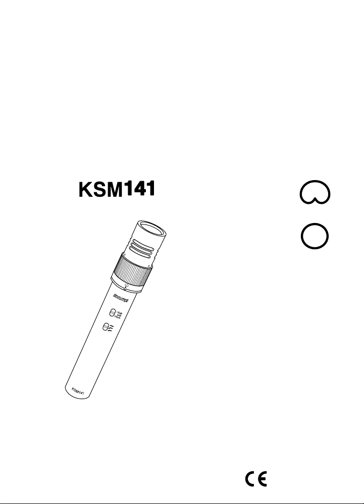
KSM141 DUAL POLAR PATTERN CONDENSER MICROPHONE
R
Thank you for selecting the KSM141
Over 75 years of audio experience has contributed to making the KSM141
one of the finest microphones available.
If you have any questions not answered in this booklet, please contact Shure
Applications Engineering at 847-866-2525, Monday through Friday, from 8:00 am to
4:30 pm, CST. In Europe, call 49-7131-72140. Our web address is www.shure.com.
Page 3
English
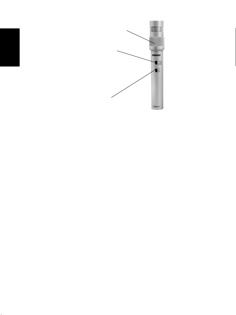
Rotating
Polar Pattern Switch
0/15/25 dB
Attenuation Switch
Low Frequency
Response Switch
FIGURE 1. KSM141
GENERAL DESCRIPTION
The Shure
mechanically switching dual polar patterns (cardioid and omnidirectional).
Designed for studio use, yet rugged enough for live applications, the KSM141 can
withstand extremely high sound pressure levels (SPL). Its low self-noise and
extended frequency response make it ideal for recording musical instruments.
R
KSM141 is an end-addressed condenser microphone with
FEATURES
SA mechanical polar pattern switch for highly consistent cardioid and true
omnidirectional polar patterns. Provides flexibility in a wide variety of recording
applications.
SUltra-thin, 2.5 µm, 24 karat gold-layered, low mass Mylar
superior transient response
SClass A, discrete, transformerless preamplifier for transparency, extremely
fast transient response, no crossover distortion, and minimal harmonic and
intermodulation distortion
SPremium electronic components, including gold-plated internal and external
connectors
SSubsonic filter eliminates low frequency rumble (less than 17 Hz) caused by
mechanical vibration
SThree-position switchable pad (0 dB, 15 dB, and 25 dB) for handling
extremely high sound pressure levels (SPLs)
SThree-position switchable low-frequency filter to reduce background noise
and counteract proximity effect
R
diaphragm for
2
Page 4
PERFORMANCE CHARACTERISTICS
SExtended frequency response
SLow self-noise
SExceptional reproduction of low-frequency sounds
SCan withstand high sound pressure levels (SPL)
SHigh output level
SNo crossover distortion
SUniform polar response
SSuperior common mode rejection and suppression of RFI (radio frequency
interference)
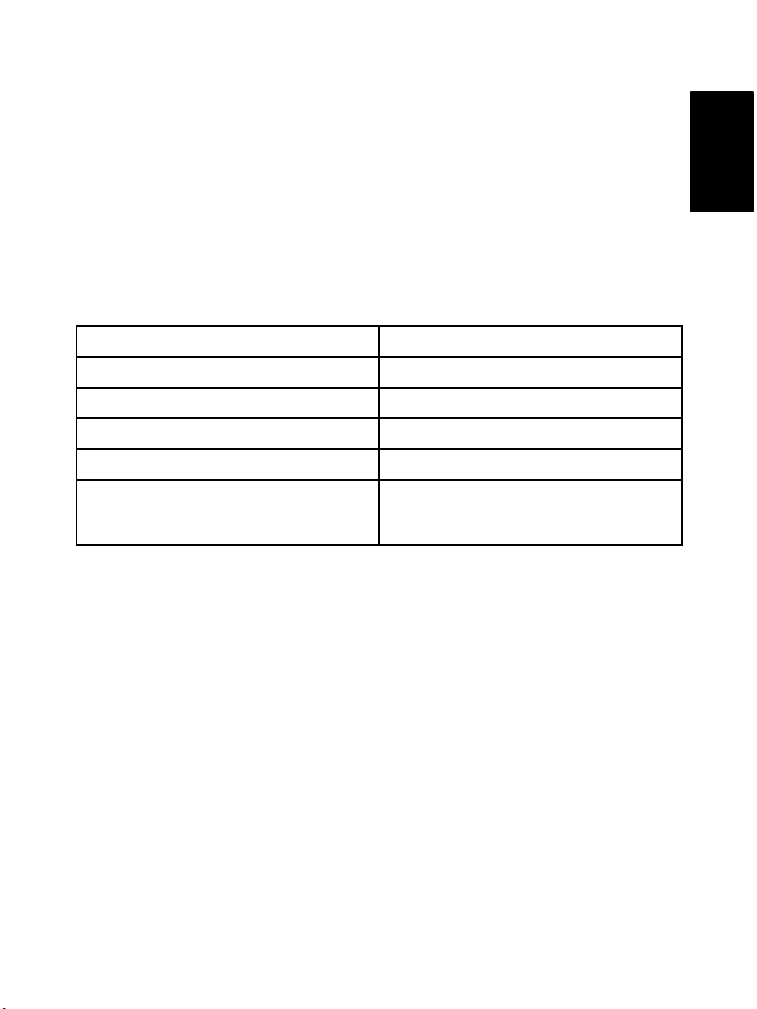
MODEL VARIATIONS
KSM141/SL KSM141/SL ST PAIR
One KSM141 Condenser Microphone Two KSM141 Condenser Microphones
One A141C Carrying Case One A141SPC Carrying Case
One A100WS Windscreen Two A100WS Windscreens
One A57F Stand Mount Two A57F Stand Mounts
One European-threaded adapter that
mates the A57F to European-threaded
microphone stands
Two European-threaded adapters that
mate the A57F to European-threaded
microphone stands
APPLICATIONS
The KSM141 produces superior results in any application requiring a high quality
microphone. Typical applications include:
SClose miking of acoustic instruments such as piano, guitar, violins, drums,
and percussion
SOverhead miking of drums and percussion instruments
SElectric guitar amplifiers
SBrass and woodwind instruments
SRoom ambience pick-up (guitar amplifier or drums)
SOrchestras, choirs, wind ensembles
SLow-frequency instruments such as double bass and kick drum
NOTE: Sound quality is strongly affected by microphone location and room
acoustics. To achieve the best overall sound for a particular application, it may be
necessary to experiment with microphone placement and various room treatments.
English
3
Page 5

USING THE KSM141
Mounting the Microphone
To secure the KSM141 to a floor stand or boom, thread the mount onto the
microphone stand and insert the microphone into the microphone clip.
Power Requirements
English
This microphone requires phantom power and performs best with a 48 Vdc supply
(IEC-268-15/DIN 45 596). It can operate on voltages as low as 11 Vdc, but headroom
and sensitivity will be decreased slightly.
NOTE: Most modern mixers provide phantom power.
Cable Connections
Use a cable with XLR connectors at each end.
Load Impedance
Shure recommends a load impedance of at least 1000 Ω. When used with modern
microphone preamplifiers rated at about 2500 Ω, the KSM141 provides higher
maximum SPL capability and output clipping level. When the attenuation switch is
set to the –25 dB position, it can handle up to 164 dB SPL, and can output +15 dBV
into a load of 5000 Ω or greater.
Selecting a Polar Pattern
To select either the cardioid or omnidirectional polar pattern, rotate the knurled ring
on the microphone in either direction until you feel a detent. The image of the
desired polar pattern should be directly above the notch at the base of the ring.
NOTE: Operating the KSM141 in a non-detent position (no polar pattern selected)
will produce an unpredictable polar pattern and may adversely affect frequency
response.
Cardioid. When this pattern is selected, the microphone picks up sounds
directly in front of the microphone and is least sensitive to those in back. This is the
most commonly used pattern in studio recording and live-sound applications. See
Figure 4.
Omnidirectional. Picks up sounds from all directions. This pattern is best for
picking up room ambience and for miking several sources, such as an ensemble
or multiple singers, simultaneously. The omnidirectional polar pattern exhibits no
proximity effect. See Figure 4.
WARNING: Rotating the polar pattern switch produces mechanical noise which,
when amplified, may damage the loudspeakers. Turn down any loudspeakers or
mute the microphone at the mixing console before changing the polar pattern.
4
Page 6

Setting Low-Frequency Response
Ñ
Ñ
Ñ
Ñ
Ñ
Ñ
Ñ
Ñ
s
A three-position switch on the microphone lets you adjust low frequency response.
The low frequency filters can be used to reduce wind noise, room noise, and
proximity effect. Refer to Figure 2.
Flat response. This setting provides
the most natural sound reproduction
in most applicatons.
Low-frequency cutoff. This setting
+5
0
dB
–10
provides an 18 dB-per-octave cutoff
at 80 Hz. It helps eliminate floor
rumble and low-frequency noise
produced by heating and air
conditioning systems. This setting
may also be used to compensate for
20 100050 100
Flat Response
Low-Frequency Cutoff
Low-Frequency Rolloff
Hz
98765432
proximity effect or to reduce low
frequencies that make an instrument
Figure 2. Low Frequency Response
sound dull or muddy.
Low-frequency rolloff. This setting provides a 6 dB-per-octave rolloff at 115 Hz.
Use this setting to compensate for proximity effect or to reduce low frequencies
that could make an instrument sound dull or muddy.
Setting Attenuation
The attenuation switch lets you reduce the signal level by up to 25 dB without
altering frequency response. This can prevent extremely loud sounds from
overloading the microphone. Set the switch to the desired attenuation levels as
follows:
0 dB – Move the switch to this position for “quiet” to “normal” sound levels.
-15 dB – Move the switch to this position when the microphone is approximately 0.75 meters (2 feet) from sound sources such as a kick drum, snare
drum, or electric guitar cabinet.
-25 dB – Move the switch to this position when the microphone is 4 inches
(10 cm) or less from extremely loud sound sources such as kick drum, snare
drum, or guitar cabinets.
English
5
Page 7

SPECIFICATIONS
Cartridge Type Permanently Biased Condenser
Frequency Response 20–20,000 Hz (see Figures 3 and 5)
Directional Polar Pattern Cardioid/Omnidirectional (see Figures 4 and 6)
English
*20 Hz to 20 kHz; THD < 1%. THD of the microphone preamplifier when applied input signal is equivalent to the cartridge
**S/N ratio is difference between 94 dB SPL and equivalent SPL of self-noise A-weighted.
Output Impedance 150 Ω (actual)
Attenuation Switch 0 dB,15 dB, or 25 dB attenuation
Low Frequency Response Switch Flat; –6 db/octave below 115 Hz;
Phantom Power 48 Vdc± 4 Vdc (IEC–268–15/DIN 45 596), positive
Current Drain 4.65 mA typical at 48 Vdc
Common Mode Rejection ≥ 50 dB, 20 Hz to 20 kHz
Polarity Positive pressure on diaphragm produces positive
Dimensions and Weight 20 mm (0.8 in.) diameter, 146 mm (5.75 in.) long;
Sensitivity (typical, at 1000 Hz;
1 Pa = 94 dB SPL)
Self–noise (typical, equivalent SPL;
A-weighted, IEC 651)
Maximum SPL
5000 load (Attenuator on)
2500 load (Attenuator on)
1000 load (Attenuator on)
Output Clipping Level*
5000 load
2500 load
1000 load
Dynamic Range
5000 load
2500 load
1000 load
Signal to Noise Ratio** 80 dB
output at specified SPL.
–18 dB/octave below 80 Hz
pins 2 and 3
voltage on output pin 2 relative to pin 3
156 grams (5.5 oz.) (see Figure 7)
–37 dBV/Pa
14 dB
145 (160, 170) dB
139 (154, 164) dB
134 (149, 159) dB
15 dBV
9 dBV
3 dBV
131 dB
125 dB
120 dB
6
Page 8

CARDIOID RESPONSE GRAPHS
60 cm
FIGURE 3. TYPICAL CARDIOID FREQUENCY RESPONSE
English
250 Hz
500 Hz
1000 Hz
2500 Hz
6400 Hz
10000 Hz
FIGURE 4. TYPICAL CARDIOID POLAR PATTERNS
7
Page 9

OMNIDIRECTIONAL RESPONSE GRAPHS
English
60 cm
FIGURE 5. TYPICAL OMNIDIRECTIONAL FREQUENCY RESPONSE
250
500
1K
2500
6400
10K
FIGURE 6. TYPICAL OMNIDIRECTIONAL POLAR PATTERNS
20 mm
(0.8 IN)
146 mm
(5.75 IN)
FIGURE 7. DIMENSIONS
8
Page 10

CERTIFICATION
Eligible to bear CE Marking; Conforms to European EMC directive 89/336/EEC.
Meets applicable tests and performance criteria found in European Professional
Audio Products EMC Standard EN 55103 (1996); Part 1 (Emissions) and Part 2
(Immunity). The KSM141 is intended for use in environments E1 (residential) and
E2 (Light Industrial) as defined in European standard EN 55103. EMC conformance
is based on the use of shielded interconnecting cable.
FURNISHED ACCESSORIES
Case A141C. . . . . . . . . . . . . . . . . . . . . . . . . . . . . . . . . . . . . . . . . . . . . . . . . . . . . . .
Case (Stereo Pair) A141SPC. . . . . . . . . . . . . . . . . . . . . . . . . . . . . . . . . . . . . . . .
Windscreen A100WS. . . . . . . . . . . . . . . . . . . . . . . . . . . . . . . . . . . . . . . . . . . . . . .
Microphone Clip A57F. . . . . . . . . . . . . . . . . . . . . . . . . . . . . . . . . . . . . . . . . . . . . .
OPTIONAL ACCESSORIES
SHOCKSTOPPERt Shock Mount A53M. . . . . . . . . . . . . . . . . . . . . . . . . . . . . .
SERVICE
For additional microphone service or parts information, please contact the Shure
Service Department at 1-800-516-2525. Outside the United States, please contact
your Authorized Shure Service Center.
English
9
Page 11

Trademark Notices: The circular S logo, the stylized Shure logo, and the word
“Shure” are registered trademarks of Shure Incorporated in the United States.
“SHOCKSTOPPER” is a trademark of Shure Incorporated in the United States.
“Mylar” is a registered trademark of E.I. duPont de Nemours and Company in the
United States. These marks may be registered in other jurisdictions.
 Loading...