

Page 1
Shure
Main Menu
Brothers Incorporated
222 Hartrey A
Evanston IL 60202-3696 U.S.A.
venue
Model DFR1
1EQ V
ersion 4 User Guide
DFR11EQ
Digital Feedback Reducer
with Windows Software Version 4 for Equalizer and Delay
avec logiciel Windows version 4 pour égaliseur et délai
mit Windows Softwareversion 4 für Equalizer und Delay
Reductor digital de realimentación y ecualizador gráfico
con software Versión 4 compatible con Windows
con software Windows, versione 4, per equalizzatore
*
Réducteur de Larsen numérique
*
Digitale Rückkopplungsreduzier–Stufe
*
para ecualizador y retardo
Attenuatore di retroazione digitale
*
*
1997, Shure Brothers Inc.
27A8595 (QG)
e ritardo
Printed in U.S.A.
Page 2

TABLE OF CONTENTS
Main Menu
WHAT’S
INTRODUCTION 3
THE
VERSION
FEEDBACK
EQUALIZER 19
DELAY 25
OUTPUT
NEW IN VERSION 4 SOFTW
. . . . . . . . . . . . . . . . . . . . . . . . . . . . . . . . . . . . . . . . . . . . . . . . . . . . . . . . . . . . . . . . . . . . . . . . . . . . . . . . .
Features 3
Added
DFR1
Overview 4
DFR11EQ Theory 6.
Setup
Audio
Introduction 12
Overview 15
Graphic
Parametric
. . . . . . . . . . . . . . . . . . . . . . . . . . . . . . . . . . . . . . . . . . . . . . . . . . . . . . . . . . . . . . . . . . . . . . . . . . . . . . . . . . . . . . . . .
IN/OUT
Reversing
. . . . . . . . . . . . . . . . . . . . . . . . . . . . . . . . . . . . . . . . . . . . . . . . . . . . . . . . . . . . . . . . . . . . . . . . . . . . . . . . . . . .
Features When Interfaced with a Personal Computer3. . . . . . . . . . . . . . . . . . . . . . . . . . . . . . . . . . . . . . .
1EQ 4.
. . . . . . . . . . . . . . . . . . . . . . . . . . . . . . . . . . . . . . . . . . . . . . . . . . . . . . . . . . . . . . . . . . . . . . . . . . . . . . . . . .
. . . . . . . . . . . . . . . . . . . . . . . . . . . . . . . . . . . . . . . . . . . . . . . . . . . . . . . . . . . . . . . . . . . . . . . . . . . . . . . . . . . .
. . . . . . . . . . . . . . . . . . . . . . . . . . . . . . . . . . . . . . . . . . . . . . . . . . . . . . . . . . . . . . . . . . . . . . . . . . .
for Feedback Control8. . . . . . . . . . . . . . . . . . . . . . . . . . . . . . . . . . . . . . . . . . . . . . . . . . . . . . . . . . . . . . . . . . . .
Connections
4 SOFTW
. . . . . . . . . . . . . . . . . . . . . . . . . . . . . . . . . . . . . . . . . . . . . . . . . . . . . . . . . . . . . . . . . . . . . . . . . . . . . . . . .
. . . . . . . . . . . . . . . . . . . . . . . . . . . . . . . . . . . . . . . . . . . . . . . . . . . . . . . . . . . . . . . . . . . . . . . . . . . . . . . . . . .
REDUCER
. . . . . . . . . . . . . . . . . . . . . . . . . . . . . . . . . . . . . . . . . . . . . . . . . . . . . . . . . . . . . . . . . . . . . . . . . . . . . . . . . . . .
Equalizer
Equalizer
CONTROLS
Meters and Output Control
the Signal Polarity
. . . . . . . . . . . . . . . . . . . . . . . . . . . . . . . . . . . . . . . . . . . . . . . . . . . . . . . . . . . . . . . . . . . . . . . . .
ARE 12.
. . . . . . . . . . . . . . . . . . . . . . . . . . . . . . . . . . . . . . . . . . . . . . . . . . . . . . . . . . . . . . . . . . . . . . . .
. . . . . . . . . . . . . . . . . . . . . . . . . . . . . . . . . . . . . . . . . . . . . . . . . . . . . . . . . . . . . . . . . . . . . . . . .
. . . . . . . . . . . . . . . . . . . . . . . . . . . . . . . . . . . . . . . . . . . . . . . . . . . . . . . . . . . . . . . . . . . . . . . . . .
. . . . . . . . . . . . . . . . . . . . . . . . . . . . . . . . . . . . . . . . . . . . . . . . . . . . . . . . . . . . . . . . . . . . . . . .
. . . . . . . . . . . . . . . . . . . . . . . . . . . . . . . . . . . . . . . . . . . . . . . . . . . . . . . . . . . . . . . . . . . . . . . . . .
ARE 2.
. . . . . . . . . . . . . . . . . . . . . . . . . . . . . . . . . . . . . . . . . . . . . . . . . . . . . . . . .
10.
16.
19.
22.
28.
. . . . . . . . . . . . . . . . . . . . . . . . . . . . . . . . . . . . . . . . . . . . . . . . . . . . . . . . . . .
. . . . . . . . . . . . . . . . . . . . . . . . . . . . . . . . . . . . . . . . . . . . . . . . . . . . . . . . . . . . . . . . .
28.
28.
RESPONSE
Response
Snapshots 30
SHURE
MAINTENANCE 32
Scenes 32
Customizing
Exiting
Printing
APPENDIX
APPENDIX
APPENDIX
APPENDIX
GRAPH
Curves
. . . . . . . . . . . . . . . . . . . . . . . . . . . . . . . . . . . . . . . . . . . . . . . . . . . . . . . . . . . . . . . . . . . . . . . . . . . . . . . . . .
LINK NETWORKS
. . . . . . . . . . . . . . . . . . . . . . . . . . . . . . . . . . . . . . . . . . . . . . . . . . . . . . . . . . . . . . . . . . . . . . . . . . . . . . . . . . . . .
the DFR1
DFR1
A. SPECIFICA
B. RACK MOUNTING THE DFR1
C. CONNECT
D. KEYBOARD CONTROLS
Trademark
registered trademark of Microsoft Corporation. Crystal is a trademark of Crystal Semiconductor
Corporation.
the
IBM Corporation.
. . . . . . . . . . . . . . . . . . . . . . . . . . . . . . . . . . . . . . . . . . . . . . . . . . . . . . . . . . . . . . . . . . . . . . . . . . .
. . . . . . . . . . . . . . . . . . . . . . . . . . . . . . . . . . . . . . . . . . . . . . . . . . . . . . . . . . . . . . . . . . . . . . . . . .
. . . . . . . . . . . . . . . . . . . . . . . . . . . . . . . . . . . . . . . . . . . . . . . . . . . . . . . . . . . . . . . . . . . . . .
. . . . . . . . . . . . . . . . . . . . . . . . . . . . . . . . . . . . . . . . . . . . . . . . . . . . . . . . . . . . . . . . . . . . . . . . . . . . . . . .
Graph Colors
1EQ Application
1EQ Settings
Motorola is a registered trademark of Motorola, Inc. IBM is a registered trademark of
. . . . . . . . . . . . . . . . . . . . . . . . . . . . . . . . . . . . . . . . . . . . . . . . . . . . . . . . . . . . . . . . . . .
. . . . . . . . . . . . . . . . . . . . . . . . . . . . . . . . . . . . . . . . . . . . . . . . . . . . . . . . . . . . .
. . . . . . . . . . . . . . . . . . . . . . . . . . . . . . . . . . . . . . . . . . . . . . . . . . . . . . . . . . . . . . . . . .
TIONS 35.
ORS AND CABLES
Notifications:
. . . . . . . . . . . . . . . . . . . . . . . . . . . . . . . . . . . . . . . . . . . . . . . . . . . . . . . . . . . . . . . .
1EQ 37.
. . . . . . . . . . . . . . . . . . . . . . . . . . . . . . . . . . . . . . . . . . . . . . . . . . . . . . . . . .
Shure is a registered
. . . . . . . . . . . . . . . . . . . . . . . . . . . . . . . . . . . . . . . . . . . . . . . . .
. . . . . . . . . . . . . . . . . . . . . . . . . . . . . . . . . . . . . . . . . . . . . . . . . . . . .
trademark of Shure Brothers, Inc. Windows is a
29.
29.
31.
33.
33.
34.
38.
42.
1
Page 3

WHAT’S NEW IN VERSION 4 SOFTWARE...
Main Menu
Software
V
ersion 4 for the DFR1
1EQ of
fers the same features as before,
plus much more...
Switchable Graphic or Parametric Equalization...
graphic
situations arise. Use the graphic equalizer to equalize overall room sound; or use the parametric
equalizer
up
Editable Digital Feedback Filters...
feedback
Digital
in fill systems. The delay can improve the audio quality of a sound system by delaying the audio
signal to the remote loudspeaker until it is in alignment with the sound waves coming from other
loudspeakers
More Scenes...
DFR11EQ.INI
separate
Scene
equalizer or as a parametric equalizer
to control the major feedback frequencies covered by the feedback filters, so you can free
all the feedback filters to act as dynamic filters for stray feedback.
filters, so the feedback filters can be utilized as additional parametric filters.
Delay
...
For use in larger sound systems which utilize widely spaced loudspeakers, such
in front. Phase cancellation and sound localization problems are minimized.
Unlike the Version 3 software, which is limited to 16 scenes stored in the
file on the computer
files. There is now a field for entering descriptions of scenes which appears in the Recall
function, so you can find the desired scene before loading.
, the V
. This flexibility can help
You can edit the frequency, depth, and width of individual
ersion 4 software can
Hold Mode Automatically Restores the Basic Feedback Filter Setup...
room, just flip the Update/Hold DIP switch to the Hold position. In Hold mode, a DFR11EQ may
change
you power up the unit. This is useful for storing the best filter settings for a given system — that
system can then be set in Update mode for a different program, then returned to Hold mode to
restore
Dynamic filters or deepen Fixed filters, but the original settings will be restored the next time
the usual settings.
Now, you can set the equalizer to work as a
meet your needs as dif
store any number of scenes each in
Once you ring out a
ferent
as
Reverse
inverts the polarity of the audio signal, use the Version 4 software to provide the correct signal
polarity.
DFR11EQ
you
Input
you
see
There
response
Undo...
Response Graph Snapshots...
response
see
Advanced
ID,
Device
Window
can
you
hide the Response Graph to leave room on the screen to view other applications you may be
running.
the Output Signal Polarity
Setting Printouts...
can now printout a hardcopy which shows all of the settings for a selected DFR1
and Output Level Meters and Output Control...
can see the ef
if the equalized output sound levels are getting too low compared
is now a output control you can use to raise the output level to compensate.
curve graph will adjust with the
It is now possible to undo the most immediate filter deletions.
curve.
the dif
ference between the old response and the new
fect of the signal processing on the audio signal. Y
As you make changes in the filters or equalization, you can show the snapshot to
Shure Link Networking Options...
to make it easier to remember the Devices in a system. The new networking menu identifies the
ID, name, scene, modified status of that scene, and Device type.
Hiding...
now independently hide the Equalizer panel and the Response Graph panel. For instance, if
want to set the graphic equalizer
If you want to use the software but need to conserve space on the screen, you
...
If there is a piece of equipment in the sound system which
These are useful for documenting a sound system.
There are now input and output meters, so
ou can check these meters to
to the unaf
output level slider
When you take a snapshot, the computer stores the frequency
Y
ou can assign an individual name to each Device
, but have no current need
, showing you the current operating level.
.
to see the Response Graph, you can
With this option,
1EQ.
fected input levels.
The frequency
Backwards
Upgradeability
...
Using software V
ersion 4, earlier DFR1
2
1EQs can be upgraded.
Page 4
INTRODUCTION
Main Menu
The Shure Model DFR11EQ is a single channel signal processor that combines a feedback
reducer,
in a sound reinforcement signal path to automatically detect and control acoustical feedback and
equalize overall sound system response. The DFR11EQ is designed for installed sound
reinforcement
DFR11EQ is also an effective setup tool for controlling major feedback modes in live music
applications.
feedback frequencies. These notch filters stop a sound system from feeding back, but are narrow
enough so their effect on audio quality is minimized. The feedback detection algorithm constantly
searches for feedback, with or without the presence of program audio. The feedback reducer
functions
equalizer
The feedback reducer of the DFR11EQ automatically inserts narrow notch filters at detected
on its own or under external computer control.
The equalizer of the DFR1
, and delay in a single, half-rack enclosure. The DFR1
applications: theater
1EQ is designed
, conference
1EQ can be set to act as either a graphic or parametric equalizer
rooms, meeting halls, houses of worship, etc. The
to be placed
.
Hardware
Adaptive
which automatically detects feedback and deploys
up to 10 narrow band notch filters.
Crystal* 20-bit A/D and D/A converters
(Analog-to-Digital, Digital-to-Analog) for 104 dB
dynamic range.
48 kHz sampling rate for flat response to 20 kHz.
1
/
2
one or two units in a single rack space with no
sagging or bending.
Shure Link Interface allows multiple units to be
programmed with a single computer
No internal batteries. Settings and DSP program
stored in internal EEPROM.
Electronically balanced input with combination
1
/
4
balanced or unbalanced outputs.
Software
A tamper
between 30–band graphic or 10–band parametric.
The graphic equalizer is constant-Q, 30-band,
1
/
3
dB or cut 12 dB for each band.
The parametric equalizer offers 10 filters with
adjustable frequency, up to 6 dB of boost or –18
dB of cut, and up to a two octave bandwidth.
Features
Notch Filter algorithm (patent pending)
rack space chassis allows rack mounting of
.
-in. and XLR connector
. Can be used with
Features
-proof equalizer which can be switched
-octave graphic equalizer.
Can boost up to 6
Independently driven, cross-coupled, balanced
1
/
-in. and XLR outputs. Can be used with
4
balanced or unbalanced inputs, without signal
loss.
+4 dBu/–10 dBV DIP-switch-selectable input and
output levels.
80 MHz Motorola* DSP56009 processor engine
with full 24-bit internal processing.
RS-232 interface for external computer control
and firmware updates.
Internal linear power supply switchable between
120 and 240 V
cumbersome external power supply
Solid state bypass eliminates unreliable
mechanical relays and switches.
Up to 100 ms Digital Delay
Front/back panel lockout control.
Response Curve V
response of the feedback reducer
both.
Storage of multiple scenes to floppy or hard disk.
ac eliminates the need for a
.
.
iewing. Displays frequency
, equalizer
, or
3
Page 5
THE DFR11EQ
Main Menu
Overview
Front Panel
BYPASS Button and LED. Press this button to
suspend
filters from the audio path. Does not affect the
graphic
feedback
feedback reducer operation and remove
equalizer. When the LED illuminates, the
reducer is bypassed.
SIGNAL LED. Illuminates when input signal is
present.
Intensity varies with input signal level.
CLIP LED. Illuminates when the input signal is
6 dB of clipping.
within
CLEAR Filters Button and LED. Press this
recessed button to reset all the feedback filters.
filters even if Lock Filters is enabled. LED
Clears
illuminates
Back Panel
as the button is pressed.
LOCK
Filters Button and LED.
to
lock the filters at their current values. When the
LED is on, the unit will not change or add any
feedback
filters.
Press this button
FILTERS LEDs (10). Indicate when individual
feedback
or
is added, the LED flashes, then stays on.
filters are active. When a filter changes
NEW LED. Flashes in unison with the feedback
filter LEDs when the detector is deploying a new
feedback filter or changing an existing one. Also
flickers
from
whenever the unit is receiving commands
a connected computer
.
POWER Switch and LED. Press this button to
turn the power on. LED illuminates when unit is
powered on. When the power is off, the unit is
bypassed
automatically.
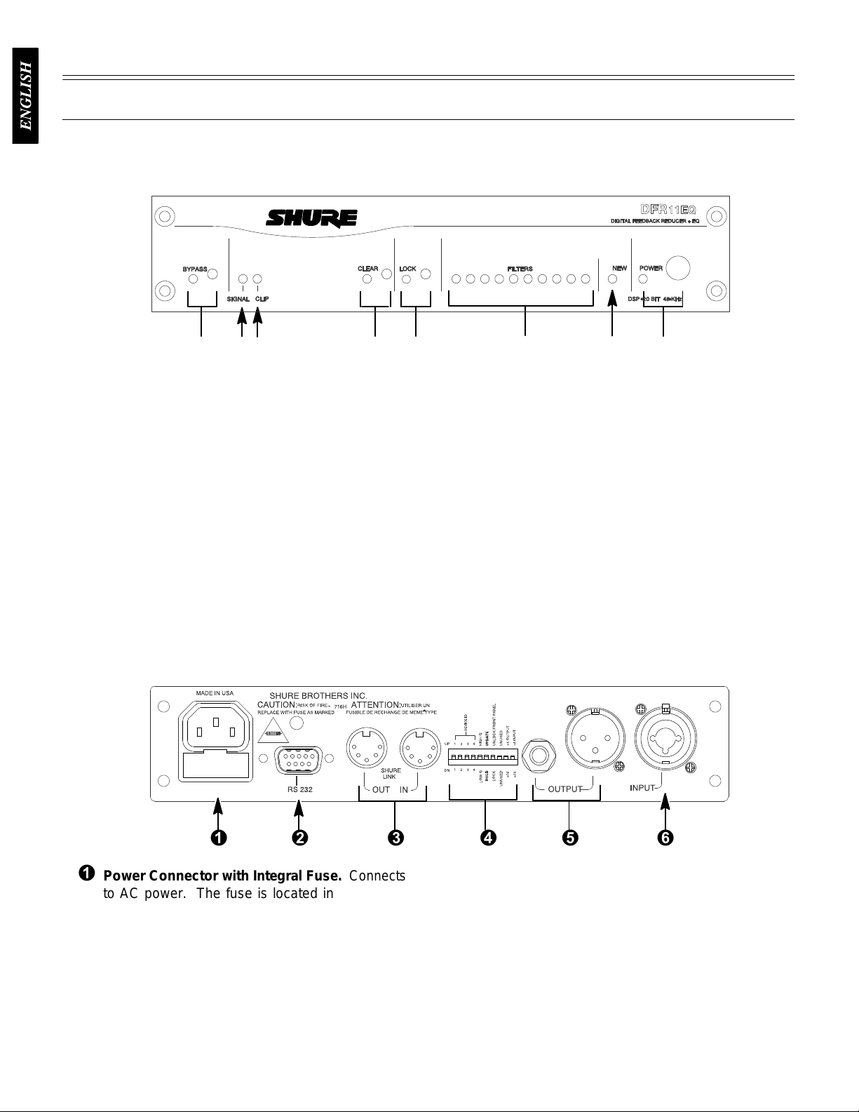
Power
to AC power. The fuse is located in the drawer
below
9-Pin RS-232 Port. Connects the unit to a
computer. For use with DFR11EQ software and
for
Shure Link Interface. Allows linking of up to 16
DFR11EQs
DIP
Output Connector—
Connector
the connector.
DSP firmware upgrades.
which may be accessed by computer
Switches.
with Integral Fuse.
See
DIP Switches
1
/4-Inch & XLR. Active,
Connects
.
cross-coupled,
balanced
between +4 dBu/–10 dBV line-level operation by
DIP switch.
independently and either can be balanced or
unbalanced
balanced outputs can be used with
or unbalanced inputs.
1
/4-Inch and XLR are driven
without af
fecting the other
Can be switched
.
Input Connector—Combined XLR and
1
/4-Inch.
.
4
balanced
between +4 dBu/–10 dBV line-level operation by
DIP
Active balanced input can be used with
or unbalanced outputs. Can be switched
switch.
Page 6
DIP
Main Menu
Switches
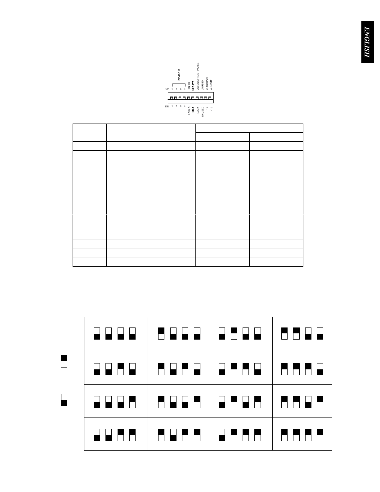
The
DIP switches located on the rear panel are used for adapting the unit to the sound system
requirements.
DIP
SWITCH
1–4
5
6
7
8 unused — —
9
10
Switches 5 through 10 change other available options, see the table below
FUNCTION POSITION
UP DOWN
Device ID see below see below
Feedback Filter Bandwidth Select
Determines
Feedback Filter Memory Mode
Front Panel Lockout
Disables the front panel controls,
except the power switch. Protects
current settings from tampering.
Output Sensitivity
Input Sensitivity
the Q of the feedback
filter
.
High
Q
1/10-octave
Feedback Filters re
main narrow as they
deepens
Update
Stores changed
feedback
filter settings
on
power down
Unlock
Front panel buttons
operational
+4 dBu
+4 dBu
1/10-octave
widenFeedback
widen
as they deepen
Discards changed
feedback
on
power down, but
holds original
settings
Front panel buttons
inactive
–10 dBV
–10 dBV
Low Q
Filters
Hold
filter settings
Lock
.
Shure Link Device ID
When multiple DFR11EQ’s are linked, each one musty be assigned a unique Device ID, 0
through
Device
Device
SWITCH UP
SWITCH DOWN
15. DIP switches 1 through 4 on the rear panel are used to set the Device ID. T
ID,
align the switches according to the illustrations below
ID 15.
DEVICE
123
DEVICE ID 4
123
DEVICE ID 8
123
DEVICE ID 12
123
ID 0
4
4
4
4
DEVICE ID 1
123
DEVICE ID 5
123
DEVICE ID 9
123
DEVICE ID 13
123
4
4
4
4
. The unit comes factory preset to
DEVICE ID 2
123
DEVICE ID 6
123
DEVICE ID 10
123
DEVICE ID 14
123
4
4
4
4
DEVICE ID 3
123
DEVICE ID 7
123
DEVICE ID 1
123
DEVICE ID 15
123
o change the
4
4
1
4
4
5
Page 7
DFR11EQ Theory
Main Menu
Feedback
high. Since no sound system (microphones, loudspeakers, room acoustics, etc.) has an absolutely
flat frequency response, feedback will occur at specific frequencies before others; these are the
frequencies with the most gain. If the gain at only these specific frequencies is lowered, then the
system can operate with more overall gain before it feeds back, without a perceptible difference in
tonal
discriminate
detects
gain
in
3 dB increments (up to –18 dB) until the feedback stops.
the
and
installed
and DFR1
When
acoustical feedback occurs in a sound system, it
quality
At the heart of the DFR11EQ is a very powerful algorithm that can accurately and quickly
feedback, it smoothly inserts a –3 dB, 1/10-octave notch filter into the audio path to reduce the
at the frequency which is feeding back. If the feedback does not stop, the filter depth is increased
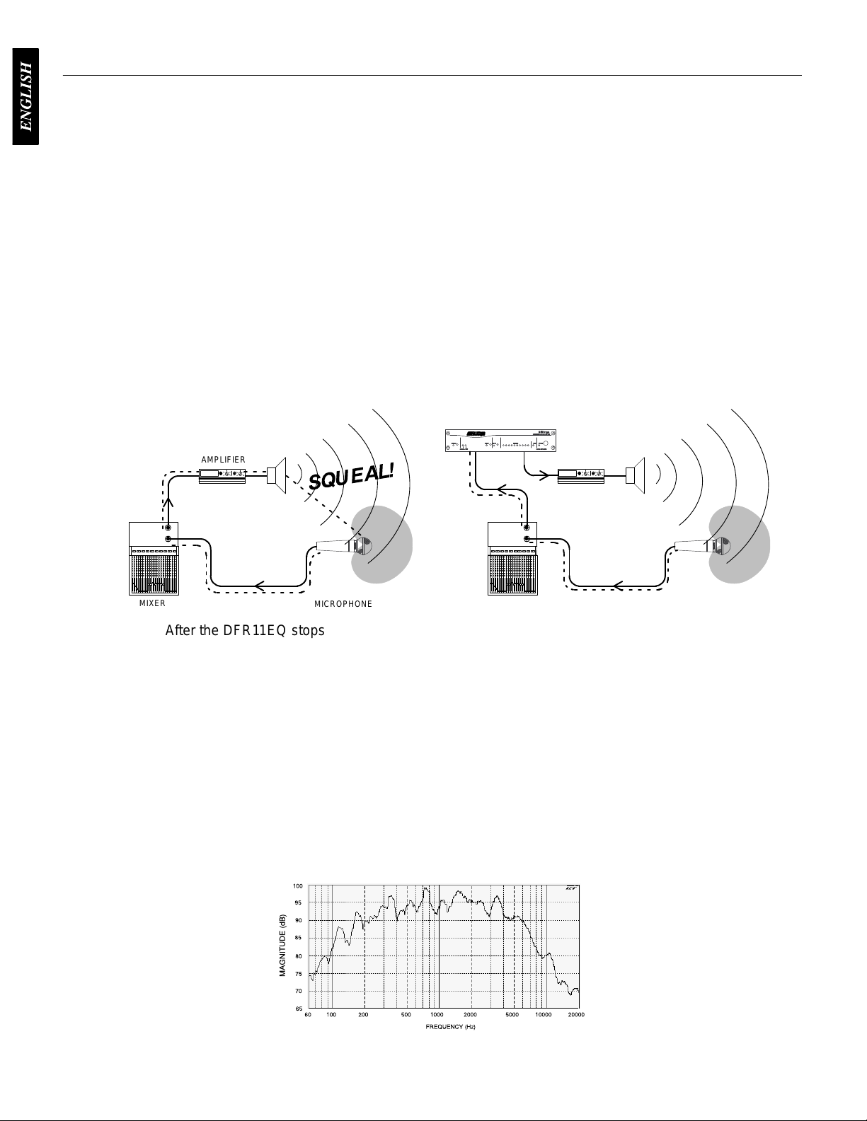
The
illustrations below demonstrate how
left shows a feedback loop, where the microphone picks up of
sends it back
in the sound system, senses that loop and filters out the excess gain on that frequency
AMPLIFIER
1EQ Operation
is because the gain of the system is too
. This is the operating principle of the DFR1
between feedback and non-feedback
the DFR11EQ works in a sound system. The system on
into the sound system. The system on the right shows how the DFR1
1EQ.
sounds (speech and music). When this algorithm
f axis sound from the loudspeaker
DFR11EQ
AMPLIFIER
1EQ, when
.
MIXER
After the DFR11EQ stops the feedback at one frequency, the sound system may start feeding
back
at another frequency
at
the new frequency
DFR11EQ Limitations
The
DFR1
1EQ (or any other notch filter system) cannot entirely eliminate feedback in a sound
system,
4 to 8 notch filters are set. This is because generally there are only a few dominant frequency
response
very well controlling these peaks. The user can expect a 6 to 9 dB improvement of
gain-before-feedback
of the frequencies have too much gain; instead of trying to notch out all of the frequencies, better
results
other changes must be made to the sound system such as different microphone or loudspeaker
placement.
it can only help to reduce it. In a typical system, a point of diminishing returns is reached after
peaks above the response of the entire system (see diagram
will be obtained by lowering the gain of the system. If the system still has insuf
MICROPHONE
. In this case, the DFR1
. The DFR1
in a typical system. However
1EQ can insert a total of 10 notch filters to reduce feedback.
MIXER
1EQ inserts another notch filter into
below). The DFR1
, if the system has too much overall gain, then all
MICROPHONE
the audio path
1EQ works
ficient gain, then
FREQUENCY
RESPONSE OF AN UNEQUALIZED SOUND SYSTEM
6
Page 8
Fixed and Dynamic Notch Filters
Main Menu
The
DFR1
1EQ can
filters
are factory preset as 5 fixed and 5 dynamic filters. The first filters to be set are fixed, then the
remaining
detected, the DFR1
frequency.
as an existing dynamic or fixed filter, the existing filter will deepen. The number of fixed versus
dynamic
that has fixed microphone and loudspeaker locations. In this type of system, the most dominant
frequencies
placement, and will not change appreciably. However, feedback can still occur, for instance, when
someone’s
fixed
frequencies
several
this
experimentation
filters are set as dynamic. After all 10 notch filters are set and a new feedback frequency is
The fixed filters remain unchanged. However
filters can be adjusted via the DFR1
An
example of a system that would benefit from more fixed filters and fewer dynamic filters is one
of feedback are defined
hand or head approaches a microphone. A good setting for this type of system would be 7
filters for the non-changing feedback frequencies, and
caused by the talker
On the other hand, more dynamic than fixed filters would be appropriate in a system that has
non-stationary wireless microphones. Eight or even all 10 filters could be set to dynamic in
type of system to obtain maximum feedback protection. As every application is dif
control the notch filters as either
1EQ will remove the oldest set dynamic filter and re-deploy it at the new feedback
by the room dimensions and the microphone and loudspeaker
.
is recommended to get the best results from a given sound system.
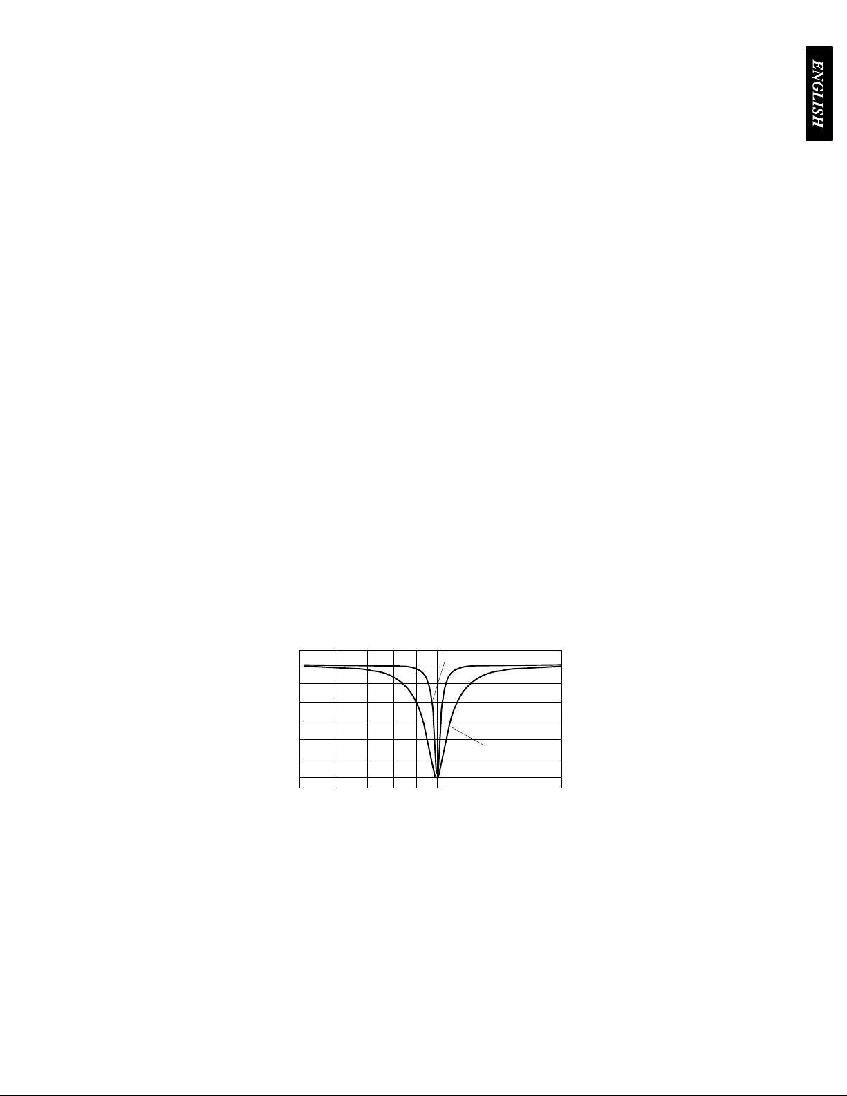
High Q Filters vs. Low Q Filters
The
DFR1
1EQ of
Q,
is the default setting. A High Q filter’s width stays very narrow as the filter depth is increased. This
attenuates the minimum amount of signal possible to ensure system stability, while maintaining
excellent
effectively
greater system stability than the High Q setting, but with slightly diminished sound quality. This
setting
the
sound quality
The Low Q setting maintains the filter’s shape as it is deepened, so the width of the filter
widens as the depth increases. Using this setting attenuates the signal more, producing a
is appropriate for systems such as a speech-only P
sound quality can be compromised a bit.
fers two selections for the shape of the 1/10-octave notch filters. The first, High
. This setting is appropriate for most applications.
dynamic
, if feedback occurs at the same frequency
1EQ’
s Windows interface.
A where stability is an absolute must, but
HIGH
Q
or
fixed.
The DFR1
3 dynamic filters to catch the feedback
1EQ’
s 10 notch
ferent, some
Filter Locking
LOW Q
The
feedback filters
When locked, new filters will not be deployed and existing filters will not be deepened, even if
feedback is detected. The DFR11EQ’s algorithm is designed to accurately differentiate feedback
from
non-feedback sounds such as speech. However, certain sounds which sound like feedback,
such
as high notes on a piano or synthesizer
You
may want to lock the feedback filters during a musical performance for artistic
guitar
players
removing
For most applications, locking the feedback filters is unnecessary. As a rule of thumb, if the
application
the
filters after ringing out the sound system.
like to play with feedback as part of their sound, so locking the filters keeps them from
any desired feedback.
will contain material which sounds similar to acoustic feedback, then it is
can be locked from the front panel of the unit or from the computer interface.
, may cause the algorithm to deploy an unwanted filter
reasons—many
prudent to lock
7
.
Page 9

Setup for Feedback Control
Main Menu
The
DFR1
1EQ will operate stand-alone as a feedback reducer
personal
Computer Interface
“Insurance Policy” method. Each is valid for different situations. The “Ring Out” method is a
preemptive measure in which the system gain is raised beyond the normal setting to deliberately
make the system feed back. The DFR11EQ will then set its filters, and the system gain is then
reduced slightly, and the system is stable and useable. This set-up method is primarily used for
systems
filters
not
for systems which already have sufficient gain-before-feedback, but need protection from the
occasional stray feedback which can occur due to non-stationary microphones or user-adjustable
gain
Setup
computer running the supplied DFR1
for details.
There are two basic ways in which to set-up the DFR11EQ: The “Ring Out” method and the
which are operated near the feedback point and need an extra margin of stability
For the “Insurance Policy” method, the DFR11EQ is simply installed in the sound system, but
are not set prior to use.
expected to feed back, but if it does, the DFR11EQ is there to catch it. This set-up method is used
controls.
1.
Connect the DFR1
2.
Set the input and output level DIP switches to the appropriate settings for the sensitivities
of the connected equipment.
The DFR1
1EQ in the desired signal path location. See
1EQ adds extra insurance against feedback: the system is
. However
1EQ software, additional options are available. See
, when connected to a
.
Audio Connections.
WARNING:
power of
recommended that you avoid using this setting.
3.
Set the system gain to minimum, and power up all of the equipment.
4.
Slowly raise the gain of the system, and set the gain of each microphone to achieve the
desired level.
5.
The red CLIP LED should illuminate only on the highest signal peaks. If it illuminates
more frequently
level of the signal going into the DFR1
6.
At this point it is highly recommended to equalize the sound system with the DFR1
built–in equalizer (see
feedback reducer is more ef
Other equipment may potentially be damaged after DFR1
f if the DFR1
1EQ input is set to +4 and the output is set to –10. It is
, check to see that the input level switch is set properly. If it is, lower the
1EQ.
Computer Interface
fective on a well–equalized sound system.
) or an external equalizer
Ringing Out the System (“Ring Out” method only)
1. If
necessary, clear any notch filters in the DFR1
of
f the BYP
2.
Slowly raise the gain of the signal going through the DFR1
the DFR1
3.
Repeat step 2 until all fixed filters are set. (There are 5 fixed filters, unless changed by
the user via the computer interface.)
4.
Lower the gain by 3 to 6 dB to stabilize the sound system.
ASS and LOCK LEDs if they are not already of
1EQ will insert a filter deep enough to stop the feedback.
1EQ by pressing the CLEAR button. T
1EQ
1EQ’s
. The DFR1
f.
1EQ. When feedback occurs,
1EQ’s
urn
8
Page 10

Hold/Update
Main Menu
UPDATE
the
DFR1
powered on again, the feedback filters will be at exactly the same settings as when the unit was
powered
HOLD
DFR11EQ immediately saves the feedback filters at the current settings. When the DFR11EQ is
powered off, any changes made to the feedback filters after the switch was set will be forgotten.
When powered on again, the feedback filter settings will be exactly the same as when the
HOLD/UPDATE
best
filter settings for a sound system.
T
o store filter settings in the HOLD memory:
1.
2.
3.
4.
5.
position...
1EQ saves the feedback filters every time the unit is powered of
down.
position...
DIP switch was changed to the HOLD
Set the Hold/Update DIP switch to the Update position;
Ring out the room until all fixed filters are set;
Set the Hold/Update DIP switch to the Hold position;
During the performance, the DFR1
ones;
After the performance, turn the power of
state they were in before the performance.
When the HOLD/UPDA
When the HOLD/UPDA
1EQ will change dynamic filters and deepen fixed
TE DIP switch is
TE DIP switch is changed to the HOLD position, the
position. This feature is useful for storing the
f and back on; the DFR filters are restored to the
in the UPDA
TE position (default),
f. When the DFR1
1EQ is
9
Page 11
Audio Connections
Ñ
Ñ
Ñ
ССССССССССССС
Ñ
Ñ
Ñ
Ñ
Ñ
Main Menu
The
DFR1
1EQ should be placed where an equalizer would be in a signal path — it should be
of the final pieces of equipment a sound signal passes through before going to a power amplifier.
signal processors (for
Other
DFR11EQ along the signal path. However, dynamics processors such as compressor/limiters
should
be placed after the DFR1
The following four diagrams show typical connections. Because of its utility and flexibility, the
DFR11EQ
can be connected in a large variety of different setups to benefit a sound system.
NOTE
: See Appendix C. for descriptions of all cable and connection wiring.
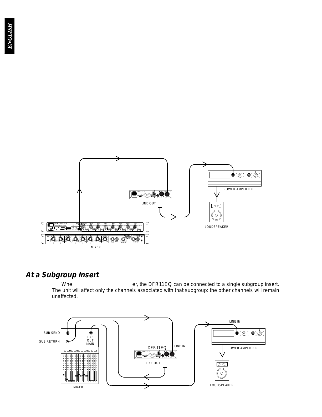
Between the Mixer Main Output and the Power Amplifier
The
DFR1
1EQ is most commonly placed between the main output of a mixer and the input of
power
the
amplifier
DFR1
. At the main output, the unit will af
1EQ as a feedback reducer and as an equalizer
example, delay or reverb ef
1EQ.
fect all input channels. This setup is ideal for using
LINE
DFR11EQ
IN
fects devices) should be placed before the
.
one
a
LINE IN
POWER AMPLIFIER
LINE OUT
ÑÑÑ
MIXER
Ñ
ÑÑÑ
At a Subgroup Insert
When
using a multiple bus mixer, the DFR1
The unit will af
unaffected.
SUB SEND
SUB RETURN
fect only the channels associated with that
LINE
OUT
MAIN
LINE OUT
DFR11EQ
LOUDSPEAKER
1EQ can be connected to a single subgroup insert.
subgroup:
LINE
IN
the other channels will remain
LINE IN
POWER AMPLIFIER
MIXER
LINE OUT
LOUDSPEAKER
10
Page 12
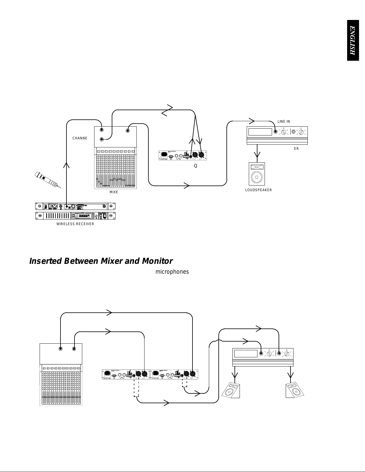
Inserted in an Input Channel
Main Menu
If
only a single microphone is creating feedback problems, the DFR1
channel
of
alone. This is especially useful for wireless microphones, because the constant movement
a performer may bring the microphone too close to the sound reinforcement loudspeakers.
CHANNEL 1 IN
CHANNEL 1
INSERT
LINE
OUT
MAIN
LINE OUT
DFR11EQ
LINE IN
1EQ
can be inserted on that
LINE IN
POWER AMPLIFIER
MIXER
LINE OUT
WIRELESS RECEIVER
Inserted Between Mixer and Monitor
Since
monitor loudspeakers and microphones are usually in close proximity
be
connected to stabilize a monitor system. Place a DFR1
the monitor loudspeaker
each
monitor send.
AUX 2
AUX 1
OUT
OUT
. For multiple monitor mixes, a DFR1
LINE
DFR11EQ
LINE OUT
IN
DFR11EQ
LINE OUT
LOUDSPEAKER
, the DFR1
1EQ on the monitor output which goes to
1EQ should be placed at the output of
LINE IN
LINE IN
LINE IN
MONITOR
POWER AMPLIFIER
MONITOR
LOUDSPEAKERS
1EQ can
MIXER
11
Page 13
VERSION 4 SOFTWARE
Main Menu
Introduction
This
section describes the V
you
to utilize the full features of the Shure DFR1
you can access additional control features to customize the operating characteristics of the feedback
filters. The computer interface also allows access to the built-in digital equalizer, which can be
configured in one of two ways: as a 30-band,
10-band
response
combined.
parametric equalizer
graph for an accurate
In addition, there is a
Minimum Computer Requirements
The
following are the minimum requirements to run the Shure DFR1
One 486DX 50 MHz IBM*-compatible computer (math coprocessor required)
2 MB hard drive space
4 MB RAM
Windows version 3.1x, or greater
1 available RS-232 serial (COM) port
One RS-232 cable to connect the COM port of the computer to the DB-9
connector
of the DFR1
ersion 4 Windows-based computer interface software which allows
. The resulting equalization
display of either the feedback filter response, EQ response, or both
digital delay which can add up to 100 ms of delay from input to output.
1EQ
1EQ. By connecting the DFR1
1
/3-octave, constant-Q, graphic equalizer, or as a
curves can be displayed in the frequency
1EQ to your computer
1EQ software.
,
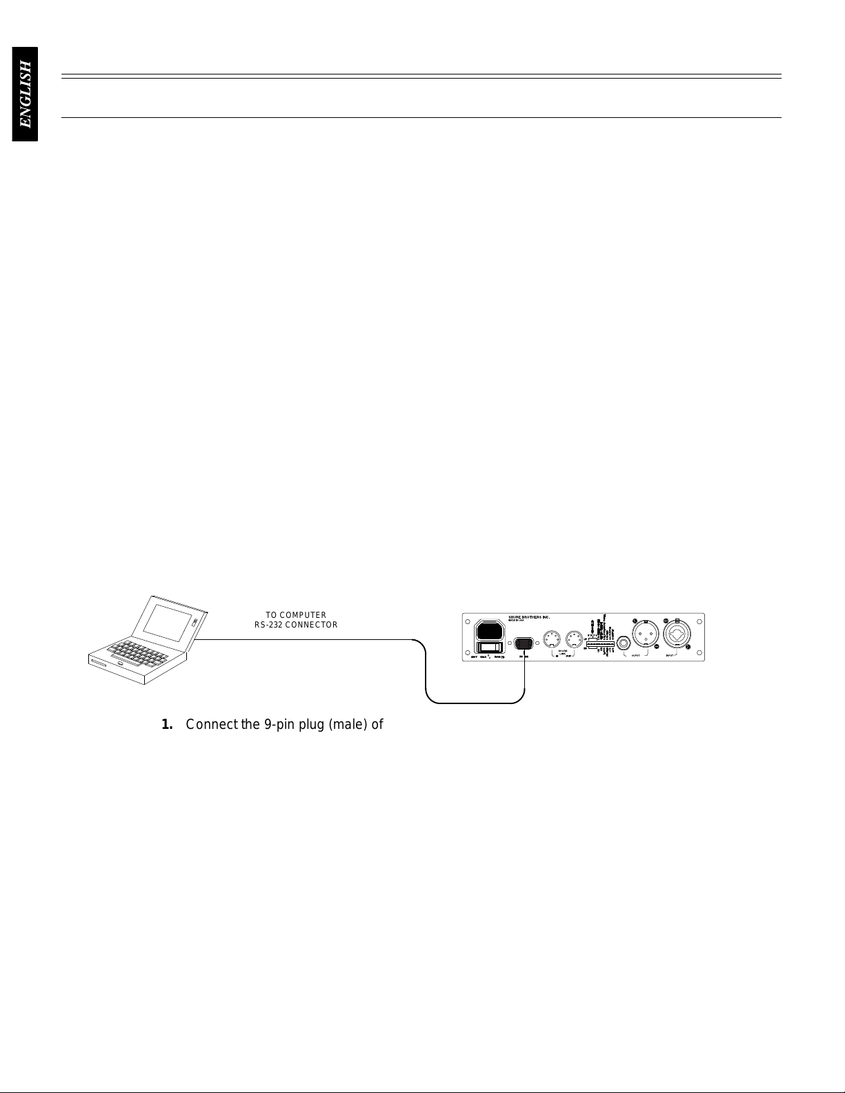
Connecting
the DFR1
Before connecting the DFR11EQ to the computer, determine whether the computer’s RS-232
(COM) port is 9-pin or 25-pin. Use the proper cable (purchased separately). For RS-232 cable
diagrams,
see
Appendix C. Cables and Connectors.
1. Connect
2.
Connect the other end of the cable to the RS-232 port of the computer
the 9-pin plug (male) of the cable to the RS-232 port of the DFR1
Software Installation
1. Insert
2.
3.
4.
the supplied 3.5-in floppy disk into the disk drive of your computer
With Windows Program Manager active, click on the
click on
In the
disk.
Shure Setup will suggest a destination on your hard disk for the DFR1
Setup will check the computer hardware to ensure that a coprocessor is present. Setup
will also prompt you for your name and organizational information.
NOTE: Remember to register your software by filling out and mailing the
enclosed registration card, or online via the Shure World Wide Web site
(“http://www.shure.com”). This will ensure that you receive information about
software
Run...
Run
window
updates with additional features as they become available.
1EQ to a Computer via the RS-232 (COM) Port
TO COMPUTER
RS-232 CONNECTOR
TO DFR11EQ
RS-232 CONNECTOR
(9-PIN MALE)
1EQ.
.
.
File
heading of the main menu, then
, type “a:\setup”, where “a” is the drive containing the Shure Setup
1EQ files. Shure
12
Page 14
The Shure DFR11EQ Program Group
Main Menu
The DFR11EQ program group contains the main application icon, a Windows Help file, and a
Readme file with up-to-date information. To launch the application, double-click on the DFR11EQ
icon.
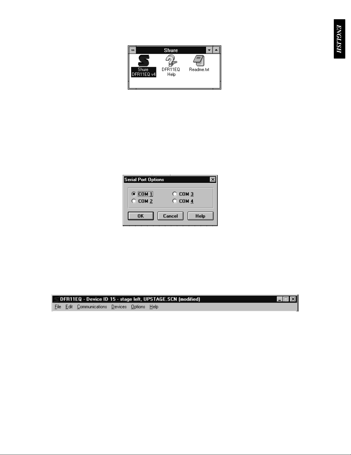
Configuring the Computer Serial Port
1. Launch
2.
Click on
3.
Click on the
the DFR1
Communications
1EQ software.
COM port
in the main menu bar
option of the drop-down menu.
.
Accessing
select the
program
4.
In the
Serial Port Options
5.
Click on the OK button.
NOTE:
to
The COM port selection is saved in the DFR1
be selected again unless you need to change the hardware configuration.
the Connected DFR1
To
bring
the networked DFR1
Connect
searches for each
option of the
window
, select an available COM port on the computer
1EQ file, and will not need
1EQs
1EQ’
s online, click on the
Communications
unit connected in the network, reading the Shure Link Device ID of each.
drop-down menu of the main menu bar. The
CONNECT
button of the DFR panel. Or
.
,
13
Page 15

If You Are Upgrading from Version 3 Software...
Main Menu
Whenever you access a DFR11EQ with Version 3 software, the computer will ask you if you
would
like to upgrade the unit to V
software
unit
was
of
copy
will
stored
will automatically upgrade the unit. If
without upgrading.
In V
ersion 3 of the DFR1
a 16 scene limit. In V
scenes on disk. When V
all scenes saved in the DFR1
be the first 6 letters of the old scene name followed by a 2-digit number
in the description field.
ersion 4, each scene
ersion 4 software is installed over V
ersion 4. If you wish to, click on the OK button and the V
you do not wish to, click on the NO button to access the
1EQ software, scenes were stored in the DFR1
has its own file, so you can store an unlimited number
1EQ.INI file into a subdirectory called SCENES. The file names
ersion 4
1EQ.INI
ersion 3, the setup will automatically
. The full scene name is
files, so there
Accessing Unupgraded V
ersion 3 DFR1
1EQs with V
ersion 4 Software
If
there are DFR1
Version
you
will
Version
the
control,
be
4 will automatically prompt you to upgrade the software when you try to access that
do not wish to update an older unit
still be able to access a DFR1
4 software will not be available. These options will appear greyed out on the interface. See
illustration above. Options which are unavailable under V
delay
, IN/OUT
able to take snapshots of response curves.
1EQ units which were shipped with V
to V
ersion 4 software, click on
1EQ running on V
meters, and parametric equalization. On an unupgraded DFR1
ersion 3, but some of the newer options on
14
ersion 3 software
ersion 3 operation include: output level
in a Shure Link network,
CANCEL
when prompted. Y
unit. If
1EQ, you will
ou
the
Page 16

Overview
Main Menu
CURRENT DEVICE ID SCENE NAME
UNIT NAME ST
ATUS
Main
Menu Bar.
can configure the computer connection to the
DFR11EQ and access other windows for
configuring the DFR11EQ, such as changing
equalizer types and saving scenes. When
connected,
contains the Device ID, name of the current
device,
and scene name.
Through the main
the title bar
menu bar, you
above the main menu bar
Feedback Reducer. The Feedback Reducer
contains many of the same controls available on
the front panel of the DFR11EQ. The Feedback
Reducer section allows you to view and edit the
frequency,
filters.
system
Equalizer.
either a graphic equalizer or as a parametric
equalizer, according to your application. This
module
and
for output levels.
depth, and Q (bandwidth) of individual
There are also controls to Mute the
and Bypass the individual modules.
The equalizer can be set to function as
also contains controls for
the digital delay
sound
Graphic Equalizer
act as a constant-Q, 30-band,
equalizer
per band. Additional high and low frequency cut
filters with a 12 dB/octave rolloff are included for
setting the bandwidth limit of the sound system.
Parametric equalizer
as
equalizer
per
are
driver
with up to
a 10-band, variable-Q, overlapping parametric
with up to
filter. Additional high- and low-shelf/cut filters
included for bandwidth limiting or
level.
mode allows the DFR11EQ to
6 dB of boost and 12 dB of cut
mode allows the unit to act
6 dB of boost and 18 dB of cut
1
/3-octave graphic
loudspeaker
Response Graph. The Frequency Response
Graph allows you to accurately display the
frequency
the equalizer (EQ), or the combined response
(BOTH).
response curve, allowing you to use this as a
reference point as you make changes. This
module also contains the IN and OUT meters,
which
response of the
The snapshot feature stores the present
show the input and output signal levels.
feedback filters (DFR),
15
Page 17

FEEDBACK REDUCER
Main Menu
The
feedback reducer section allows you to add new feedback filters or edit the frequency
depth
of existing ones. Any filter can be individually set to High Q or Low Q. This section also contains
a CONNECT
equalizer,
button for accessing interfaced units, and buttons for bypassing the feedback filters, the
or the delay
.
and
Feedback Reducer Controls
Digital
EQ
Delay
Mute Button and LED
Feedback Reducer (DFR) Bypass Button and LED
Clicking on the DFR bypass button suspends the feedback reducer operation and removes
feedback
its filters from the
reducer is bypassed. This is identical to the front panel BYP
audio path. It does not af
Bypass Button and LED
button
passed.
Clicking
does not af
on the EQ bypass button removes the equalizer filters from the audio path. This
fect feedback reducer operation. When the LED illuminates, the equalizer is by
Bypass and LED
Clicking
illuminate and the sound will pass through unaf
To mute the audio signal of the DFR11EQ, click on the MUTE button. The LED
will illuminate and no sound will pass through.
on the
DELAY
button removes the delay from the audio path. The LED will
fect the equalizer
fected by the delay
. When the LED illuminates, the
ASS button and LED.
-
.
16
Page 18

Clear Filters Button and LED
Main Menu
Click
on the
is
active. The LED illuminates as the DFR clears the filters.
you to clear one or all filters. Click on the CLEAR ONE to clear only the currently
selected filter, or the CLEAR ALL button to clear all filters, then
click
on the
CLEAR
OK
button to clear feedback filters. A dialog box will come up prompting
button to erase a filter(s) The Clear function is active even if
Lock Filters Button and LED
Click on the LOCK button to lock the filters at their current values. The LED
illuminates when the lock is active. The DFR11EQ will not set any new filters or
change the depth of any existing feedback filters. This is identical to the LOCK
button
and LED on the front panel of the DFR1
1EQ.
Feedback Filters Buttons, LEDs, and Related Fields
As on the front panel of the unit, there are 10
LEDs representing each of the 10 feedback
filters. The LEDs illuminate from left to right, with
the LEDs on the left representing the fixed filters.
right
and left arrows to either side of the filter LEDs. This will move the red pointers to select a filter
When
a filter is selected, the current settings of that filter will
fields. LED’
filter
directly by clicking on the arrow buttons beside the FREQ., DEPTH, and TYPE fields.
s underlined in red are set as fixed filters. Y
In
order to view the settings of a specific filter, click on the
appear in the FREQ., DEPTH, and TYPE
ou can click on a filter to select it, then edit that
LOCK
filters
.
FREQ. —
buttons
DEPTH
feeding
type
the desired depth in the field.
TYPE
be
selected individually using this field. Click on the ↓ button beside the field to reveal the two options:
Low
Q and High Q. Select one of these options.
This field displays the frequency center of the selected filter. Click on the ↑ and ↓
to adjust the frequency of the filter, or type the desired frequency in the field.
— This field displays the amount of cut the filter required to stop that frequency from
back. Click on the ↑ and ↓ buttons to
—
This field displays the Q, or width, setting of the selected filter
Connect Button and LED
Clicking the CONNECT button brings the DFR11EQ plugged in to the
computer
LED
operating
LED
illuminates red, the software is reconfiguring a unit as a graphic or parametric equalizer
online,
illuminates green, the connected units are online. When
without the computer interface and the software is running of
adjust the depth of the cut or boost in 5 dB increments, or
along with any other DFR1
. The type of each filter can
1EQs networked via Shure Link. When the
the LED is of
f, the units are
fline. When the
.
17
Page 19

Feedback Reducer Options
Main Menu
The
DFR11EQ Settings
and dynamic filters. T
fixed
1.
Click on
2.
Select the
DIP
Switches Override and Disable
Clicking
Lock/Unlock,
and disable
Lock/Unlock,
DIP switch override does not af
Options
Feedback Reducer
on the
is activated, an X will appear in the box and the High Q/Low Q selection, Front Panel
DIP switches override and disable
and Hold/Update DIP switches to prevent tampering. Once the
and DFR Filter Update/Hold options
window contains options for controlling the DIP switches and setting
o access the
in the main menu bar
... option of the drop-down menu.
fect the input and output level or Device ID DIP switches.
DFR1
1EQ Settings
.
window:
box disables the Filter Bandwidth, Front Panel
DIP switches override
will be controllable only from the computer
. The
Setting High Q or Low Q Filters
The
High Q and Low Q option
of
the unit. For definitions of High Q and Low Q, see
is the same as the Filter Bandwidth DIP switch options on the back
Lock/Unlock the Front Panel
The
Lock/Unlock front panel option is the same as on the Front Panel Lock/Unlock DIP switch.
This
option protects the unit from tampering.
Hold/Update DFR Filters
The Hold/Update DFR Filter option is the same as on the Hold/Update DIP switch. See
Hold/Update
under
Setup for Feedback Control.
Setting Fixed and Dynamic Filters
DFR11EQ feedback filters are set in one of two modes:
these two modes, see
dynamic
filters.
T
o change number of Fixed and Dynamic filters from the
1.
Place the cursor in the
2. T
ype in the desired number of fixed filters. The remaining filters automatically become
dynamic.
3.
Click on the OK button to accept the changes.
DFR11EQ Theory.
Number of Fixed DFR Filters
DFR1
1EQ Theory
Fixed or Dynamic.
The DFR11EQ comes factory preset with 5 fixed and 5
Feedback Reducer Options
field by using the mouse.
.
For definitions of
window:
18
Page 20

EQUALIZER
Main Menu
The Equalizer module of the DFR1
equalizer
for
or as a graphic equalizer
you to set the equalizer type.
1EQ V
, according to your needs. There is an Equalizer Options window
Graphic Equalizer (default)
ersion 4 software can be set to work as a parametric
In
Graphic Equalizer mode, the software allows the DFR1
1
/3-octave
low
sound
graphic equalizer with up to 6 dB of boost and 12 dB of cut per band.
frequency cut
system.
filters with a 12 dB/octave rollof
Setting up the Graphic Equalizer
The
equalizer is already set up in graphic mode when the software is first installed. However
order
to change from parametric to graphic mode:
1.
Click on
2.
Click on
3.
In the
4.
Click on the
5.
If a DFR1
prompts, “The equalizer in the connected DFR1
The
LEDs on the DFR1
unit
to work as a graphic equalizer
Options
Equalizer...
Equalizer Options
1EQ is currently online, click on the
in the main menu bar
window
OK
button.
1EQ will flash on and of
.
f are included for setting the bandwidth limit of the
.
, click on the
f several times while the software reconfigures the
1EQ to act as a constant-Q,
Additional high and
Graphic Equalizer
CONTINUE
1EQ will be reset to graphic mode...”
button.
button when the computer
30-band,
, in
19
Page 21

Combining vs. True 1/3-Octave Equalization
Main Menu
Combining (default)...
band
filters
are combined so that the response curve is smoothed out, creating a more even gradation
of equalization. In the illustrations above, each showing the same section of an equalizer and the
response graph, the one on the left is set to Combining mode. The peaks and troughs on the
response
filters act more independently from each other, as shown in the example on the right above. The
illustration
mode,
Adjusting
graph are smoothed out.
True
1/3 octave...
on the right has the same slider settings as the one on the left, but is set in T
so the peaks and troughs in the resulting response curve are more prominent.
When the graphic equalizer is set
Bands
The DFR11EQ graphic equalizer looks and functions just like a
conventional graphic equalizer. Each slider controls a
centered around the frequency indicated above each slider. When a slider
is
selected, the center of the slider turns green. T
to
drag the slider to the desired level.
Low-Frequency Roll-Off
When the graphic equalizer is setup for combining equalization, the
up for true 1/3-octave equalization, the band
rue 1/3 Octave
1
/3-octave band
o move the slider
, use the mouse
High-Frequency Roll-Off
The
Low frequency roll-off
the
Low frequency roll-of
keys
on the computer keyboard to move this slider
The
High
frequency roll-off
the
High frequency roll-of
keys
on the computer keyboard to move this slider
slider determines the corner frequency of the highpass filter. T
f, drag the slider to the desired frequency. Y
slider determines the corner frequency of the lowpass filter. T
f, drag
the slider to the desired frequency
20
o adjust
ou can also use the ← and
.
. Y
ou can also use the ← and
.
→
o adjust
→
Page 22

Graphic Equalizer Fields and Buttons
Main Menu
Flat
inactive
The
for
the high- and low-rollof
Button
FREQ.
TYPE
GAIN
↑ and ↓ buttons or type a value in the field to adjust the gain or cut of the filter
—
This field displays the frequency center of the selected filter
for graphic equalizer sliders, but is active for the high- and low-frequency sliders.
—
The T
ype field displays the type of equalizer filter: combining or true 1/3-octave.
—
The GAIN field displays the amount of cut or boost in dB applied to the selected filter
f filters.
The Flat
the
high- and low-frequency rollof
the
UNDO
button resets all the equalizer filters sliders back to the 0 dB position and it resets
option from the
f sliders to OUT
EDIT
option in the main menu bar
. The FLA
T button can be undone by selecting
. The ↑ and ↓ buttons are
. This field is inactive
.
.
21
Page 23

Parametric Equalizer
Main Menu
The
equalizer of the DFR1
has
adjustable frequency
rolloff/shelf filters. Parametric filters are represented as dots, while the High- and Low-frequency
filters
are represented as squares. When a filter is selected, the dot representing that filter changes
color
to indicate that it has
, gain, and width. In addition, there are shelving high- and low-frequency
been selected. Parametric filters can be edited using cut, copy
1EQ can be set to work as a 10-band parametric equalizer. Each filter
, and paste.
Setting up the Parametric Equalizer
1. Click
2.
3.
4.
5.
The
equalizer
on
Options
Click on
In the
Click on the
If a DFR1
prompts, “The equalizer in the connected DFR1
LEDs on the DFR1
is being loaded.
Equalizer...
Equalizer Options
1EQ is currently online, click on the
in the main menu bar
window
OK
button.
1EQ will flash on and of
.
, click on the
Parametric Equalizer Fields and Buttons
FREQ. —
buttons
WIDTH
reveal a drop-down menu with the available options. Select one of these to change the width, or type
in
the desired width. If a shelving filter is selected, the fieldchanges to TYPE containing
option. Once the high or low filter cuts
of this field changes to TYPE and it displays the slope of the filter. The slope of the rolloff filter is
adjustable
GAIN
Clicking
shelving filters, the response will shelve at the level of the gain filter
filter
cuts more than –18 dB, the filter becomes a rollof
This field displays the center frequency of the selected filter. Click on the ↑ and ↓
to adjust the frequency of the filter, or type th desired frequency in the field.
—
The WIDTH field displays the width of the selected filter
more than –18 dB, the filter becomes a rollof
from –6 to –24 dB/octave.
—
The GAIN field displays the amount of cut or boost in dB applied to the selected filter
on the ↑ and ↓
buttons will adjust the boost or cut in gain of the filter
Parametric Equalizer
CONTINUE
1EQ will be reset to parametric mode...”
f several times while the code for the parametric
f filter
button when the computer
. However
.
button.
. Clicking on the ↓ button will
SHELF as the
f filter
, so the name
. With the high and low
, once
the
high or low
.
22
Page 24

Adjusting Parametric Filters
Main Menu
NEW
Clear
these
adjusted
all
of the possible bandwidth options. The parametric filters can overlap. However
lapping
Button
Button
Adjusting
colors
and
width. Notice that each filter dot also has wings with two smaller dots. drag
to adjust the Q, or width, of the filter to af
from
the WIDTH field: click on the ↓ button to reveal the drop-down menu which contains
filters may cause the EQ to distort at certain frequencies.
Click
on the
initially
below
The CLEAR
NEW
appears at 1 KHz, 0 dB, 2/3-octave. The number
the
NEW
button resets all the filters.
a parametric filter is simple. Point and click on a filter
to show that it is selected. Then, drag the filter to the desired
level. A parametric filter can be used to cut or boost over a desired band
fect a smaller or larger bandwidth. The Q can also be
button to generate a new parametric filter
button.
High- and Low-Frequency Roll-Off/Shelf Filters
Like
the graphic equalizer
These are the filter squares labelled “H” and “L” — that is, respectively, High and Low. When the
parametric
order to change either filter
shelf/rolloff
extremely useful for boosting flat frequency response, tempering very sibilant vocal microphones, or
enhancing the sound of off-axis lavalier microphones. The illustration below shows how shelving
filters
equalizer if first set, the high- and
filters to cross.
Shelf
—
The Shelf filters can be adjusted from +6 dB to –18 dB in 1/
can be used to boost or cut certain frequencies in a sound system.
, the parametric equalizer of
low-frequency roll-of
, drag the square. The software will not permit the high-
fers both high- and low-frequency filters.
. It will
change
frequency
-
, too many over
. Each new parametric filter
of remaining filters is displayed
f filters are set for a flat response. In
and
low-frequency
dB
increments. Shelving is
2
-
Rolloff
the
filters reach
turns
slope
slopes are nominal values, so slopes at high frequencies will be more steep than those at low
frequencies.
excessive proximity effect, or other unwanted noise is present. The illustration below shows a
response
—
There is an additional step below –18 dB which set the gain of the shelf to cut. When
cut, they change from shelf filters to rollof
into the SLOPE field, and clicking on the ↑ and ↓ buttons will adjust the slope of the
can be adjusted from 6 dB/octave to 24 dB/octave in 6 dB/octave steps. Please not that
Rollof
curve with high- and low-frequency rollof
f filters are ideally used for attenuating the audio signal where extraneous noise,
23
f filters. When in rollof
f filters.
f mode, the GAIN field
rollof
f. The
these
Page 25

Cutting, Copying, and Pasting Parametric Filters
Main Menu
Cutting a Selected Parametric Filter
1. Click
2.
3.
on the desired parametric filter
Click on
Click on
Edit
in the main menu.
Cut.
.
Copying a Selected Parametric Filter
1. Click
2.
3.
on the desired parametric filter
Click on
Click on
Edit
in the main menu bar
Copy.
.
.
Pasting a Selected Parametric Filter
1. Cut
2.
3.
4.
or Copy the desired parametric filter
Go to the unit and scene where you would like to place the filter
Click on
Click on
Edit
in the main menu bar
Paste.
.
.
.
Other Equalizer Options
To
access the Equalizer Options window:
1.
2.
Click on
Click on
Options
Equalizer...
in the main menu bar
.
Hiding and Unhiding Equalizer Panel
1. Click
2.
EQ
Bypass Deactivates Level Control (Default On)
When
feature
without
on the
panel will be hidden. T
the “X”.
Click on the
this is active, the DFR1
allows you to compare the equalized and unequalized sound by using the EQ Bypass button
having to readjust the output level.
Hide equalizer panel
o unhide the equalizer panel, simply click on the box to remove
OK
button.
1EQ will bypass the Level Control when the EQ Bypass is on. This
box. A “X” in the box indicates that the equalizer
24
Page 26

DELAY
Main Menu
There are some potential problems with the arrival of sound in systems utilizing multiple
loudspeakers.
phase
cancellation.
Delay for Solving Time Alignment Problems
Problem:
may
not be enough for a large hall
farther
in front of
the sound from the fill loudspeaker to arrive at the listener earlier than that from the main loudspeaker
To
the audience, it will seem like the
loudspeaker
The DFR1
Some larger sound systems may utilize loudspeaker fill systems.
1EQ Delay is designed to solve two of these problems: time alignment and
because of power limitations. A fill loudspeaker may be placed
the main speaker to augment the sound from the main loudspeaker
sound is coming from the wrong place when the sound from the fill
arrives first.
One loudspeaker
FILL
LOUDSPEAKER
. This may cause
.
MIXER
Solution:
along
the audio path to the amplifier of the fill loudspeaker
The
DFR1
when
it is in time with the sound from the main loudspeaker
arrive
at the audience at the same time. Now
correct
place.
MIXER
The delay in the DFR11EQ can be used to solve this problem. Place a DFR11EQ
1EQ with Delay will hold that audio signal in memory
MAIN
LOUDSPEAKER
MAIN
LOUDSPEAKER
DFR11EQ
DELA
WITH
, the audience will perceive the sound coming from
Y
, then set it to the proper amount of delay
, releasing it to the
fill loudspeaker only
.
, so the sound from both loudspeakers will
the
FILL
LOUDSPEAKER
25
Page 27

Delay for Solving Phase Cancellation Problems
Main Menu
Problem:
Phase cancellation can occur when two loudspeakers are near each other but not
aligned. The two speakers can be seen in the illustration below. The waves represent the sound
coming from each. The sound waves coming from the main and remote loudspeakers are out of
phase.
The
so
Because they are out of phase, the sounds interfere with each other
, degrading audio quality
illustration below shows how sound waves cross, causing phase cancellations.
LOUDSPEAKER
A
AMPLIFIER
MIXER
Solution:
The DFR1
AMPLIFIER
1EQ Delay can be used to stall the signal to loudspeaker B
LOUDSPEAKER
B
just long enough
that when it does come out, it is in phase with the sound from the loudspeaker A. When in phase,
the waves reinforce each other to maintain audio quality. The following illustration shows how the
DFR11EQ
delay works in a sound system.
.
MIXER
AMPLIFIER
DFR11EQ
WITH
LOUDSPEAKER
DELA
Y
A
AMPLIFIER
LOUDSPEAKER
B
26
Page 28

Setting Delay in Milliseconds (Default)
Main Menu
Delay in milliseconds is the default for setting delay in Version 4 software. When set in
milliseconds,
click
on the ↑ and ↓ buttons, or type the amount in the DELA
you do not need to adjust the DFR1
1EQ for temperature. T
Y field.
o set delay in milliseconds,
Setting
Delay by Distance
Setting delay by distance is very easy, but you should account for air temperature. As the
temperature gets hotter the speed at which sound travels increases, so the delay time decreases.
Version
4 software allows you to adjust for dif
T
o set delay in distance:
1.
Click on the button to the right of the
drop-down box.
2.
Select inches, feet, or meters.
3.
Measure the distance from the main loudspeaker to the remote loudspeaker
4.
Click on
5.
Click on
6.
Measure the air temperature.
7.
In the second field, click on the ↓ button to reveal a drop down box. Select Celsius or
Fahrenheit.
8.
In the first field, click on the ↑ and ↓ buttons to lower or raise the temperature. Set this
field to the temperature in the room. The default is 70, a typical room temperature.
9.
Click on the
Options
Delay...
OK
in the main menu bar
button to accept the changes.
ferent temperatures when setting delay by distance.
DELA
Y
field on the main window to reveal a
.
.
27
Page 29

OUTPUT CONTROLS
Main Menu
IN/OUT Level Meters and Output Control
The
IN and OUT level
input
and output in dB. When the levels go into the red, the unit
observing
located near the output controls. Raising or lowering this slider will raise or lower the gain of the
output.
the
output
it,
then click on the ↑ and ↓ buttons next to the GAIN field to raise and lower the levels.
gain loss due to equalization settings. T
As the output level is adjusted, the Response Curve V
current response curve to the new level on
level, the snapshot will remain at the original output level.
To
adjust the output gain, drag drop the
T
o activate the IN/OUT level meters:
1.
Click on
2.
Click on
that it is active.
Options
Display Level Meters
meters located next to the response curve graph display the levels of the
is clipping. This is a useful tool for
o compensate, you can use the OUTPUT slider
iewer will adjust accordingly, moving
the graph. If you take a snapshot before adjusting the
OUTPUT slider
in the main menu bar
option. A check will appear next to this option to indicate
.
. Or
, select the output slider by clicking on
NOTE: While the IN/OUT level meters are running, the NEW indicator on the
DFR11EQ
meters
are active.
unit will continually flicker
. This is normal operation while the IN/OUT
Reversing the Output Signal Polarity
This
option is designed for sound systems where there is a component which inverts the polarity
of
the signal, bringing it
cancellations in the audio. Using this option of the DFR1
invert
the
audio signal in order to compensate. This will save the time and expense spent in wiring
customized
T
1.
2.
cables. When the polarity is reversed, a red ∅ appears over the OUT Meter
o use the DFR1
Click on
Click on
it is active.
out of phase with the rest of the equipment. Inverted polarity can cause phase
1EQ V
1EQ with software V
Options
Reverse Output Polarity
in the main menu bar
ersion 4 as an audio signal polarity inverter:
.
.
A check will appear next to this option to indicate that
ersion 4 software, you can digitally
.
28
Page 30

RESPONSE GRAPH
Main Menu
This section describes how to use the Response Graph, which displays a response curve
showing
Response Curves
DFR
Response Curves
filters.
the ef
fect of the DFR1
Clicking on the DFR button displays the feedback filter frequency response
curve on the graph. This curve shows the response of all deployed feedback
Here you can see the frequency, depth, and Q of each filter
1EQ on the audio signal.
.
EQ
Response Curves
er
and output level control.
Both
can
see how the equalized sound is af
Clicking on the EQ button displays the graphic equalizer frequency
response
Clicking on the BOTH button displays the composite response of the
equalizer
curve on the graph. Use this curve as an aid in setting up the equaliz
and output level control and the deployed feedback filters. Here you
fected by the feedback filters.
-
29
Page 31

Hide
Main Menu
Response Curve Graph
If
you have
the
Windows desktop, you can hide the graph.
1.
2.
3.
4.
Snapshots
finished working on the Response Curve Graph and need to free some space on the
Click on
Click on
Click on the
Click on the
Options
Response Graph...
in the main menu bar
Hide response graph panel
OK
button.
.
box.
One of the new features of software Version 4 is the ability to take snapshots of a frequency
response
changes.
response
curve. A snapshot allows you to view a tracing of the original response curve while making
This is an ef
of the current settings, while the lower curve is the snapshot.
In order to use a snapshot:
1.
Click on the TAKE
2.
Click on the
3.
Make changes to the filter or equalizer settings.
NOTE: If there have been no changes to the curve since the snapshot was
originally taken, the snapshot of the curve is directly under the current curve
because
curve
will change and you will be able to see the snapshot underneath.
fective setup tool. In the illustration above, the upper curve is the frequency
button.
SHOW
they are still exactly the same. Once you make changes, the
button.
current
30
Page 32

SHURE LINK NETWORKS
Main Menu
Shure Link Connections
Up to 16 DFR11EQ’s can be linked together and controlled from a single computer. Each unit
comes
supplied with one 5-pin DIN cable for linking.
DFR11EQ
#1
DFR11EQ #2 DFR11EQ #3
TO
COMPUTER
1. Assign
2.
LINK OUT LINK IN
each unit a Device ID (0 through 15) via the DIP switches on the rear panel (see
Shure Link Device ID
NOTE: All units must have unique Device ID’s. The software will not allow
adjustments
those
Using the supplied 5-pin DIN cable, connect the Shure Link OUT of the first unit (the one
connected directly to the computer) to the Shure Link IN of the next unit. Repeat this
connection for each unit to be networked.
connected from its Shure Link OUT to the Shure Link IN of the first unit.
creates the loop necessary for all of the networked units to communicate with the
computer.
NOTE:
not
MIDI compatible.
to be made to a Device ID which has multiple DFR1
units may be configured dif
Although a standard MIDI cable can be used to link units, Shure Link is
Shure Link Options
Shure Link Device Menu
The
Device
menu displays the following information:
, in the
LINK OUTLINK IN LINK OUTLINK IN
Hardware
section of this manual).
ferently.
1EQ’
s, because
The last unit in the chain should be
This
Device ID. This column lists all the Device ID’s
that are active in the network. The Device ID is
assigned through the DIP switches. See
Link Device ID
also
Unit Name.
Scene. This column lists the name of the scene
that is active in the device and the status of that
scene if it has been modified. Once a modified
scene
changes.
Shure
under
Introduction.
indicates when there are multiple units.
See
Naming a DFR11EQ.
has been saved to disk, the modified status
NOTE: If there are multiple DFR1
ID will appear grayed out in the menu. Those units will be inaccessible to
computer
may
functions.
assigned
control. The software is designed this way to avoid problems which
occur when multiple units on the same Device ID are performing dif
T
o access multiple units, please make sure that each unit has been
a dif
ferent Device ID.
This column
Configuration. This column lists the signal
processing modules active in that scene. The
modules
1EQ’
s using the same Device ID, that Device
31
are listed in abbreviations as follows:
DFR = Digital Feedback Reducer
GEQ = Graphic Equalizer
PEQ = Parametric Equalizer
DL
Y = Delay
3X = DFR1
DFR MEM ERR = Corrupted unit
1EQ V
ersion 3.X
ferent
Page 33

Shure Link Device Selection
Main Menu
In
order to select a Device ID on a Shure Link network:
1.
Click on
2.
In the Device menu, click on the desired Device ID.
The Device ID will appear beside the DFR11EQ heading in the title bar at the top of the main
window,
indicating that the unit with that Device ID will receive computer commands.
Device
in the main menu.
Naming
a DFR1
Devices
In order to name a DFR1
1.
2.
3.
4.
1EQ
can be named...
Click on
In the Device menu, click on
In the
Click on the
Device
Name Device
MAINTENANCE
Scenes
Once
a DFR1
stored
on disk as a Scene. Although
memory,
units require similar settings. Scenes are also useful for multi-purpose sound system, or events
which
other scenes can be saved to disk. Scenes are useful for reducing setup time when multiple
require changing settings “on the fly”.
1EQ has been set up with a desired combination of
1EQ in a network:
in the main menu.
Name Device...
window
OK
button. The name will appear in the title bar
, type in the desired name.
the DFR1
1EQ automatically saves the current scene in internal
The
Name Device
window will appear
.
settings, these settings can be
.
To
Save a Scene to Disk
To Recall a Scene from Disk
Scenes
1.
2.
3.
4.
5.
Once
and
recall it to a DFR1
1.
2.
3.
4.
5.
6.
are saved with the extension .SCN. To save a scene:
Click on
Select the
In the
In the
Click on the
a scene has been saved, the Windows software can be used to reload that scene from disk
Click on
Select the
Select
On the
Select the desired scene name.
Click on the OK button.
File
in the main menu bar
Save Scene
Description
File Name
File
Recall Scene...
Scene
field, type a description of the scene
field, type the name of the scene.
OK
button.
1EQ. T
in the main menu bar
Scenes...
option of the drop-down menu.
window
.
... option of the drop-down menu.
.
o recall a scene:
.
, select the desired scene.
32
Page 34

Customizing Graph Colors
Main Menu
The
graph colors on the V
This
can help make the display more visible or aesthetically
on
the interface:
1.
Click on
2.
Click on
3.
In the
4.
In the field just below the Parametric Graph/Response Graph buttons, click on the
button.
5.
In the drop down menu, select the item you would like to assign a new color
below the field will display the selected item.
6.
On the colored squares beside the display
7.
Click on the
NOTE:
the
Options
Colors...
Color Options
OK
The
Parametric
software is configured for graphic equalizer mode.
ersion 4 software interface can be customized to fit individual tastes.
in the main menu bar
window
button.
, select
option of the
pleasing. T
.
Parametric Graph
, select the desired color
Color Options
window will be disabled if
o change the color of an item
or
Response Graph.
. The space
.
↓
Exiting the DFR11EQ Application
To Exit
1. Click
2.
Select the
on
File
in the main menu bar
Exit
option of the drop-down menu.
.
33
Page 35

Printing DFR11EQ Settings
Main Menu
If
you are documenting a sound system, the DFR1
hardcopy
report showing the settings of a selected unit. T
1.
Click on
2.
Click on
3.
Select any of the desired print options available.
4.
Click on the button of the
then select a printer
5.
Click on the
File
in the main menu bar
Print...
.
OK
button.
Name:
1EQ V
ersion 4 of
o print out a hardcopy of this report:
.
field to display a drop-down list of available printers,
fers the option of printing out a
34
Page 36

APPENDIX A. SPECIFICATIONS
Main Menu
Frequency Response
20 to 20k Hz ± 1.0 dB re 1 kHz
Dynamic Range
104 dB minimum, A-weighted, 20 Hz to 20 kHz
Sampling Rate
48 kHz
Digital-to-Analog, Analog-to-Digital Conversion
20 bit resolution
Voltage Gain
–1 dB ± 1dB (power off)
0 dB ± 2 dB (equal input and output sensitivities)
12 dB ± 2 dB (input –10 dBV, output +4 dBu)
–12 dB ± 2 dB (input +4 dBu, output –10 dBv)
Impedance
Input: 47 kΩ ± 20% actual
Output: 120 Ω ± 20% actual
Input Clipping Level
+18 dBu minimum (at +4 dBu setting)
+6 dBu minimum (at –10 dBV setting)
Output Clipping Level
+18 dBu minimum (at +4 dBu setting)
+6 dBu minimum (at –10 dBV setting)
T
otal Harmonic Distortion
< 0.05% at 1 kHz, +4 dBu, 20 to 20 kHz
LED Signal Indicators
Clip: 6 dB down from input clipping
Propagation Delay from Input to Ouput
< 1.0 ms, all filters set to Flat (0 ms delay setting)
Polarity
Input to output: non-inverting
XLR: pin 2 positive with respect to pin 3
1
/4-in. TRS: tip positive with respect to ring
Operating V
DFR11EQ: 108 to 132 Vac, 50/60 Hz, 50 mA max
DFR11EQE: 216 to 264 Vac, 50/60 Hz, 25 mA max
NOTE:
power supply when the POWER switch is in the Off
position.
Temperature
Operating: 0_ to 60_ C (32_ to 140
Storage: –30_ to 70_ C (–22_ to 158
Fuse
DFR11EQ
DFR11EQE
In
order to change a blown fuse, remove the power cord
and
oltage
This product is not disconnected from the
Range
_ F)
_ F)
:120 VAC. Fuse: 100 mA, 250V time delay.
: 250 VAC. Fuse: 50 mA, 250V time delay
pry open the drawer with a flathead screwdriver.
FUSE
mains
Dimensions
219 mm x 137 mm x 40 mm
8 5/8 in x 5 3/8 in x 1 3/4 in
Weight
930 g (2.5 lbs)
FEEDBACK FIL
Ten (10)
Hz to 20 kHz
Deployed to 1 Hz resolution of feedback frequency
Deployed in depths of 3 dB, 6 dB, 9 dB, 12 dB, and
18 dB (12.5 Low Q in graphic EQ mode) attenuation
Filter shape variable between HI Q and LOW Q (see
High Q vs. Low Q Filters).
GRAPHIC EQUALIZER
Frequency Bands
30 bands on ISO, 1/3-octave centers
Filter T
1
/3-octave, constant Q
Maximum Boost
6 dB per band
Maximum Cut
12dB
nominal
PARAMETRIC
Frequency Bands
10 bands, variable frequency, variable Q
Boost/Cut Range
+6 dB to –18 dB per band
Q Range
1
/40-octave to 2 octave
Shelf/Rolloff Filters
Shelf, +6 to –18 dB per filter
Rolloff, 6dB, 12dB, 18dB, or 24dB per octave nominal
DELAY
Up to 100 ms
FURNISHED ACCESSORIES
Power Cable (DFR1
Power
5-pin
DIN Shure Link Cable
Single
Dual
Mount Rack Bracket
Straddle
TERS
1
/10-octave adaptive notch filters from 60
ype
per band, high- and
EQUALIZER
1EQ) 95A8389.
Cable (DFR1
Mount Rack Bracket
Bars
1EQE) 95A8247.
. . . . . . . . . . . . . . . . . . . . . . . . . . . .
low-pass filters, 12dB/octave
. . . . . . . . . . . . . . . . . .
. . . . . . . . . . . . . . . .
. . . . . . . . . . . . . . . .
. . . . . . . . . . . . . . . .
. . . . . . . . . . . . . . . . .
95A8676.
53A8450.
53B8442.
53B8443.
35
Page 37

CERTIFICATIONS
t
Main Menu
DFR11EQ: UL Listed and cUL Listed to UL 813 and
CSA C22.2 No. 1. Authorized under Verification
provision
DFR11EQE:
eligible to bear CE marking. Meets European Union
Low Voltage Requirements: VDE GS-Certified to EN
60 950. Meets European Union EMC Emissions
Requirements: EN 50 081-1 (1992) [EN 55022].
Meets
EN
Criterion
meets Criterion B].
INFORMA
Changes or modifications not expressly approved by
Shure Brothers Inc. could void your authority to
operate
This
with
Part
provide reasonable protection against harmful
interference in a residential installation. This
equipment generates, uses and can radiate radio
frequency energy and, if not installed and used in
accordance with the instructions, may cause harmful
interference
of FCC Part 15 as a Class B Digital Device.
Conforms to
European Union
50 082–1 (1992): [RF radiated (IEC 801–3) meets
A; ESD meets Criterion B; EFT (IEC
TION T
equipment has been tested and found to comply
the limits for a Class B digital device, pursuant
15 of the FCC Rules. These limits
O USER
this equipment.
to radio communications.
European Union Directives,
EMC Immunity Requirements
are designed to
However
801–4)
to
, there
is no guarantee that interference will not occur in a
particular installation. If this equipment does cause
harmful interference to radio or television reception,
can
which
and on, the user is encouraged to try to correct the
interference
Reorient
be determined by turning the equipment of
by
one or more of the following measures:
or relocate the receiving antenna.
Increase the separation between the equipment
and receiver
Connect the equipment into an outlet on a circuit
dif
ferent from that to which the receiver is
connected.
Consult the dealer or an experienced radio/TV
technician for help.
This symbol indicates that dangerous voltage
constituting a risk of electric shock is presen
within
This
operating and maintenance instructions in the
literature
.
this unit.
symbol indicates that there are important
accompanying this unit.
f
36
Page 38

APPENDIX B. RACK MOUNTING THE DFR11EQ
Ñ
Main Menu
The
DFR1
1EQ comes in a 1/2-rack chassis specially designed for sturdiness. The sagging and
bending
to
found in most 1/2-rack designs is eliminated — the brackets
ensure that the units will be installed securely
.
and straddle bars are designed
WARNING:
aged.
Single Unit
1. Align
2.
the supplied rack-mount brackets over the holes.
Fasten with the 8 supplied screws.
Dual-Mounted Units
Do not torque the screws too tightly
, or the chassis may be dam
-
1. Align
2.
3.
two units side by side so that the front panels both face the same direction.
Place the supplied straddle bars in the recesses on the top and bottom of the units, so
that they overlap both. Fasten with the supplied screws.
NOTE
: Be sure to use both straddle bars when installing dual units.
Position the rackmount brackets over the holes in the side of the unit. Fasten with the
supplied screws.
Mounting in an Equipment Rack
SINGLE MOUNT
1. Insert
2.
the unit(s) into a 19-inch equipment rack.
Fasten the unit(s) to the rack using all four of the supplied screws.
DUAL MOUNT
37
Page 39

APPENDIX C. CONNECTORS AND CABLES
Main Menu
NOTE: Except for the Shure Link cable, none of the cables shown come
supplied
with the DFR1
Audio Connectors
DFR11EQ Audio Input
1EQ.
DFR11EQ Audio Output
Connector:
(XLR
and
1/4-inch
combined)
Configuration: activ
Actual
Impedance:
Nominal
Input Level:
Maximum
Input Level:
Pin
Assignments:
Voltag
e /
Current/
m P
Phanto
Protection?
ower
XLR (female)
(+
(–1
(+
(–1
Pi
phone plug
e b
alanced activ
47 kΩ 47 kΩ
+
4 dBu
4 i
npu
t l
evel)
–1
0 dBV
0 i
npu
t l
evel)
+1
8 d
Bu
4 i
npu
t l
evel)
+
6 d
BV
0 i
npu
t l
evel)
n 1 = g
round
Pi
n 2 = h
ot
n 3 = cold
Pi
yes yes
+
(+
4 i
(–1
(+
4 i
(–1
ring = cold
sleev
1/4-inch
(female)
e b
alanced
4 dBu
npu
t l
–1
0 d
BV
0 i
npu
t l
+1
8 d
Bu
npu
t l
+
6 d
BV
0 i
npu
t l
Ti
p = h
e = g
evel)
evel)
evel)
evel)
ot
round
Connector:
(XLR
and
1/4-inch
separate)
Configuration: activ
Actual
Impedance:
Nominal
Output Level:
Maximum
Output Level:
Pin
Assignments:
Voltag
e /
Current/
m P
Phanto
Protection?
ower
XLR (male)
cross coupled
(+
(–1
(+
(–1
Pi
phone plug
e b
alanced
120 Ω 120 Ω
+
4 d
Bu
4 o
utpu
t l
evel)
–1
0 d
BV
0 o
utpu
t l
evel)
+1
8 d
Bu
4 o
utpu
t l
evel)
+
6 d
BV
0 o
utpu
t l
evel)
n 1 = g
round
Pi
n 2 = h
ot
n 3 = cold
Pi
yes yes
activ
cross coupled
(+
4 o
(–1
0 o
(+
4 o
(–1
0 o
ring = cold
sleev
1/4-inch
(female)
e b
alanced
+
4 d
Bu
utpu
t l
–1
0 d
BV
utpu
+1
8 d
Bu
utpu
t l
+
6 d
BV
utpu
Ti
p = h
e = g
evel)
t l
evel)
evel)
t l
evel)
ot
round
Audio Cables
The variety of connectors on audio equipment sometimes leads to confusion in cabling. The
diagrams below provide cabling recommendations for most common cabling situations. The
following is not a complete list, only a sample of some of the more commonly used cables and
applications.
given examples. Consult the documentation for that equipment.
XLR (male) to XLR (female)
Some of the equipment in a given sound system may have dif
PIN 2
PIN 3
PIN
PIN 3
ferent pinouts than the
+
1
PIN 1
TYPICAL APPLICA
Mixer Line Out to DFR1
DFR1
–
PIN 2
+
DFR1
DFR1
1EQ Output to Amplifier Input
1EQ Output to Mixer Sub Return
Mixer Send to DFR1
Mixer Sub Send to DFR1
1EQ Output to Mixer Sub Return
TIONS
1EQ Input
1EQ Input
1EQ Input
–
38
Page 40

1
Main Menu
/4-in. to 1/4-in. Balanced
1
/4-in. to 1/4-in. Unbalanced
SLEEVE
SLEEVE
SLEEVE
SLEEVE
TIP
RING –
TIP
RING –
TIP
+
TYPICAL APPLICA
Mixer Line Out to DFR1
DFR1
+
DFR1
DFR1
1EQ Output to Amplifier Input
1EQ Output to Mixer Sub Return
Mixer Send to DFR1
Mixer Sub Send to DFR1
1EQ Output to Mixer Sub Return
TIONS
1EQ Input
1EQ Input
1EQ Input
+
TYPICAL APPLICA
Mixer Line Out to DFR1
DFR1
DFR1
DFR1
1EQ Output to Amplifier Input
1EQ Output to Mixer Sub Return
Mixer Send to DFR1
Mixer Sub Send to DFR1
1EQ Output to Mixer Sub Return
TIONS
1EQ Input
1EQ Input
1EQ Input
1
/4-in. Balanced to 1/4-in. Unbalanced
SLEEVE
SLEEVE
XLR (male) to 1/4-in. Balanced
SLEEVE
TIP
TIP
PIN 2
+
RING –
TIP
+
+
PIN 3
+
–
RING –
PIN
TYPICAL APPLICA
Mixer Line Out to DFR1
DFR1
DFR1
DFR1
1
TYPICAL APPLICA
DFR1
DFR1
DFR1
1EQ Output to Amplifier Input
1EQ Output to Mixer Sub Return
Mixer Send to DFR1
Mixer Sub Send to DFR1
1EQ Output to Mixer Sub Return
Mixer Line Out to DFR1
1EQ Output to Amplifier Input
1EQ Output to Mixer Sub Return
Mixer Send to DFR1
Mixer Sub Send to DFR1
1EQ Output to Mixer Sub Return
TIONS
1EQ Input
1EQ Input
1EQ Input
TIONS
1EQ Input
1EQ Input
1EQ Input
39
TIP
+
Page 41

XLR (female) to 1/4-in. Balanced
E
Main Menu
PIN
PIN 2
1
+
SLEEVE
XLR (female) to 1/4-in. Unbalanced
PIN 3
PIN
PIN 3
–
1
–
SLEEVE
RING –
TIP
TIP
+
+
PIN 2
TYPICAL APPLICA
Mixer Line Out to DFR1
DFR1
DFR1
DFR1
1EQ Output to Amplifier Input
1EQ Output to Mixer Sub Return
Mixer Send to DFR1
Mixer Sub Send to DFR1
1EQ Output to Mixer Sub Return
TIONS
1EQ Input
1EQ Input
1EQ Input
+
TYPICAL APPLICA
Mixer Line Out to DFR1
DFR1
DFR1
DFR1
1EQ Output to Amplifier Input
1EQ Output to Mixer Sub Return
Mixer Send to DFR1
Mixer Sub Send to DFR1
1EQ Output to Mixer Sub Return
TIONS
1EQ Input
1EQ Input
1EQ Input
Y-adapter cable, 1/4-in. Balanced to 1/4-in. Unbalanced
TIP
RING –
+
SLEEVE
RCA to 1/4-in. Unbalanced
SLEEVE
TIP
SLEEVE
+
TIP
+
TYPICAL APPLICA
Mixer Send/Return (Insert) to DFR1
Input and Output
TYPICAL APPLICA
DFR1
1EQ Output to Amplifier Input
TIONS
1
TIONS
40
Page 42

Digital Connectors and Cables
Main Menu
Computer Interface — 9-Pin to 9-Pin RS-232 Cable
Computer
25-PIN FEMALE
TO COMPUTER
9-PIN MALE
TO DFR11EQ
9-PIN FEMALE
TO COMPUTER
9-PIN MALE
TO DFR11EQ
54321
987
6
6
54321
987
COMPUTER 9-PIN RS-232
CONNECTOR MALE
DFR11EQ RS-232
CONNECTOR FEMALE
6
54321
987
54321
987
6
Interface — 9-Pin to 25-Pin RS-232 Cable
11 9
13
25
54321
7
68
1012
54321
68
119713
10 12
FUNCTION
141516 18
COMPUTER 25-PIN RS-232
14151618
202224
1921
17
23
54321
CONNECTOR (MALE)
19 21
17
54321
20 22 24
23
25
—
RX
TX
DTR
GND
DSR
RTS
CTS
987
987
6
DFR11EQ RS-232
CONNECTOR FEMALE
6
—
FUNCTION
—
RX
TX
DTR
GND
DSR
RTS
CTS
—
9-PIN CONNECTOR
PIN #
1
2
3
4
5
6
7
8
9
PIN
#
1
2
3
4
5
6
7
8
9
25-PIN CONNECT
PIN #
8
3
2
20
7
6
4
5
22
OR
Shure Link Cable — 5-Pin DIN Cable (MIDI-compatible cable)
FUNCTION
35241
35241
SHURE LINK IN
—
DATA
SHIELD
DATA
—
35241
35241
SHURE LINK OUT
PIN
#
1
4
2
5
3
41
Page 43

APPENDIX D. KEYBOARD CONTROLS
Main Menu
There
are a number of keyboard controls which you can use in instead of a mouse.
General Controls
HIGHLIGHT
HIGHLIGHT controls from right to left:
PRESS a selected button:
SA
VE a scene:
RECALL a scene:
PRINT the settings of the current unit:
EXIT the program:
FINE ADJUST a parameter:
COARSE ADJUST a filter or slider:
UNDO a clear or flat action:
controls from left to right:
or
or
DELETE a highlighted text:
COPY highlighted text to the clipboard:
CUT highlighted text to the clipboard:
P
ASTE text from the clipboard:
IN/OUT Meters and OUTPUT Slider Controls
RESET
T
FINE ADJUST the output gain:
COARSE ADJUST the output gain:
the OUTPUT slider:
urn the IN/OUT meters ON and OFF:
or
or
42
Page 44

Graphic Equalizer Controls
Main Menu
HIGHLIGHT
RESET a selected slider:
FINE ADJUST the gain of a selected slider:
COARSE ADJUST the gain of a selected slider:
the sliders from left to right:
Parametric Equalizer Controls
RESET
CREA
FINE ADJUST the FREQUENCY of a parametric filter:
a selected parametric filter:
TE a new parametric filter:
or
or
or
or
COARSE ADJUST the FREQUENCY of a parametric filter:
FINE ADJUST the GAIN of a parametric filter:
COARSE ADJUST the GAIN of a parametric filter:
ADJUST the WIDTH of a parametric filter:
CUT a parametric filter:
COPY a parametric filter:
P
ASTE a parametric filter:
DELETE a parametric filter:
or
or
or
or
or
43
Page 45

NOTES
Main Menu
44
 Loading...