

Page 1

Pixel Controller
Highlite International B.V. – Vestastraat 2 – 6468 EX – Kerkrade – the Netherlands
Product code: 44510
USER MANUAL
ENGLISH
V2
Page 2

1
Pixel Controller
Product code: 44510
Preface
Thank you for purchasing this Showtec product.
The purpose of this user manual is to provide instructions for the correct and safe use of this product.
Keep the user manual for future reference as it is an integral part of the product. The user manual shall be
stored at an easily accessible location.
This user manual contains information concerning:
● Safety instructions
● Intended and non-intended use of the device
● Installation and operation of the device
● Maintenance procedures
● Troubleshooting
● Transport, storage and disposal of the device
Non-observance of the instructions in this user manual may result in serious injuries and damage of
property.
©2021 Showtec. All rights reserved.
No part of this document may be copied, published or otherwise reproduced without the prior written
consent of Highlite International.
Design and product specifications are subject to change without prior notice.
For the latest version of this document or for other language versions, please visit our website
www.highlite.com or contact us at service@highlite.com.
Highlite International and its authorized service providers are not liable for any injury, damage, direct or
indirect loss, consequential or economic loss or any other loss arising from the use of, or inability to use or
reliance on the information contained in this document.
Page 3

2
Pixel Controller
Product code: 44510
Table of contents
1. Introduction .......................................................................................................................................................... 4
Before Using the Product .................................................................................................................................. 4
Intended Use ....................................................................................................................................................... 4
Product Lifespan ................................................................................................................................................. 4
Text Conventions ................................................................................................................................................ 4
Symbols and Signal Words ................................................................................................................................ 5
Symbols on the Information Label .................................................................................................................. 5
2. Safety .................................................................................................................................................................... 6
Warnings and Safety Instructions .................................................................................................................... 6
Requirements for the User ................................................................................................................................. 8
3. Description of the Device ................................................................................................................................... 9
Front View ............................................................................................................................................................ 9
Back View ............................................................................................................................................................ 9
3.3. Side View ...........................................................................................................................................................10
Product Specifications ....................................................................................................................................10
Compatibility .....................................................................................................................................................11
Recommended Software ...............................................................................................................................11
Dimensions .........................................................................................................................................................11
4. Installation .......................................................................................................................................................... 12
4.1. Safety Instructions for Installation ..................................................................................................................12
Personal Protective Equipment .....................................................................................................................12
4.3. Installation Site Requirements ........................................................................................................................12
4.4. Rigging ...............................................................................................................................................................12
4.5. Connecting to Power Supply .........................................................................................................................13
4.6. Power Linking of Multiple Devices .................................................................................................................14
5. Setup ................................................................................................................................................................... 14
5.1. Warnings and Precautions .............................................................................................................................14
5.2. DMX Connection ..............................................................................................................................................14
5.2.1. DMX-512 Protocol .......................................................................................................................................14
5.2.2. DMX Cables .................................................................................................................................................15
5.2.3. Master/Slave Setup ....................................................................................................................................16
5.2.4. DMX Linking ..................................................................................................................................................17
5.2.5. DMX Addressing ..........................................................................................................................................18
5.3. Ethernet Connection .......................................................................................................................................18
5.3.1. Art-Net and Kling-Net Protocols ...............................................................................................................18
5.3.2. Network Cables ..........................................................................................................................................18
5.3.3. Art-Net/Kling-Net Setup .............................................................................................................................19
5.3.4. Art-Net Settings ...........................................................................................................................................20
5.3.5. Kling-Net Settings ........................................................................................................................................20
5.3.6. Universe Numbering ...................................................................................................................................21
6. Operation ........................................................................................................................................................... 22
Safety Instructions for Operation ...................................................................................................................22
Control Modes ..................................................................................................................................................22
Control Panel ....................................................................................................................................................23
Start-up ...............................................................................................................................................................23
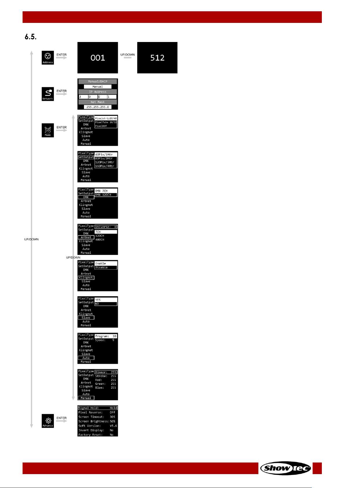
Menu Overview ................................................................................................................................................24
Main Menu Options .........................................................................................................................................25
DMX Address ...............................................................................................................................................25
Network Settings .........................................................................................................................................26
Set Manual/DHCP ..............................................................................................................................26
Set IP Address ......................................................................................................................................26
Set Net Mask .......................................................................................................................................26
Control Modes ............................................................................................................................................27
Page 4
3
Pixel Controller
Product code: 44510
Pixel Type .............................................................................................................................................27
Set Output ...........................................................................................................................................28
DMX .......................................................................................................................................................28
Art-Net ..................................................................................................................................................29
Kling-Net ...............................................................................................................................................29
Slave .....................................................................................................................................................30
Auto ......................................................................................................................................................30
Manual .................................................................................................................................................31
Advanced Settings .....................................................................................................................................31
Signal Hold ...........................................................................................................................................32
Pixel Reverse ........................................................................................................................................32
Screen Timeout ...................................................................................................................................32
Screen Brightness................................................................................................................................32
Software Version .................................................................................................................................32
Invert Display .......................................................................................................................................32
Factory Reset ......................................................................................................................................32
DMX Channels ..................................................................................................................................................33
Pixelstrip 20/40 .............................................................................................................................................33
7 Channels ...........................................................................................................................................33
120, 240, 360, 480 Channels .............................................................................................................34
480 Channels (Art-Net) ......................................................................................................................35
960 Channels (Art-Net) ......................................................................................................................36
1440 Channels (Art-Net) ....................................................................................................................37
1920 Channels (Art-Net) ....................................................................................................................38
Pixeltube 16/32 ............................................................................................................................................39
7 Channels ...........................................................................................................................................39
96, 192, 288, 384, 480 Channels .......................................................................................................40
384 Channels (Art-Net) ......................................................................................................................41
768 Channels (Art-Net) ......................................................................................................................42
1152 Channels (Art-Net) ....................................................................................................................43
1536 Channels (Art-Net) ....................................................................................................................44
1920 Channels (Art-Net) ....................................................................................................................45
PixelDot .........................................................................................................................................................46
7 Channels ...........................................................................................................................................46
30, 60, 90, 120 Channels ....................................................................................................................47
120 Channels (DMX and Art-Net)....................................................................................................48
240 Channels (DMX and Art-Net)....................................................................................................49
360 Channels (DMX and Art-Net)....................................................................................................50
480 Channels (DMX and Art-Net)....................................................................................................51
7. Troubleshooting ................................................................................................................................................. 52
8. Maintenance ..................................................................................................................................................... 53
Safety Instructions for Maintenance .............................................................................................................53
Preventive Maintenance ................................................................................................................................53
Basic Cleaning Instructions .......................................................................................................................53
Corrective Maintenance ................................................................................................................................53
8.3.1. Replacing the Fuse .....................................................................................................................................54
9. Deinstallation, Transportation and Storage .................................................................................................... 55
Instructions for Deinstallation ..........................................................................................................................55
Instructions for Transportation ........................................................................................................................55
Storage ...............................................................................................................................................................55
10. Disposal .............................................................................................................................................................. 55
11. Approval ............................................................................................................................................................. 55
Page 5

4
Pixel Controller
Product code: 44510
1. Introduction
Before Using the Product
Important
Read and follow the instructions in this user manual before installing, operating or
servicing this product.
The manufacturer will not accept liability for any resulting damages caused by the non-observance of
this manual.
After unpacking, check the contents of the box. If any parts are missing or damaged, contact your
Highlite International dealer.
Your shipment includes:
● Showtec Pixel Controller
● Schuko to pro power cable (1,5 m)
● User manual
Fig. 01
Intended Use
This device is intended for use as a pixel controller. It is suitable only for indoor installation. It is not suitable
for households.
Any other use, not mentioned under intended use, is regarded as non-intended and incorrect use.
Product Lifespan
This device is not designed for permanent operation. Disconnect the device from the electrical power
supply when the device is not in operation. This will reduce the wear and will improve the device’s
lifespan.
Text Conventions
Throughout the user manual the following text conventions are used:
● Buttons: All buttons are in bold lettering, for example “Press the UP/DOWN buttons”
● References: References to chapters and parts of the device are in bold lettering, for example:
“Refer to 2. Safety”, “turn the adjustment handle (08)”
● 0–255: Defines a range of values
● Notes: Note: (in bold lettering) is followed by useful information or tips
Page 6

5
Pixel Controller
Product code: 44510
Symbols and Signal Words
Safety notes and warnings are indicated throughout the user manual by safety signs.
Always follow the instructions provided in this user manual.
DANGER
Indicates an imminently hazardous situation which, if not avoided, will result in
death or serious injury.
WARNING
Indicates a potentially hazardous situation which, if not avoided, could result in
death or serious injury.
CAUTION
Indicates a potentially hazardous situation, which, if not avoided, may result in
minor or moderate injury.
Attention
Indicates important information for the correct operation and use of the
product.
Important
Read and observe the instructions in this document.
Electrical hazard
Provides important information about the disposal of this product.
Symbols on the Information Label
This product is provided with an information label. The information label is located at the backside of the
device.
The information label contains the following symbols:
This device is designed for indoor use.
This device shall not be treated as household waste.
This device falls under IEC protection class I.
Read and observe the instructions in the user manual.
Caution: Risk of electric shock. Disconnect input power before opening.
Warning: This appliance must be earthed.
Page 7

6
Pixel Controller
Product code: 44510
2. Safety
Important
Read and follow the instructions in this user manual before installing, operating or
servicing this product.
The manufacturer will not accept liability for any resulting damages caused by the non-observance of
this manual.
Warnings and Safety Instructions
DANGER
Danger for children
For adult use only. The device must be installed beyond the reach of children.
● Do not leave various parts of the packaging (plastic bags, polystyrene foam, nails, etc.) within
children’s reach. Packaging material is a potential source of danger for children.
DANGER
Electric shock caused by dangerous voltage inside
There are areas within the device where dangerous touch voltage may be present.
● Do not open the device or remove any covers.
● Do not operate the device if the covers or the housing are open. Before operation, check if the
housing is firmly closed and all screws are tightly fastened.
● Disconnect the device from electrical power supply before service and maintenance, and when the
device is not in use.
DANGER
Electric shock caused by short-circuit
This device falls under IEC protection class I.
● Make sure that the device is electrically connected to ground (earth). Connect the device only to a
socket-outlet with ground (earth) connection.
● Do not cover the ground (earth) connection.
● Do not bypass the thermostatic switch or fuses.
● For replacement use fuses of the same type and rating only.
● Do not let the power cable come into contact with other cables. Handle the power cable and all
connections with the mains with caution.
● Do not modify, bend, mechanically strain, put pressure on, pull or heat up the power cable.
● Make sure that the power cable is not crimped or damaged. Examine the power cable periodically
for any defects.
● Do not immerse the device in water or other liquids. Do not install the device in a location where
flooding may occur.
● Do not use the device during thunderstorms. Disconnect the device from the electrical power supply
immediately.
Page 8
7
Pixel Controller
Product code: 44510
WARNING
Risk of epileptic shock
Strobe lighting can trigger seizures in photosensitive epilepsy. Sensitive persons should avoid looking at
strobe lights.
Attention
Power supply
● Before connecting the device to the power supply, make sure that the current, voltage and
frequency match the input voltage, current and frequency specified on the information label on the
device.
● Make sure that the cross-sectional area of the extension cords and power cables is sufficient for the
required power consumption of the device.
Attention
General safety
● Do not block the ventilation openings. Without proper heat dissipation and air circulation, the
internal components may overheat. This can result in product damage.
● Do not shake the device. Avoid brute force when installing or operating the device.
● If the device is dropped or struck, disconnect the device from the electrical power supply
immediately.
● If the device is exposed to extreme temperature variations (e.g. after transportation), do not switch it
on immediately. Let the device reach room temperature before switching it on, otherwise it may be
damaged by the formed condensation.
● If the device fails to work properly, discontinue the use immediately.
Attention
This device shall be used only for the purposes it is designed for.
This device is designed to be used as a pixel controller. Any incorrect use may lead to hazardous
situations and result in injuries and material damage.
This device does not contain user-serviceable parts. Unauthorized modifications to the device will render
the warranty void. Such modifications may result in injuries and material damage.
Page 9

8
Pixel Controller
Product code: 44510
Attention
Before each use, examine the device visually for any defects.
Make sure that:
● All screws used for installing the device or parts of the device are tightly fastened and are not
corroded.
● The safety devices are not damaged.
● There are no deformations on housings, fixations and installation points.
● There is no damage to the RJ45 connectors.
● The CAT cables used for connection of the device are not damaged and do not show any material
fatigue.
● The power cables are not damaged and do not show any material fatigue.
Attention
Do not expose the device to conditions that exceed the rated IP class conditions.
This device is IP20 rated. IP (Ingress Protection) 20 class provides protection against solid objects greater
than 12 mm, such as fingers, and no protection against harmful ingress of water.
Requirements for the User
This product may be used by ordinary persons. Maintenance may be carried by ordinary persons.
Installation and service shall be carried out only by instructed or skilled persons. Contact your Highlite
International dealer for more information.
Instructed persons have been instructed and trained by a skilled person, or are supervised by a skilled
person, for specific tasks and work activities associated with the installation, service and maintenance of
this product, so that they can identify risks and take precautions to avoid them.
Skilled persons have training or experience, which enables them to recognize risks and to avoid hazards
associated with the installation, service and maintenance of this product.
Ordinary persons are all persons other than instructed persons and skilled persons. Ordinary persons
include not only users of the product but also any other persons that may have access to the device or
who may be in the vicinity of the device.
Page 10

9
Pixel Controller
Product code: 44510
3. Description of the Device
The Pixel Controller is suitable only for indoor installation (e.g. in hotels or theaters, in order to create a
good ambience in a lobby) and it can be used only with the Pixelstrips 20 and 40, Pixeltubes 16 and 32 or
PixelDots. Each controller can handle those devices divided over 4 outputs.
All Pixelstrips/Pixeltubes/PixelDots can be easily daisy-chained and connected to the Pixel Controller with
a CAT cable. The Pixel Controller can be controlled with DMX, Art-Net and Kling-Net. It can also be used
as a stand-alone controller with built-in programs. When using multiple devices, the built-in programs can
be synchronized due to master/slave function.
Front View
Fig. 02
Pro power connector (Blue) IN
Pro power connector (Gray) OUT
Fuse T6,3A/250 V
Power switch ON/OFF
OLED display + control buttons
Back View
Fig. 03
3-pin DMX connector OUT
5-pin DMX connector OUT
RJ45 connector Art-Net IN/OUT
RJ45 connector Art-Net IN/OUT
5-pin DMX connector IN
3-pin DMX connector IN
Dedicated RJ45 Pixelstrip/Pixeltube/Pixeldot connectors OUT 1–4
Page 11

10
Pixel Controller
Product code: 44510
3.3. Side View
Fig. 04
13) Safety eye
Product Specifications
Model:
Pixel Controller
Electrical:
Input voltage:
100–240 V AC, 50/60 Hz
Power consumption:
230 W
Fuse:
T6,3A/250 V
Physical:
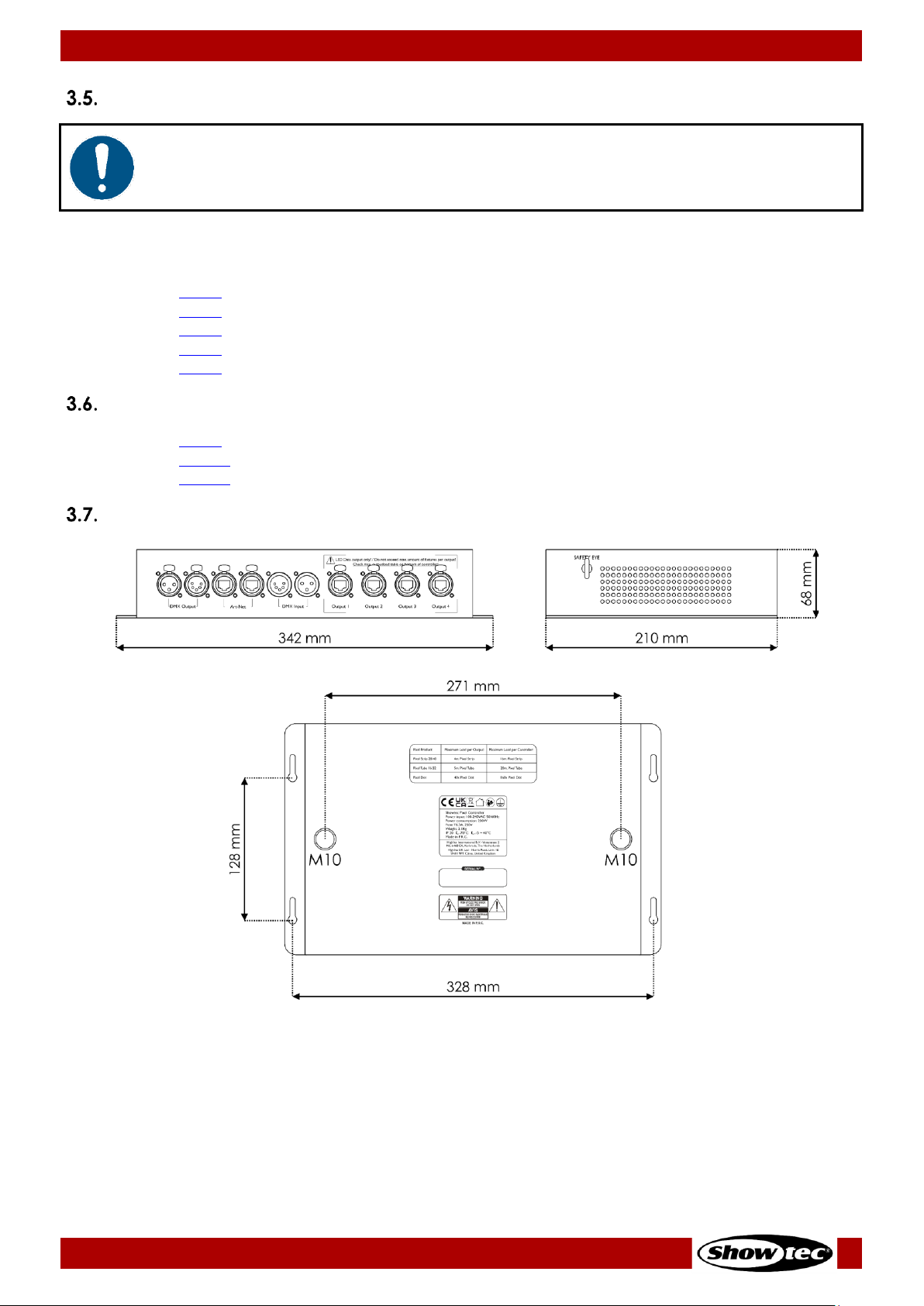
Dimensions:
342 x 210 x 68 mm (L x W x H)
Weight:
2,03 kg
Operation and control:
Control:
Auto, Manual, Master/Slave, DMX-512, Art-Net, Kling-Net
DMX channels:
See 6.7. DMX Channels on pages 33–51 for more information
Control protocols:
DMX-512, Art-Net, Kling-Net
Control panel:
OLED display and buttons
Connections:
Power connections:
Pro power connectors IN/OUT
Input connections:
3-pin/5-pin DMX connectors IN, 2 x Art-Net RJ45 connectors IN/OUT
Output connections:
3-pin/5-pin DMX connectors OUT, 4 x dedicated RJ45 connectors OUT
Maximum cable length:
10 m (CAT-5/CAT-6) from the Pixel Controller to the
Pixelstrip/Pixeltube/PixelDot
Maximum output length:
Pixelstrip 20/40: 4 m per output; 16 m per controller
Pixeltube 16/32: 5 m per output; 20 m per controller
PixelDot: 40 x PixelDot per output; 160 x PixelDot per controller
Construction:
Housing:
Metal
Color:
Black
IP rating:
IP20
Cooling:
Convection
Thermal:
Maximum ambient temperature ta:
40 °C
Maximum housing temperature tc:
70 °C
Page 12
11
Pixel Controller
Product code: 44510
Compatibility
Attention
The Pixel Controller is designed to be operated ONLY with the Pixelstrip 20/40, Pixeltube
16/32 or PixelDot.
The Pixel Controller is delivered without the Pixelstrip/Pixeltube/PixelDot. You need to purchase these
devices separately.
Product code: 44501 (Pixelstrip 20, 50 cm)
Product code: 44502 (Pixelstrip 40, 100 cm)
Product code: 44520 (Pixeltube 32)
Product code: 44521 (Pixeltube 16)
Product code: 44530 (PixelDot)
Recommended Software
Product code: 50180 (Arkaos LED Master)
Product code: 102101 (Arkaos Media Master Express 5.0)
Product code: 102201 (Arkaos Media Master Pro 5.0)
Dimensions
Fig. 05
Page 13
12
Pixel Controller
Product code: 44510
4. Installation
4.1. Safety Instructions for Installation
Attention
Make sure there is enough space for ventilation around the device.
● Do not block the ventilation openings. Without proper heat dissipation and air circulation, the
internal components may overheat. This can result in product damage.
● Do not install near equipment that produces heat, for example amplifiers.
Personal Protective Equipment
During installation and rigging wear personal protective equipment in compliance with the national and
site-specific regulations.
4.3. Installation Site Requirements
● The device must be installed only indoors.
● The device can be placed on a flat surface or mounted to any kind of truss, with clamps and/or
M5/M10 screws for fixed installations.
● The maximum ambient temperature t
a
= 40 °C must never be exceeded.
● The relative humidity must not exceed 50 % with an ambient temperature of 40 °C.
4.4. Rigging
The device can be positioned on a flat surface or mounted to a truss or other rigging structure. Make sure
that all loads are within the pre-determined limits of the supporting structure.
CAUTION
Restrict the access under the work area during rigging and/or derigging.
To mount the device, follow the steps below:
Use clamps to attach the device to the supporting structure, as shown in Fig. 06 on page 13. Make
sure that the device cannot move freely.
02) Secure the device with a secondary suspension, for example a safety cable. Make sure that the
secondary suspension can hold 10 times the weight of the device. If possible, the secondary
suspension should be attached to a supporting structure independent of the primary suspension. Put
the safety cable through the safety eye (13), as shown in Fig. 06 on page 13. You can use the safety
cable supplied with the device.
03) It is also possible to mount the device with 4 x M5 screws. Drill holes in the wall, place the controller on
the wall and tighten the screws.
Page 14

13
Pixel Controller
Product code: 44510
Fig. 06
4.5. Connecting to Power Supply
DANGER
Electric shock caused by short-circuit
The device accepts AC mains power at 100–240 V and 50/60 Hz. Do not supply power at any other
voltage or frequency to the device.
This device falls under IEC protection class I. Make sure that the device is always electrically connected
to the ground (earth).
Before connecting the device to the socket-outlet:
● Make sure that the power supply matches the input voltage specified on the information label on
the device.
● Make sure that the socket-outlet has ground (earth) connection.
Connect the device to the socket-outlet with the power plug.
Page 15
14
Pixel Controller
Product code: 44510
4.6. Power Linking of Multiple Devices
This device supports power linking. Power can be relayed to another device via the power OUT
connector. Note that the input and the output connectors have different designs: one type cannot be
connected to the other.
Power linking of multiple devices must be carried out only by instructed or skilled persons.
WARNING
Incorrect power linking may lead to overload of the electrical circuit and result in serious
injuries and damage of property.
To prevent overload of the electrical circuit, when power linking multiple devices:
● Use cables with sufficient current-carrying capacity. The power cable supplied with the device is not
suitable for power linking of multiple device.
● Make sure that the total current draw of the device and all connected devices does not exceed the
rated capacity of the power cables and the circuit breaker.
● Do not link more devices on one power link than the maximum recommended number.
Maximum recommended number of devices:
● at 100–120 V: 5 devices
● at 200–240 V: 10 devices
5. Setup
5.1. Warnings and Precautions
Attention
Connect all data cables before supplying power.
Disconnect power supply before connecting or disconnecting data cables.
5.2. DMX Connection
5.2.1. DMX-512 Protocol
You need a DMX serial data link to run light shows of one or more devices using a DMX-512 controller or
to run synchronized shows of two or more devices set in a master/slave operating mode.
The Pixel Controller has 3-pin and 5-pin DMX signal IN and OUT connectors.
The pin assignment is as follows:
● 3-pin: pin 1 (ground), pin 2 (-), pin 3 (+)
● 5-pin: pin 1 (ground), pin 2 (-), pin 3 (+), pin 4 (N/C), pin 5 (N/C)
Devices on a serial data link must be daisy-chained in a single line. The number of devices that you can
control on one data link is limited by the combined number of the DMX channels of the connected
devices and the 512 channels available in one DMX universe.
To comply with the TIA-485 standard, no more than 32 devices should be connected on one data link.
In order to connect more than 32 devices on one data link, you must use a DMX optically isolated
splitter/booster, otherwise this may result in deterioration of the DMX signal.
Note:
● Maximum recommended DMX data link distance: 300 m
● Maximum recommended number of devices on a DMX data link: 32 devices
Page 16

15
Pixel Controller
Product code: 44510
5.2.2. DMX Cables
Shielded twisted-pair cables with 3-pin/5-pin XLR connectors must be used for reliable DMX connection.
You can purchase DMX cables directly from your Highlite International dealer or make your own cables.
If you use XLR audio cables for DMX data transmission, this may lead to signal degradation and unreliable
operation of the DMX network.
When you make your own DMX cables, make sure that you connect the pins and wires correctly as
shown in Fig. 07.
Fig. 07
Page 17
16
Pixel Controller
Product code: 44510
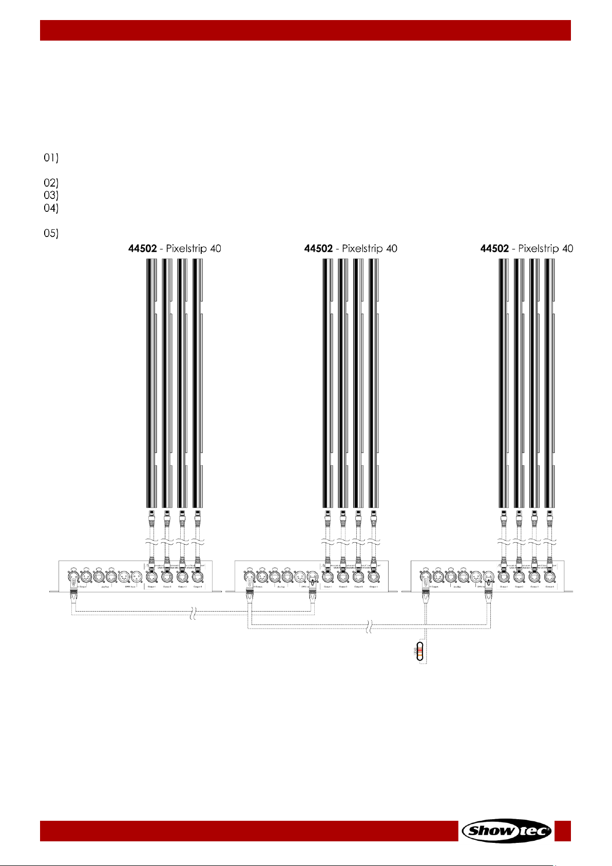
5.2.3. Master/Slave Setup
The Pixel Controller supports master/slave control mode. You can connect the Pixelstrip 20/40 (max. 4 m
per output), Pixeltube 16/32 (max. 5 m per output) or PixelDots (max. 40 devices per output) to the Pixel
Controller. In the example below, the Pixelstrip 40 is connected to the Pixel Controller.
To connect multiple devices in master/slave setup, follow the steps below:
Connect the first device’s DMX OUT connector to the second device’s DMX IN connector with a 3-
pin/5-pin DMX cable.
Repeat step 1 to connect all devices as shown in Fig. 08.
Connect a DMX terminator (120 Ω resistor) to the DMX OUT connector of the last device in the setup.
Set the first device on the data link as a master device. See 6.6.3.6. Slave on page 30 for more
information.
Set the remaining devices as slave devices. See 6.6.3.6. Slave on page 30 for more information.
Fig. 08
Page 18
17
Pixel Controller
Product code: 44510
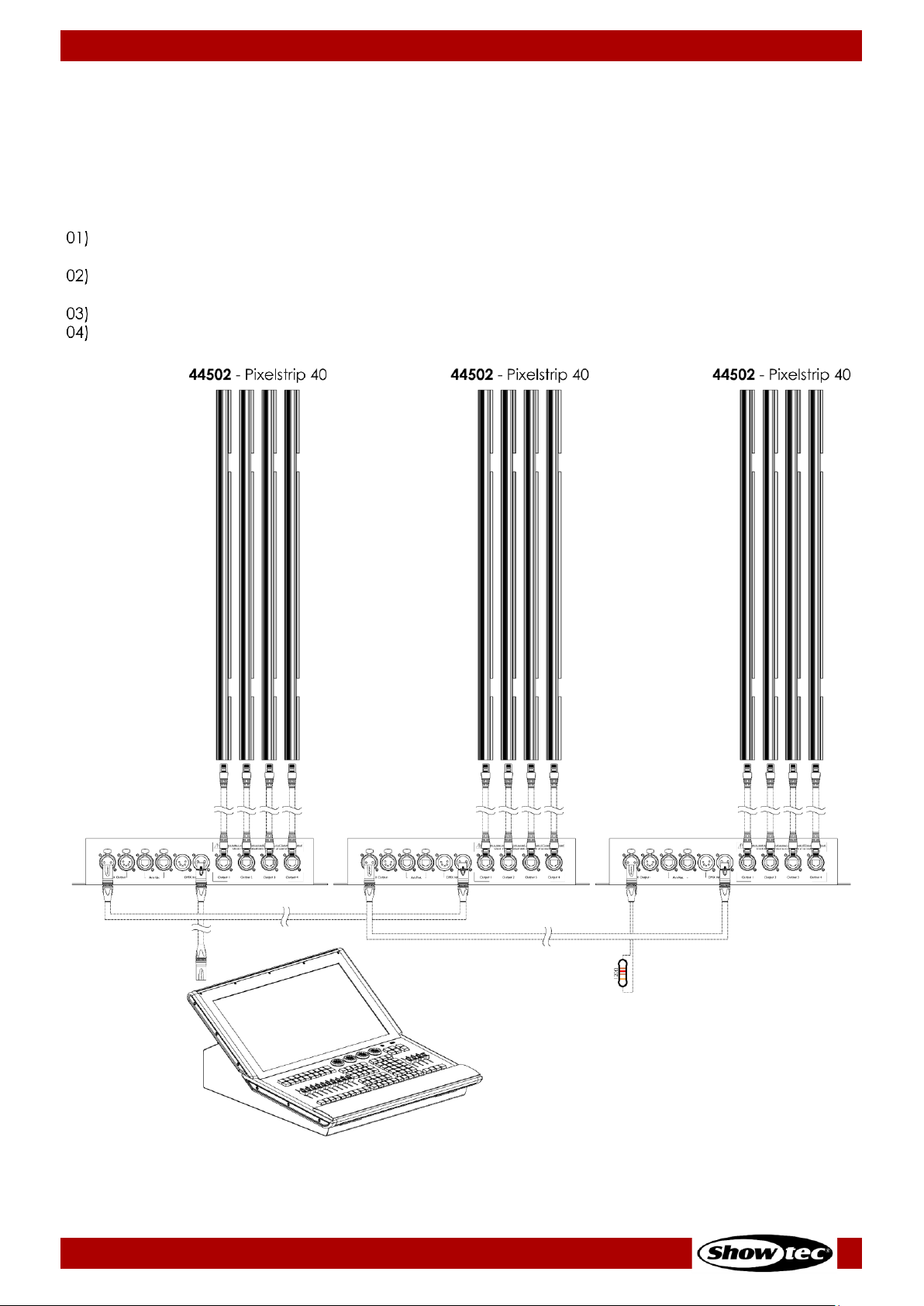
5.2.4. DMX Linking
You can connect the Pixelstrip 20/40 (max. 4 m per output), Pixeltube 16/32 (max. 5 m per output) or
PixelDots (max. 40 devices per output) to the Pixel Controller. In the example below, the Pixelstrip 40 is
connected to the Pixel Controller.
To connect multiple devices on one DMX data link, follow the steps below:
Use a 3-pin/5-pin DMX cable to connect the DMX OUT connector of the lighting controller to the
DMX IN connector of the first device.
Connect the first device’s DMX OUT connector to the second device’s DMX IN connector with a
3-pin/5-pin DMX cable.
Repeat step 2 to connect all devices in a daisy-chain as shown in Fig. 09.
Connect a DMX terminator (120 Ω resistor) to the DMX OUT connector of the last device on the data
link.
Fig. 09
Page 19

18
Pixel Controller
Product code: 44510
5.2.5. DMX Addressing
In a setup with multiple devices, make sure that you set the DMX starting address of each device
correctly. The Pixel Controller has many different personalities, depending on what device is connected
to it: Pixelstrip, Pixeltube or PixelDot. For example, if you want to connect multiple Pixel Controllers on one
data link and use them in 7-channel mode, follow the steps below:
Set the starting address of the 1
st
device on the data link to 1 (001).
Set the starting address of the 2
nd
device on the data link to 8 (008), as 1 + 7 = 8.
Set the starting address of the 3
rd
device on the data link to 15 (015) as 8 + 7 = 15.
Continue assigning the starting addresses of the remaining devices by adding each time 7 to the
previous number.
Make sure that you do not have any overlapping channels in order to control each Pixel Controller
correctly. If two or more devices are addressed similarly, they will work similarly.
5.3. Ethernet Connection
Attention
Connect all data cables before supplying power.
Disconnect power supply before connecting or disconnecting data cables.
5.3.1. Art-Net and Kling-Net Protocols
Art-Net is a protocol that uses TCP/IP to transfer large amount of DMX-512 data over an Ethernet network.
Art-Net 4 can support up to 32768 universes. Art-Net™ Designed by and Copyright Artistic Licence
Holdings Ltd.
Kling-Net is a protocol that allows the creation of a network of LED devices, which are automatically
configured. Kling-Net is independent of DMX-512 or Art-Net protocols. It uses a standard Ethernet
network.
5.3.2. Network Cables
Standard twisted-pair Ethernet cables (CAT-5/CAT-5E/CAT-6) can be used to connect the device to a
computer or to a lighting controller that supports Art-Net or Kling-Net.
If you make your own network cables, make sure that you connect the pins and wires correctly as shown
in Fig. 10. Use RJ45 (8P8C) connectors and patch the cables according to the T568B color standard.
Fig. 10
Page 20
19
Pixel Controller
Product code: 44510
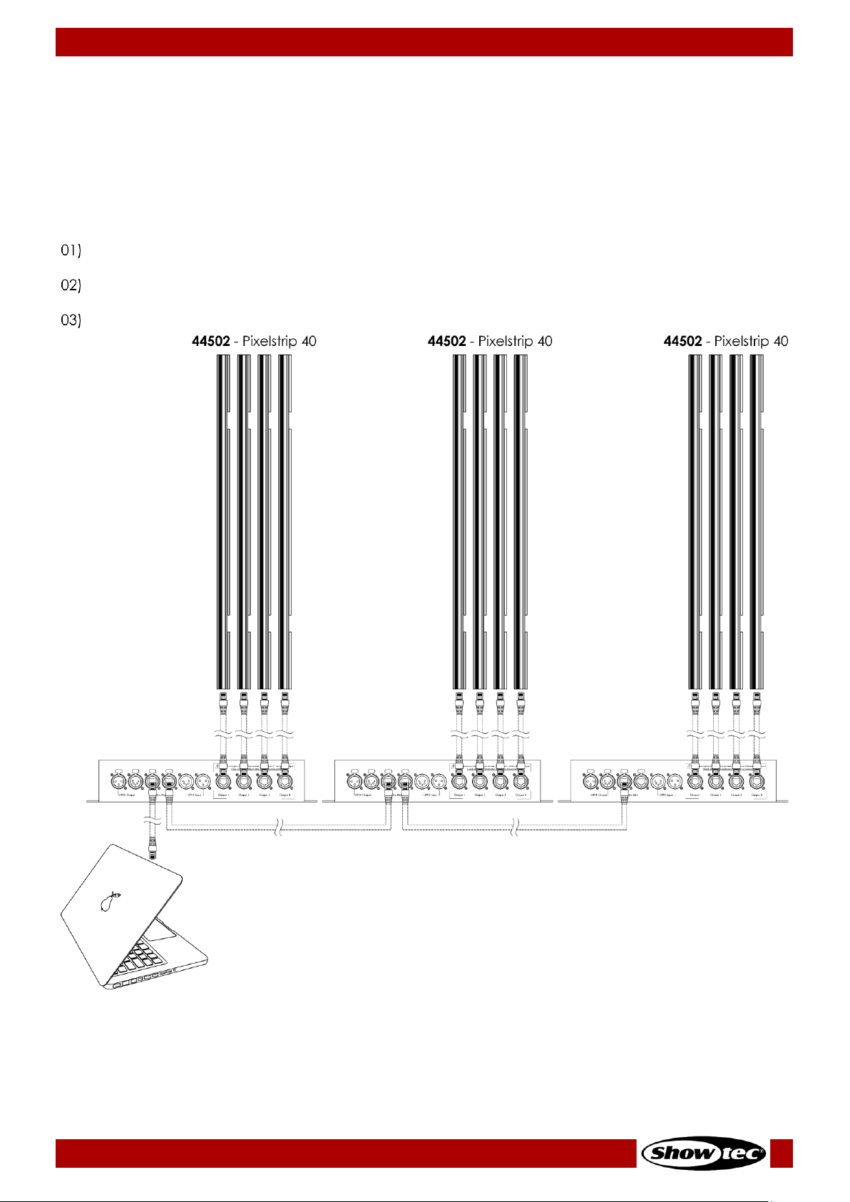
5.3.3. Art-Net/Kling-Net Setup
The Pixel Controller has 2 RJ45 connectors. Either connector can be used as an input and as throughput.
You can connect the Pixelstrip 20/40 (max. 4 m per output), Pixeltube 16/32 (max. 5 m per output) or
PixelDots (max. 40 devices per output) to the Pixel Controller. In the example below, the Pixelstrip 40 is
connected to the Pixel Controller.
To connect multiple devices in an Art-Net/Kling-Net setup, follow the steps below:
Use a CAT-5/CAT-5E/CAT-6 cable to connect the RJ45 connector of the computer/lighting controller
to one of the RJ45 connectors of the first device.
Connect the other RJ45 connector of the first device to the RJ45 connector of the second device
with a CAT-5/CAT-5E/CAT-6 cable.
Repeat step 2 to connect all devices as shown in Fig. 11.
Fig. 11
Page 21

20
Pixel Controller
Product code: 44510
5.3.4. Art-Net Settings
To run your device using Art-Net protocol:
Configure the network address of your computer/lighting controller in the correct range (IP 2.x.x.x,
10.x.x.x or 192.168.x.x and Subnet 255.0.0.0). To change the IP address of the device, refer to 6.6.2.1.
Set Manual/DHCP on page 26 and 6.6.2.2. Set IP Address on page 26. To change the Subnet mask,
refer to 6.6.2.3. Set Net Mask on page 26. Make sure that all devices in the network have unique IP
addresses.
Note: Art-Net 4 supports both DHCP and static addressing.
Select Art-Net Protocol in the Set Net Protocol menu. See 6.6.3.4. Art-Net or 6.6.3.5. Kling-Net on
page 29.
Set the universe. See 5.3.6. Universe Numbering on page 21.
5.3.5. Kling-Net Settings
To run your device using Kling-Net protocol:
Install any Kling-Net-based software on your computer.
Make sure that your computer has a fixed IP address.
Select KlingNet IP in 6.6.2.1. Set Manual/DHCP on page 26. The Kling-Net-based software will
automatically configure the IP address of the device.
Select KlingNet Protocol in the Set Net Protocol menu. See 6.6.3.5. Kling-Net on page 29.
Map the device following the instructions of the Kling-Net-based software.
Page 22

21
Pixel Controller
Product code: 44510
5.3.6. Universe Numbering
If you want to connect more than 5 devices on one data link and use them in 96-channel mode, you will
need to address them on different universes.
Set the DMX starting address of the first 5 devices. Follow the instructions in 5.2.5. DMX Addressing on
page 18.
Set the universe number of the 6
th
device to 001 and the DMX starting address to 001.
Continue addressing the devices, each time increasing the universe number, after the limit of 512
channels for one universe has been reached.
There are 512 channels (1–512) in one universe. 16 consecutive universes (0–15) make up one sub-net. 16
sub-nets (0–15) make up one net. There are in total 128 nets (0–127).
Note:
● In Art-Net, universes are called Port Address and number from 0 to 32767. There are 32768 unique
numbers. This device supports 256 universes (0–255).
15-bit
Port Address
Net
(0–127)
Sub-net
(0–15)
Universe
(0–15)
0 0 0
0
1 0 0 1 2 0 0 2 ...
...
...
...
15 0 0
15
16 0 1 0 17 0 1 1 ...
...
...
...
31 0 1
15
32 0 2 0 33 0 2 1 ...
...
...
...
255 0 15
15
256 1 0
0
257 1 0 1 ...
...
...
...
32766
127
15
14
32767
127
15
15
Make sure that you do not have any overlapping channels in order to control each Pixel Controller
correctly. If two or more devices are addressed similarly, they will work similarly.
Note: If you are using an Art-Net controller that supports Art-Net I or Art-Net II, the Art-Net net
must be set to 0. The net number is available in Art-Net 3 and higher versions of the Art-Net
protocol.
Page 23

22
Pixel Controller
Product code: 44510
6. Operation
Safety Instructions for Operation
Attention
This device must be used only for the purposes it is designed for.
This device is intended for professional use as a pixel controller. It is suitable only for indoor installation. This
device is not suitable for households and for general lighting.
Any other use, not mentioned under intended use, is regarded as non-intended and incorrect use.
Attention
Power supply
Before connecting the device to the power supply, make sure that the current, voltage and frequency
match the input voltage, current and frequency specified on the information label on the device.
Control Modes
The Pixel Controller supports the following control modes:
● Stand-alone: Auto, Manual
● Master/Slave
● DMX-512 See 6.7. DMX Channels on pages 33–51 for more information
● Art-Net, Kling-Net See 6.7. DMX Channels on pages 33–51 for more information
For more information about how to connect the devices, refer to 5. Setup on pages 14–21.
To operate the device manually as a stand-alone device or in a master/slave setup:
Adjust the levels for red, green, blue and strobe in Manual menu. See 6.6.3.8. Manual on page 31 for
more information.
To run one of the built-in programs in auto operation mode without a DMX controller:
Select one of the 30 built-in programs in Auto menu. See 6.6.3.7. Auto on page 30 for more
information.
Set the speed of the built-in chase in Auto menu. See 6.6.3.7. Auto on page 30 for more information.
To operate the device with a DMX controller:
Set the DMX starting address of the device in the DMX Address menu. See 5.2.5. DMX Addressing on
page 18 and 6.6.1. DMX Address on page 25.
02) Select the DMX channel mode. See 6.6.3.3. DMX on page 28 for more information. See 6.7. DMX
Channels on pages 33–51 for complete overview of all DMX channels.
Page 24

23
Pixel Controller
Product code: 44510
Control Panel
A) OLED display
B) UP button
C) DOWN button
D) ENTER button
E) MENU button
Fig. 12
● Use the MENU button to exit the current submenu, to return to the main menu and to return to the
start screen.
● Use the UP/DOWN buttons to navigate through the menus or to increase/decrease numeric values.
● Use the ENTER button to open the desired menu, to confirm your choice or to set the currently
selected value.
Start-up
Upon start-up the display will show the following screen:
When you press the MENU button, the Pixel Controller will show its main menu :
Note: If no button is pressed, the display will turn off. Press any button to turn the display on. See
6.6.4.3. Screen Timeout on page 32 for more information.
Page 25
24
Pixel Controller
Product code: 44510
Menu Overview
Page 26

25
Pixel Controller
Product code: 44510
Main Menu Options
The main menu has the following options:
DMX Address
Network Settings
Pixel Type / Set Output / DMX / Art-Net / Kling-Net / Slave / Auto / Manual
Signal Hold / Pixel Reverse / Screen Timeout / Screen Brightness / Software Version /
Invert Display / Factory Reset
Press the UP/DOWN buttons to navigate through the main menu.
Press the ENTER button to open the submenus.
Press the MENU button to return to the previous screen.
DMX Address
In this menu you can set the DMX starting address of the device.
01) While in main menu, press the UP/DOWN buttons to select .
02) Press the ENTER button to confirm and open this menu.
03) Press the UP/DOWN buttons to select the DMX starting address. The selection range is 001–512.
Press the ENTER button to confirm the selection.
Page 27
26
Pixel Controller
Product code: 44510
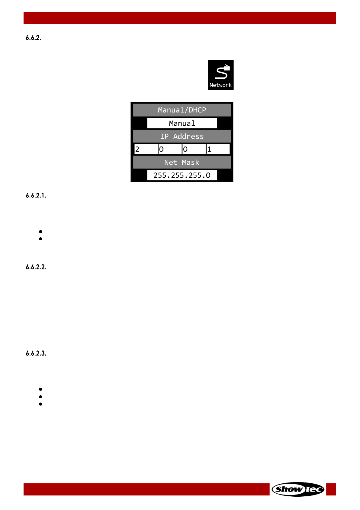
Network Settings
In this menu you can set the network settings.
01) While in main menu, press the UP/DOWN buttons to select .
02) Press the ENTER button to confirm. The display will show:
Set Manual/DHCP
01) Press the UP/DOWN buttons to select MANUAL/DHCP.
02) Press the ENTER button to open the menu.
03) Press the UP/DOWN buttons to select one of the 2 options:
MANUAL: You can enter a desired IP address and net mask.
DHCP: The device will receive its network settings from a DHCP server. If you choose this option,
you will not be able to adjust any settings in this menu.
04) Press the ENTER button to confirm your choice.
Set IP Address
01) Press the UP/DOWN buttons to select IP ADDRESS.
02) Press the ENTER button to open the menu.
03) Press the UP/DOWN buttons to adjust the 1
st
section of the IP address.
04) Press the ENTER button to save changes.
05) Press the UP/DOWN buttons to select the 2
nd
section of the IP address.
06) Press the ENTER button to open the menu.
07) Press the UP/DOWN buttons to adjust the 2
nd
section of the IP address.
08) Press the ENTER button to save changes.
09) Repeat the process to adjust the remaining 2 sections of the IP address.
Set Net Mask
01) Press the UP/DOWN buttons to select NET MASK.
02) Press the ENTER button to open the menu.
03) Press the UP/DOWN buttons to select one of the 3 net mask options:
255.0.0.0
255.255.0.0
255.255.255.0
04) Press the ENTER button to confirm your choice.
Page 28

27
Pixel Controller
Product code: 44510
Control Modes
01) While in main menu, press the UP/DOWN buttons to select .
02) Press the ENTER button to open the menu. The display will show:
03) Press the UP/DOWN buttons to select one of the 8 modes:
PIXEL TYPE
SET OUTPUT
DMX
ART-NET
KLING-NET
SLAVE
AUTO
MANUAL
04) Press the ENTER button to open the desired menu.
Pixel Type
In this menu you can define what device is connected to the Pixel Controller.
01) When the display shows PIXELTYPE, press the ENTER button to open the menu. The display will show:
02) Press the UP/DOWN buttons to select one of the 3 devices:
Pixelstrip 20/40
Pixeltube 16/32
PixelDot
03) Press the ENTER button to confirm your choice. The Pixel Controller will reset and load the options
necessary for the correct functioning of the selected device.
Note: Do not combine Pixelstrips, Pixeltubes and PixelDots on the same Pixel Controller at the same time.
The devices will not work properly. Connect only one of these 3 devices at a time.
Page 29

28
Pixel Controller
Product code: 44510
Set Output
In this menu you can set the output mode.
01) When the display shows SETOUTPUT, press the ENTER button to open the menu. The display will show
the available output options, depending on what device was chosen in 6.6.3.1. Pixel Type on page
27:
02) Press the UP/DOWN buttons to select one of the available output modes.
Note: You can connect the Pixelstrip 20/40 (max. 4 m per output), Pixeltube 16/32 (max. 5 m per output)
or PixelDots (max. 40 devices per output) to the Pixel Controller. Your selected output mode
should correspond with the number and/or total length of the connected devices.
03) Press the ENTER button to confirm your choice.
DMX
In this menu you can set the desired DMX channel mode.
01) When the display shows DMX, press the ENTER button to open the menu. The display will show the
available channel modes, depending on what options were chosen in 6.6.3.1. Pixel Type on page 27
and in 6.6.3.2. Set Output on page 28:
02) Press the UP/DOWN buttons to select one of the available channel modes. See 6.7. DMX Channels on
pages 33–51 for more information.
03) Press the ENTER button to confirm your choice.
Note: The Pixel Controller does not automatically detect whether DMX data signal is received or not.
Activate DMX control.
Page 30

29
Pixel Controller
Product code: 44510
Art-Net
In this menu you can set the Art-Net settings.
01) When the display shows ARTNET, press the ENTER button to open the menu. The display will show the
available Art-Net options, depending on what options were chosen in 6.6.3.1. Pixel Type on page 27
and in 6.6.3.2. Set Output on page 28:
02) Press the UP/DOWN buttons to select UNIVERSE and press the ENTER button to confirm.
03) Press the UP/DOWN buttons to set the universe. The adjustment range is 0–255.
04) Press the ENTER button to save changes.
05) Press the UP/DOWN buttons to select the channel mode selection field and press the ENTER button to
confirm.
06) Press the UP/DOWN buttons to select one of the available channel modes (depending on what
device was chosen in 6.6.3.1. Pixel Type on page 27).
07) Press the ENTER button to confirm your choice.
Note: The Pixel Controller does not automatically detect whether Art-Net data signal is received or not.
Activate Art-Net control.
Kling-Net
In this menu you can activate the Kling-Net settings.
01) When the display shows KLINGNET, press the ENTER button to open the menu. The display will show:
02) Press the UP/DOWN buttons to select ENABLE or DISABLE. If you choose ENABLE, Kling-Net protocol will
be active.
03) Press the ENTER button to confirm your choice.
Note: The Pixel Controller does not automatically detect whether Kling-Net data signal is received or not.
Activate Kling-Net control.
Page 31

30
Pixel Controller
Product code: 44510
Slave
In this menu you can set the device as a slave.
01) When the display shows SLAVE, press the ENTER button to open the menu. The display will show:
02) Press the UP/DOWN buttons to select YES or NO. If you choose YES, the device will react the same as
the master device.
03) Press the ENTER button to confirm your choice.
Auto
In this menu you can run the desired built-in programs.
01) When the display shows AUTO, press the ENTER button to open the menu. The display will show:
02) Press the UP/DOWN buttons to select PROGRAM and press the ENTER button to confirm.
03) Press the UP/DOWN buttons to select one of the 30 built-in programs.
04) Press the ENTER button to confirm your choice.
05) Press the UP/DOWN buttons to select SPEED and press the ENTER button to confirm.
06) Press the UP/DOWN buttons to set the program speed. The adjustment range is 1–9, from slow to fast.
07) Press the ENTER button to save changes.
Page 32

31
Pixel Controller
Product code: 44510
Manual
In this menu you can run Manual mode.
01) When the display shows MANUAL, press the ENTER button to open the menu. The display will show:
02) Press the UP/DOWN buttons to select one of the 5 options:
DIMMER: Dimmer brightness (0–255, from dark to brightest)
STROBE: Strobe frequency (0–4, strobe OFF; 5–255, from low to high frequency)
RED: Red color brightness (0–255, from dark to brightest)
GREEN: Green color brightness (0–255, from dark to brightest)
BLUE: Blue color brightness (0–255, from dark to brightest)
03) Press the ENTER button to open the desired menu.
04) Press the UP/DOWN buttons to adjust the values.
05) Press the ENTER button to save changes.
Note: You can combine RED, GREEN and BLUE to create an infinite range of colors.
Advanced Settings
01) While in main menu, press the UP/DOWN buttons to select .
02) Press the ENTER button to open the menu. The display will show:
03) Press the UP/DOWN buttons to select one of the 7 options:
SIGNAL HOLD
PIXEL REVERSE
SCREEN TIMEOUT
SCREEN BRIGHTNESS
SOFTWARE VERSION (V5.6)
INVERT DISPLAY
FACTORY RESET
04) Press the ENTER button to open the desired option.
05) Press the UP/DOWN buttons to change settings.
06) Press the ENTER button to confirm your choice.
Page 33
32
Pixel Controller
Product code: 44510
Signal Hold
In this menu you can determine the behaviour of the Pixel Controller in case of a DMX failure.
01) Press the ENTER button to open the menu.
02) Press the UP/DOWN buttons to select one of the 2 options:
BLACK: If DMX signal is lost, the device will black its output out.
HOLD: If DMX signal is lost, the device will use the last successfully received DMX signal and will
continue using it until DMX signal reception is restored, in order to ensure undisrupted
performance.
03) Press the ENTER button to confirm your choice.
Pixel Reverse
In this menu you can set the pixel direction.
01) Press the UP/DOWN buttons to select one of the 2 options:
ON: Pixel direction reverse is enabled.
OFF: Pixel direction reverse is disabled.
02) Press the ENTER button to confirm your choice.
Screen Timeout
In this menu you can set the amount of time after which the display will turn off, when no button is
pressed.
01) Press the UP/DOWN buttons to select one of the 3 options: 30 seconds/60 seconds/NEVER.
02) Press the ENTER button to confirm your choice.
Screen Brightness
In this menu you can set the screen brightness.
01) Press the UP/DOWN buttons to select one of the 4 options: 25/50/75/100 %, from dark to brightest.
02) Press the ENTER button to confirm your choice.
Software Version
This menu shows the version of the currently installed software.
Invert Display
In this menu you can set the display inversion.
01) Press the UP/DOWN buttons to select one of the 2 options:
YES: Display inversion is enabled.
NO: Display inversion is disabled.
02) Press the ENTER button to confirm your choice.
Factory Reset
In this menu you can restore the default factory settings.
01) Press the UP/DOWN buttons to select one of the 2 options:
YES: Restore the default factory settings.
NO: Keep the current settings.
02) Press the ENTER button to confirm your choice.
Page 34

33
Pixel Controller
Product code: 44510
DMX Channels
The available DMX channel modes depend on the device connected to the Pixel Controller (see 6.6.3.1.
Pixel Type on page 27) as well as on the selected output mode (see 6.6.3.2. Set Output on page 28).
Pixelstrip 20/40
7 Channels
7 CH
Function
Value
Setting
1
Master Dimmer
000–255
From low to high intensity (0–100 %)
2
Strobe
000–004
Strobe off
005–255
From low to high frequency
3
Red
000–255
From low to high intensity (0–100 %)
4
Green
000–255
From low to high intensity (0–100 %)
5
Blue
000–255
From low to high intensity (0–100 %)
6
Built-in
programs
000–015
Not functional
016–023
Program 1
024–031
Program 2
032–039
Program 3
040–047
Program 4
048–055
Program 5
056–063
Program 6
064–071
Program 7
072–079
Program 8
080–087
Program 9
088–095
Program 10
096–103
Program 11
104–111
Program 12
112–119
Program 13
120–127
Program 14
128–135
Program 15
136–143
Program 16
144–151
Program 17
152–159
Program 18
160–167
Program 19
168–175
Program 20
176–183
Program 21
184–191
Program 22
192–199
Program 23
200–207
Program 24
208–215
Program 25
216–223
Program 26
224–231
Program 27
232–239
Program 28
240–247
Program 29
248–255
Programs 1–29
7
Program speed
000–255
From slow to fast
Note: Make sure that the Master Dimmer channel is open in order to see the light output.
Note: Make sure that the Built-in Programs channel is closed in order to use the Red, Green and
Blue channels.
Page 35

34
Pixel Controller
Product code: 44510
120, 240, 360, 480 Channels
120
CH
240
CH
360
CH
480
CH
Function
Value
Setting
1 1 1 1 Red (pixel 1)
000–255
From low to high intensity (0–100 %)
2 2 2 2 Green (pixel 1)
000–255
From low to high intensity (0–100 %)
3 3 3 3 Blue (pixel 1)
000–255
From low to high intensity (0–100 %)
4 4 4 4 Red (pixel 2)
000–255
From low to high intensity (0–100 %)
5 5 5 5 Green (pixel 2)
000–255
From low to high intensity (0–100 %)
6 6 6 6 Blue (pixel 2)
000–255
From low to high intensity (0–100 %)
7 7 7 7 Red (pixel 3)
000–255
From low to high intensity (0–100 %)
8 8 8 8 Green (pixel 3)
000–255
From low to high intensity (0–100 %)
9 9 9 9 Blue (pixel 3)
000–255
From low to high intensity (0–100 %)
10
10
10
10
Red (pixel 4)
000–255
From low to high intensity (0–100 %)
11
11
11
11
Green (pixel 4)
000–255
From low to high intensity (0–100 %)
12
12
12
12
Blue (pixel 4)
000–255
From low to high intensity (0–100 %)
… … … …
118
118
118
118
Red (pixel 40)
000–255
From low to high intensity (0–100 %)
119
119
119
119
Green (pixel 40)
000–255
From low to high intensity (0–100 %)
120
120
120
120
Blue (pixel 40)
000–255
From low to high intensity (0–100 %)
… … …
238
238
238
Red (pixel 80)
000–255
From low to high intensity (0–100 %)
239
239
239
Green (pixel 80)
000–255
From low to high intensity (0–100 %)
240
240
240
Blue (pixel 80)
000–255
From low to high intensity (0–100 %)
… …
358
358
Red (pixel 120)
000–255
From low to high intensity (0–100 %)
359
359
Green (pixel 120)
000–255
From low to high intensity (0–100 %)
360
360
Blue (pixel 120)
000–255
From low to high intensity (0–100 %)
… 478
Red (pixel 160)
000–255
From low to high intensity (0–100 %)
479
Green (pixel 160)
000–255
From low to high intensity (0–100 %)
480
Blue (pixel 160)
000–255
From low to high intensity (0–100 %)
Page 36

35
Pixel Controller
Product code: 44510
480 Channels (Art-Net)
480 CH
Function
Value
Setting
1
Red (pixel 1, universe 0)
000–255
From low to high intensity (0–100 %)
2
Green (pixel 1, universe 0)
000–255
From low to high intensity (0–100 %)
3
Blue (pixel 1, universe 0)
000–255
From low to high intensity (0–100 %)
4
Red (pixel 2, universe 0)
000–255
From low to high intensity (0–100 %)
5
Green (pixel 2, universe 0)
000–255
From low to high intensity (0–100 %)
6
Blue (pixel 2, universe 0)
000–255
From low to high intensity (0–100 %)
7
Red (pixel 3, universe 0)
000–255
From low to high intensity (0–100 %)
8
Green (pixel 3, universe 0)
000–255
From low to high intensity (0–100 %)
9
Blue (pixel 3, universe 0)
000–255
From low to high intensity (0–100 %)
10
Red (pixel 4, universe 0)
000–255
From low to high intensity (0–100 %)
11
Green (pixel 4, universe 0)
000–255
From low to high intensity (0–100 %)
12
Blue (pixel 4, universe 0)
000–255
From low to high intensity (0–100 %)
… 478
Red (pixel 40, universe 3)
000–255
From low to high intensity (0–100 %)
479
Green (pixel 40, universe 3)
000–255
From low to high intensity (0–100 %)
480
Blue (pixel 40, universe 3)
000–255
From low to high intensity (0–100 %)
Page 37

36
Pixel Controller
Product code: 44510
960 Channels (Art-Net)
960 CH
Function
Value
Setting
1
Red (pixel 1, universe 0)
000–255
From low to high intensity (0–100 %)
2
Green (pixel 1, universe 0)
000–255
From low to high intensity (0–100 %)
3
Blue (pixel 1, universe 0)
000–255
From low to high intensity (0–100 %)
4
Red (pixel 2, universe 0)
000–255
From low to high intensity (0–100 %)
5
Green (pixel 2, universe 0)
000–255
From low to high intensity (0–100 %)
6
Blue (pixel 2, universe 0)
000–255
From low to high intensity (0–100 %)
7
Red (pixel 3, universe 0)
000–255
From low to high intensity (0–100 %)
8
Green (pixel 3, universe 0)
000–255
From low to high intensity (0–100 %)
9
Blue (pixel 3, universe 0)
000–255
From low to high intensity (0–100 %)
10
Red (pixel 4, universe 0)
000–255
From low to high intensity (0–100 %)
11
Green (pixel 4, universe 0)
000–255
From low to high intensity (0–100 %)
12
Blue (pixel 4, universe 0)
000–255
From low to high intensity (0–100 %)
… 958
Red (pixel 80, universe 3)
000–255
From low to high intensity (0–100 %)
959
Green (pixel 80, universe 3)
000–255
From low to high intensity (0–100 %)
960
Blue (pixel 80, universe 3)
000–255
From low to high intensity (0–100 %)
Page 38

37
Pixel Controller
Product code: 44510
1440 Channels (Art-Net)
1440 CH
Function
Value
Setting
1
Red (pixel 1, universe 0)
000–255
From low to high intensity (0–100 %)
2
Green (pixel 1, universe 0)
000–255
From low to high intensity (0–100 %)
3
Blue (pixel 1, universe 0)
000–255
From low to high intensity (0–100 %)
4
Red (pixel 2, universe 0)
000–255
From low to high intensity (0–100 %)
5
Green (pixel 2, universe 0)
000–255
From low to high intensity (0–100 %)
6
Blue (pixel 2, universe 0)
000–255
From low to high intensity (0–100 %)
7
Red (pixel 3, universe 0)
000–255
From low to high intensity (0–100 %)
8
Green (pixel 3, universe 0)
000–255
From low to high intensity (0–100 %)
9
Blue (pixel 3, universe 0)
000–255
From low to high intensity (0–100 %)
10
Red (pixel 4, universe 0)
000–255
From low to high intensity (0–100 %)
11
Green (pixel 4, universe 0)
000–255
From low to high intensity (0–100 %)
12
Blue (pixel 4, universe 0)
000–255
From low to high intensity (0–100 %)
… 1438
Red (pixel 120, universe 3)
000–255
From low to high intensity (0–100 %)
1439
Green (pixel 120, universe 3)
000–255
From low to high intensity (0–100 %)
1440
Blue (pixel 120, universe 3)
000–255
From low to high intensity (0–100 %)
Page 39

38
Pixel Controller
Product code: 44510
1920 Channels (Art-Net)
1920 CH
Function
Value
Setting
1
Red (pixel 1, universe 0)
000–255
From low to high intensity (0–100 %)
2
Green (pixel 1, universe 0)
000–255
From low to high intensity (0–100 %)
3
Blue (pixel 1, universe 0)
000–255
From low to high intensity (0–100 %)
4
Red (pixel 2, universe 0)
000–255
From low to high intensity (0–100 %)
5
Green (pixel 2, universe 0)
000–255
From low to high intensity (0–100 %)
6
Blue (pixel 2, universe 0)
000–255
From low to high intensity (0–100 %)
7
Red (pixel 3, universe 0)
000–255
From low to high intensity (0–100 %)
8
Green (pixel 3, universe 0)
000–255
From low to high intensity (0–100 %)
9
Blue (pixel 3, universe 0)
000–255
From low to high intensity (0–100 %)
10
Red (pixel 4, universe 0)
000–255
From low to high intensity (0–100 %)
11
Green (pixel 4, universe 0)
000–255
From low to high intensity (0–100 %)
12
Blue (pixel 4, universe 0)
000–255
From low to high intensity (0–100 %)
… 1918
Red (pixel 160, universe 3)
000–255
From low to high intensity (0–100 %)
1919
Green (pixel 160, universe 3)
000–255
From low to high intensity (0–100 %)
1920
Blue (pixel 160, universe 3)
000–255
From low to high intensity (0–100 %)
Page 40

39
Pixel Controller
Product code: 44510
Pixeltube 16/32
7 Channels
7 CH
Function
Value
Setting
1
Master Dimmer
000–255
From low to high intensity (0–100 %)
2
Strobe
000–004
Strobe off
005–255
From low to high frequency
3
Red
000–255
From low to high intensity (0–100 %)
4
Green
000–255
From low to high intensity (0–100 %)
5
Blue
000–255
From low to high intensity (0–100 %)
6
Built-in
programs
000–015
Not functional
016–023
Program 1
024–031
Program 2
032–039
Program 3
040–047
Program 4
048–055
Program 5
056–063
Program 6
064–071
Program 7
072–079
Program 8
080–087
Program 9
088–095
Program 10
096–103
Program 11
104–111
Program 12
112–119
Program 13
120–127
Program 14
128–135
Program 15
136–143
Program 16
144–151
Program 17
152–159
Program 18
160–167
Program 19
168–175
Program 20
176–183
Program 21
184–191
Program 22
192–199
Program 23
200–207
Program 24
208–215
Program 25
216–223
Program 26
224–231
Program 27
232–239
Program 28
240–247
Program 29
248–255
Programs 1–29
7
Program speed
000–255
From slow to fast
Note: Make sure that the Master Dimmer channel is open in order to see the light output.
Note: Make sure that the Built-in Programs channel is closed in order to use the Red, Green and
Blue channels.
Page 41

40
Pixel Controller
Product code: 44510
96, 192, 288, 384, 480 Channels
96
CH
192
CH
288
CH
384
CH
480
CH
Function
Value
Setting
1 1 1 1 1
Red (pixel 1)
000–255
From low to high intensity (0–100 %)
2 2 2 2 2
Green (pixel 1)
000–255
From low to high intensity (0–100 %)
3 3 3 3 3
Blue (pixel 1)
000–255
From low to high intensity (0–100 %)
4 4 4 4 4
Red (pixel 2)
000–255
From low to high intensity (0–100 %)
5 5 5 5 5
Green (pixel 2)
000–255
From low to high intensity (0–100 %)
6 6 6 6 6
Blue (pixel 2)
000–255
From low to high intensity (0–100 %)
7 7 7 7 7
Red (pixel 3)
000–255
From low to high intensity (0–100 %)
8 8 8 8 8
Green (pixel 3)
000–255
From low to high intensity (0–100 %)
9 9 9 9 9
Blue (pixel 3)
000–255
From low to high intensity (0–100 %)
10
10
10
10
10
Red (pixel 4)
000–255
From low to high intensity (0–100 %)
11
11
11
11
11
Green (pixel 4)
000–255
From low to high intensity (0–100 %)
12
12
12
12
12
Blue (pixel 4)
000–255
From low to high intensity (0–100 %)
… … … … … 94
94
94
94
94
Red (pixel 32)
000–255
From low to high intensity (0–100 %)
95
95
95
95
95
Green (pixel 32)
000–255
From low to high intensity (0–100 %)
96
96
96
96
96
Blue (pixel 32)
000–255
From low to high intensity (0–100 %)
… … … … 000–255
From low to high intensity (0–100 %)
190
190
190
190
Red (pixel 64)
000–255
From low to high intensity (0–100 %)
191
191
191
191
Green (pixel 64)
000–255
From low to high intensity (0–100 %)
192
192
192
192
Blue (pixel 64)
000–255
From low to high intensity (0–100 %)
… … … 286
286
286
Red (pixel 96)
000–255
From low to high intensity (0–100 %)
287
287
287
Green (pixel 96)
000–255
From low to high intensity (0–100 %)
288
288
288
Blue (pixel 96)
000–255
From low to high intensity (0–100 %)
… …
382
382
Red (pixel 128)
000–255
From low to high intensity (0–100 %)
383
383
Green (pixel 128)
000–255
From low to high intensity (0–100 %)
384
384
Blue (pixel 128)
000–255
From low to high intensity (0–100 %)
… 478
Red (pixel 160)
000–255
From low to high intensity (0–100 %)
479
Green (pixel 160)
000–255
From low to high intensity (0–100 %)
480
Blue (pixel 160)
000–255
From low to high intensity (0–100 %)
Page 42
41
Pixel Controller
Product code: 44510
384 Channels (Art-Net)
384 CH
Function
Value
Setting
1
Red (pixel 1, universe 0)
000–255
From low to high intensity (0–100 %)
2
Green (pixel 1, universe 0)
000–255
From low to high intensity (0–100 %)
3
Blue (pixel 1, universe 0)
000–255
From low to high intensity (0–100 %)
4
Red (pixel 2, universe 0)
000–255
From low to high intensity (0–100 %)
5
Green (pixel 2, universe 0)
000–255
From low to high intensity (0–100 %)
6
Blue (pixel 2, universe 0)
000–255
From low to high intensity (0–100 %)
7
Red (pixel 3, universe 0)
000–255
From low to high intensity (0–100 %)
8
Green (pixel 3, universe 0)
000–255
From low to high intensity (0–100 %)
9
Blue (pixel 3, universe 0)
000–255
From low to high intensity (0–100 %)
10
Red (pixel 4, universe 0)
000–255
From low to high intensity (0–100 %)
11
Green (pixel 4, universe 0)
000–255
From low to high intensity (0–100 %)
12
Blue (pixel 4, universe 0)
000–255
From low to high intensity (0–100 %)
… 382
Red (pixel 32, universe 3)
000–255
From low to high intensity (0–100 %)
383
Green (pixel 32, universe 3)
000–255
From low to high intensity (0–100 %)
384
Blue (pixel 32, universe 3)
000–255
From low to high intensity (0–100 %)
Page 43

42
Pixel Controller
Product code: 44510
768 Channels (Art-Net)
768 CH
Function
Value
Setting
1
Red (pixel 1, universe 0)
000–255
From low to high intensity (0–100 %)
2
Green (pixel 1, universe 0)
000–255
From low to high intensity (0–100 %)
3
Blue (pixel 1, universe 0)
000–255
From low to high intensity (0–100 %)
4
Red (pixel 2, universe 0)
000–255
From low to high intensity (0–100 %)
5
Green (pixel 2, universe 0)
000–255
From low to high intensity (0–100 %)
6
Blue (pixel 2, universe 0)
000–255
From low to high intensity (0–100 %)
7
Red (pixel 3, universe 0)
000–255
From low to high intensity (0–100 %)
8
Green (pixel 3, universe 0)
000–255
From low to high intensity (0–100 %)
9
Blue (pixel 3, universe 0)
000–255
From low to high intensity (0–100 %)
10
Red (pixel 4, universe 0)
000–255
From low to high intensity (0–100 %)
11
Green (pixel 4, universe 0)
000–255
From low to high intensity (0–100 %)
12
Blue (pixel 4, universe 0)
000–255
From low to high intensity (0–100 %)
… 000–255
From low to high intensity (0–100 %)
766
Red (pixel 64, universe 3)
000–255
From low to high intensity (0–100 %)
767
Green (pixel 64, universe 3)
000–255
From low to high intensity (0–100 %)
768
Blue (pixel 64, universe 3)
000–255
From low to high intensity (0–100 %)
Page 44

43
Pixel Controller
Product code: 44510
1152 Channels (Art-Net)
1152 CH
Function
Value
Setting
1
Red (pixel 1, universe 0)
000–255
From low to high intensity (0–100 %)
2
Green (pixel 1, universe 0)
000–255
From low to high intensity (0–100 %)
3
Blue (pixel 1, universe 0)
000–255
From low to high intensity (0–100 %)
4
Red (pixel 2, universe 0)
000–255
From low to high intensity (0–100 %)
5
Green (pixel 2, universe 0)
000–255
From low to high intensity (0–100 %)
6
Blue (pixel 2, universe 0)
000–255
From low to high intensity (0–100 %)
7
Red (pixel 3, universe 0)
000–255
From low to high intensity (0–100 %)
8
Green (pixel 3, universe 0)
000–255
From low to high intensity (0–100 %)
9
Blue (pixel 3, universe 0)
000–255
From low to high intensity (0–100 %)
10
Red (pixel 4, universe 0)
000–255
From low to high intensity (0–100 %)
11
Green (pixel 4, universe 0)
000–255
From low to high intensity (0–100 %)
12
Blue (pixel 4, universe 0)
000–255
From low to high intensity (0–100 %)
… 000–255
From low to high intensity (0–100 %)
1150
Red (pixel 96, universe 3)
000–255
From low to high intensity (0–100 %)
1151
Green (pixel 96, universe 3)
000–255
From low to high intensity (0–100 %)
1152
Blue (pixel 96, universe 3)
000–255
From low to high intensity (0–100 %)
Page 45
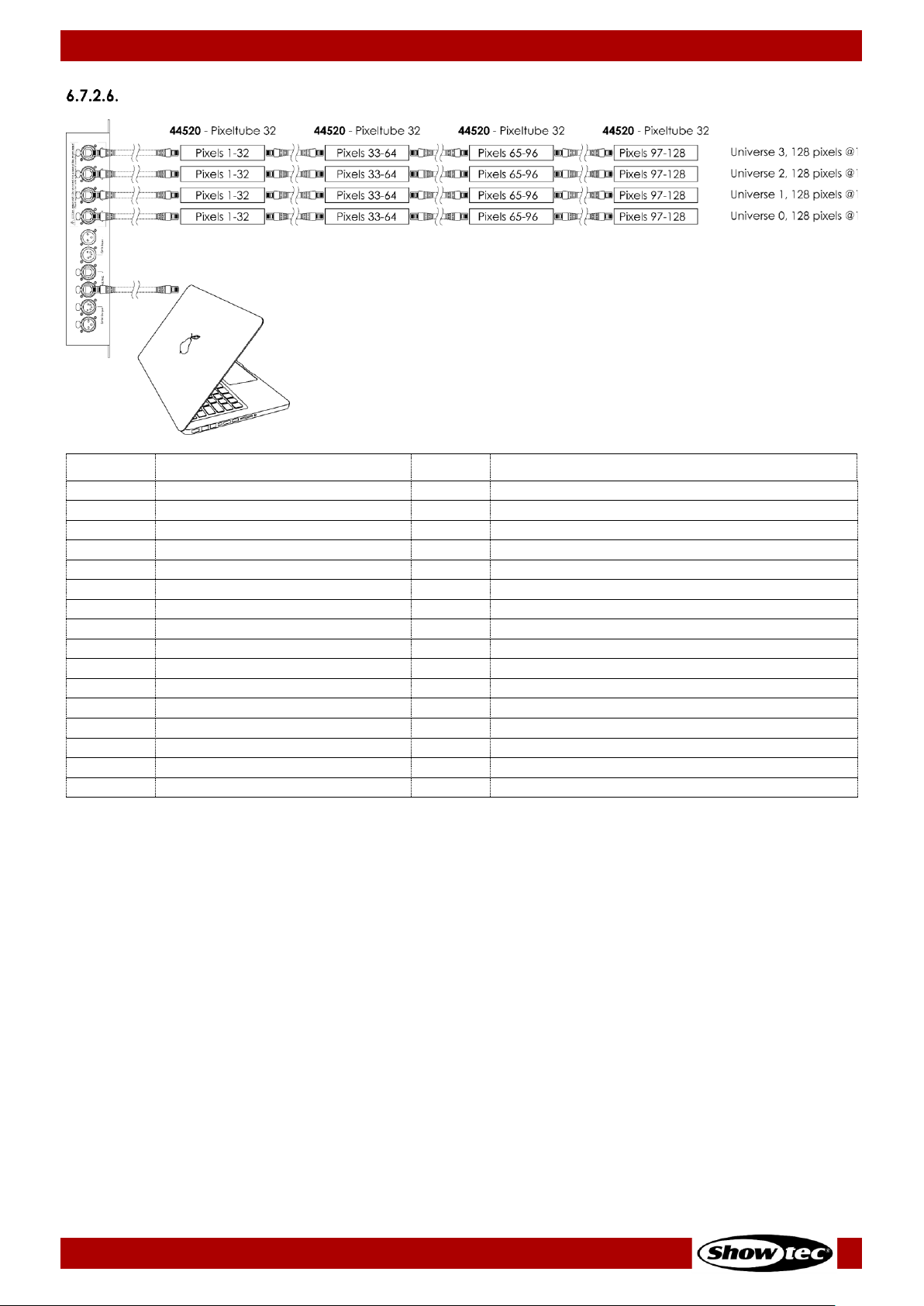
44
Pixel Controller
Product code: 44510
1536 Channels (Art-Net)
1536 CH
Function
Value
Setting
1
Red (pixel 1, universe 0)
000–255
From low to high intensity (0–100 %)
2
Green (pixel 1, universe 0)
000–255
From low to high intensity (0–100 %)
3
Blue (pixel 1, universe 0)
000–255
From low to high intensity (0–100 %)
4
Red (pixel 2, universe 0)
000–255
From low to high intensity (0–100 %)
5
Green (pixel 2, universe 0)
000–255
From low to high intensity (0–100 %)
6
Blue (pixel 2, universe 0)
000–255
From low to high intensity (0–100 %)
7
Red (pixel 3, universe 0)
000–255
From low to high intensity (0–100 %)
8
Green (pixel 3, universe 0)
000–255
From low to high intensity (0–100 %)
9
Blue (pixel 3, universe 0)
000–255
From low to high intensity (0–100 %)
10
Red (pixel 4, universe 0)
000–255
From low to high intensity (0–100 %)
11
Green (pixel 4, universe 0)
000–255
From low to high intensity (0–100 %)
12
Blue (pixel 4, universe 0)
000–255
From low to high intensity (0–100 %)
… 000–255
From low to high intensity (0–100 %)
1534
Red (pixel 128, universe 3)
000–255
From low to high intensity (0–100 %)
1535
Green (pixel 128, universe 3)
000–255
From low to high intensity (0–100 %)
1536
Blue (pixel 128, universe 3)
000–255
From low to high intensity (0–100 %)
Page 46

45
Pixel Controller
Product code: 44510
1920 Channels (Art-Net)
1920 CH
Function
Value
Setting
1
Red (pixel 1, universe 0)
000–255
From low to high intensity (0–100 %)
2
Green (pixel 1, universe 0)
000–255
From low to high intensity (0–100 %)
3
Blue (pixel 1, universe 0)
000–255
From low to high intensity (0–100 %)
4
Red (pixel 2, universe 0)
000–255
From low to high intensity (0–100 %)
5
Green (pixel 2, universe 0)
000–255
From low to high intensity (0–100 %)
6
Blue (pixel 2, universe 0)
000–255
From low to high intensity (0–100 %)
7
Red (pixel 3, universe 0)
000–255
From low to high intensity (0–100 %)
8
Green (pixel 3, universe 0)
000–255
From low to high intensity (0–100 %)
9
Blue (pixel 3, universe 0)
000–255
From low to high intensity (0–100 %)
10
Red (pixel 4, universe 0)
000–255
From low to high intensity (0–100 %)
11
Green (pixel 4, universe 0)
000–255
From low to high intensity (0–100 %)
12
Blue (pixel 4, universe 0)
000–255
From low to high intensity (0–100 %)
… 000–255
From low to high intensity (0–100 %)
1918
Red (pixel 160, universe 3)
000–255
From low to high intensity (0–100 %)
1919
Green (pixel 160, universe 3)
000–255
From low to high intensity (0–100 %)
1920
Blue (pixel 160, universe 3)
000–255
From low to high intensity (0–100 %)
Page 47
46
Pixel Controller
Product code: 44510
PixelDot
7 Channels
7 CH
Function
Value
Setting
1
Master Dimmer
000–255
From low to high intensity (0–100 %)
2
Strobe
000–004
Strobe off
005–255
From low to high frequency
3
Red
000–255
From low to high intensity (0–100 %)
4
Green
000–255
From low to high intensity (0–100 %)
5
Blue
000–255
From low to high intensity (0–100 %)
6
Built-in
programs
000–015
Not functional
016–023
Program 1
024–031
Program 2
032–039
Program 3
040–047
Program 4
048–055
Program 5
056–063
Program 6
064–071
Program 7
072–079
Program 8
080–087
Program 9
088–095
Program 10
096–103
Program 11
104–111
Program 12
112–119
Program 13
120–127
Program 14
128–135
Program 15
136–143
Program 16
144–151
Program 17
152–159
Program 18
160–167
Program 19
168–175
Program 20
176–183
Program 21
184–191
Program 22
192–199
Program 23
200–207
Program 24
208–215
Program 25
216–223
Program 26
224–231
Program 27
232–239
Program 28
240–247
Program 29
248–255
Programs 1–29
7
Program speed
000–255
From slow to fast
Note: Make sure that the Master Dimmer channel is open in order to see the light output.
Note: Make sure that the Built-in Programs channel is closed in order to use the Red, Green and
Blue channels.
Page 48

47
Pixel Controller
Product code: 44510
30, 60, 90, 120 Channels
30
CH
60
CH
90
CH
120
CH
Function
Value
Setting
1 1 1 1 Red (PixelDot 1)
000–255
From low to high intensity (0–100 %)
2 2 2 2 Green (PixelDot 1)
000–255
From low to high intensity (0–100 %)
3 3 3 3 Blue (PixelDot 1)
000–255
From low to high intensity (0–100 %)
4 4 4 4 Red (PixelDot 2)
000–255
From low to high intensity (0–100 %)
5 5 5 5 Green (PixelDot 2)
000–255
From low to high intensity (0–100 %)
6 6 6 6 Blue (PixelDot 2)
000–255
From low to high intensity (0–100 %)
7 7 7 7 Red (PixelDot 3)
000–255
From low to high intensity (0–100 %)
8 8 8 8 Green (PixelDot 3)
000–255
From low to high intensity (0–100 %)
9 9 9 9 Blue (PixelDot 3)
000–255
From low to high intensity (0–100 %)
… … … …
28
28
28
28
Red (PixelDot 10)
000–255
From low to high intensity (0–100 %)
29
29
29
29
Green (PixelDot 10)
000–255
From low to high intensity (0–100 %)
30
30
30
30
Blue (PixelDot 10)
000–255
From low to high intensity (0–100 %)
… … …
000–255
From low to high intensity (0–100 %)
58
58
58
Red (PixelDot 20)
000–255
From low to high intensity (0–100 %)
59
59
59
Green (PixelDot 20)
000–255
From low to high intensity (0–100 %)
60
60
60
Blue (PixelDot 20)
000–255
From low to high intensity (0–100 %)
… …
88
88
Red (PixelDot 30)
000–255
From low to high intensity (0–100 %)
89
89
Green (PixelDot 30)
000–255
From low to high intensity (0–100 %)
90
90
Blue (PixelDot 30)
000–255
From low to high intensity (0–100 %)
…
118
Red (PixelDot 40)
000–255
From low to high intensity (0–100 %)
119
Green (PixelDot 40)
000–255
From low to high intensity (0–100 %)
120
Blue (PixelDot 40)
000–255
From low to high intensity (0–100 %)
Note: The 30-channel is available when 10xPixDOT option was selected in the menu.
Note: The 60-channel is available when 20xPixDOT option was selected in the menu.
Note: The 90-channel is available when 30xPixDOT option was selected in the menu.
Note: The 120-channel is available when 40xPixDOT option was selected in the menu.
See 6.6.3.2. Set Output and 6.6.3.3. DMX on page 28 for more information.
Page 49

48
Pixel Controller
Product code: 44510
120 Channels (DMX and Art-Net)
120 CH
Function
Value
Setting
1
Red (PixelDot 1, output 1)
000–255
From low to high intensity (0–100 %)
2
Green (PixelDot 1, output 1)
000–255
From low to high intensity (0–100 %)
3
Blue (PixelDot 1, output 1)
000–255
From low to high intensity (0–100 %)
4
Red (PixelDot 2, output 1)
000–255
From low to high intensity (0–100 %)
5
Green (PixelDot 2, output 1)
000–255
From low to high intensity (0–100 %)
6
Blue (PixelDot 2, output 1)
000–255
From low to high intensity (0–100 %)
7
Red (PixelDot 3, output 1)
000–255
From low to high intensity (0–100 %)
8
Green (PixelDot 3, output 1)
000–255
From low to high intensity (0–100 %)
9
Blue (PixelDot 3, output 1)
000–255
From low to high intensity (0–100 %)
… 118
Red (PixelDot 10, output 4)
000–255
From low to high intensity (0–100 %)
119
Green (PixelDot 10, output 4)
000–255
From low to high intensity (0–100 %)
120
Blue (PixelDot 10, output 4)
000–255
From low to high intensity (0–100 %)
Note: The 120-channel is available when 10xPixDOT option was selected in the menu.
See 6.6.3.2. Set Output and 6.6.3.3. DMX on page 28 for more information.
Page 50

49
Pixel Controller
Product code: 44510
240 Channels (DMX and Art-Net)
240 CH
Function
Value
Setting
1
Red (PixelDot 1, output 1)
000–255
From low to high intensity (0–100 %)
2
Green (PixelDot 1, output 1)
000–255
From low to high intensity (0–100 %)
3
Blue (PixelDot 1, output 1)
000–255
From low to high intensity (0–100 %)
4
Red (PixelDot 2, output 1)
000–255
From low to high intensity (0–100 %)
5
Green (PixelDot 2, output 1)
000–255
From low to high intensity (0–100 %)
6
Blue (PixelDot 2, output 1)
000–255
From low to high intensity (0–100 %)
7
Red (PixelDot 3, output 1)
000–255
From low to high intensity (0–100 %)
8
Green (PixelDot 3, output 1)
000–255
From low to high intensity (0–100 %)
9
Blue (PixelDot 3, output 1)
000–255
From low to high intensity (0–100 %)
… 238
Red (PixelDot 20, output 4)
000–255
From low to high intensity (0–100 %)
239
Green (PixelDot 20, output 4)
000–255
From low to high intensity (0–100 %)
240
Blue (PixelDot 20, output 4)
000–255
From low to high intensity (0–100 %)
Note: The 240-channel is available when 20xPixDOT option was selected in the menu.
See 6.6.3.2. Set Output and 6.6.3.3. DMX on page 28 for more information.
Page 51

50
Pixel Controller
Product code: 44510
360 Channels (DMX and Art-Net)
360 CH
Function
Value
Setting
1
Red (PixelDot 1, output 1)
000–255
From low to high intensity (0–100 %)
2
Green (PixelDot 1, output 1)
000–255
From low to high intensity (0–100 %)
3
Blue (PixelDot 1, output 1)
000–255
From low to high intensity (0–100 %)
4
Red (PixelDot 2, output 1)
000–255
From low to high intensity (0–100 %)
5
Green (PixelDot 2, output 1)
000–255
From low to high intensity (0–100 %)
6
Blue (PixelDot 2, output 1)
000–255
From low to high intensity (0–100 %)
7
Red (PixelDot 3, output 1)
000–255
From low to high intensity (0–100 %)
8
Green (PixelDot 3, output 1)
000–255
From low to high intensity (0–100 %)
9
Blue (PixelDot 3, output 1)
000–255
From low to high intensity (0–100 %)
…
358
Red (PixelDot 30, output 4)
000–255
From low to high intensity (0–100 %)
359
Green (PixelDot 30, output 4)
000–255
From low to high intensity (0–100 %)
360
Blue (PixelDot 30, output 4)
000–255
From low to high intensity (0–100 %)
Note: The 360-channel is available when 30xPixDOT option was selected in the menu.
See 6.6.3.2. Set Output and 6.6.3.3. DMX on page 28 for more information.
Page 52

51
Pixel Controller
Product code: 44510
480 Channels (DMX and Art-Net)
480 CH
Function
Value
Setting
1
Red (PixelDot 1, output 1)
000–255
From low to high intensity (0–100 %)
2
Green (PixelDot 1, output 1)
000–255
From low to high intensity (0–100 %)
3
Blue (PixelDot 1, output 1)
000–255
From low to high intensity (0–100 %)
4
Red (PixelDot 2, output 1)
000–255
From low to high intensity (0–100 %)
5
Green (PixelDot 2, output 1)
000–255
From low to high intensity (0–100 %)
6
Blue (PixelDot 2, output 1)
000–255
From low to high intensity (0–100 %)
7
Red (PixelDot 3, output 1)
000–255
From low to high intensity (0–100 %)
8
Green (PixelDot 3, output 1)
000–255
From low to high intensity (0–100 %)
9
Blue (PixelDot 3, output 1)
000–255
From low to high intensity (0–100 %)
… 478
Red (PixelDot 40, output 4)
000–255
From low to high intensity (0–100 %)
479
Green (PixelDot 40, output 4)
000–255
From low to high intensity (0–100 %)
480
Blue (PixelDot 40, output 4)
000–255
From low to high intensity (0–100 %)
Note: The 480-channel is available when 40xPixDOT option was selected in the menu.
See 6.6.3.2. Set Output and 6.6.3.3. DMX on page 28 for more information.
Page 53

52
Pixel Controller
Product code: 44510
7. Troubleshooting
This troubleshooting guide contains solutions to problems which can be carried out by an ordinary
person. The device does not contain user-serviceable parts.
Unauthorized modifications to the device will render the warranty void. Such modifications may result in
injuries and material damage.
Refer servicing to instructed or skilled persons. Contact your Highlite International dealer in case the
solution is not described in the table.
Problem
Probable cause(s)
Solution
The device does not
function at all
No power to the device
● Check if power is switched on and
cables are plugged in
Main fuse is blown
● Replace the fuse. See 8.3.1. Replacing
the Fuse on page 54
The device does not
respond to DMX
control
The controller is not connected
● Connect the controller
The signal is reversed. The 3-pin/5pin DMX OUT of the controller does
not match the DMX IN of the
device
● Install a phase-reversing cable
between the controller and the device
The controller is defective
● Try using another controller
The device responds
erratically
The factory settings of the device
are changed
● Reset the device’s parameters to the
default factory settings. See 6.6.4.7.
Factory Reset on page 32
The device responds
erratically to DMX
control
Bad data link connection
● Examine connections and cables.
Correct poor connections. Repair or
replace damaged cables
The data link is not terminated with
a 120 Ω termination plug
● Insert a termination plug in the DMX
OUT connector of the last device on
the link
Incorrect addressing
● Check address settings and correct, if
necessary
In case of a setup with multiple
devices, one of the devices is
defective and disturbs data
transmission on the link
● To find out which device is defective,
bypass one device at a time until
normal operation is restored
No light or LEDs cut
out intermittently
LEDs are damaged
● Disconnect the Pixelstrips, Pixeltubes or
PixelDots and contact your Highlite
International dealer
The power supply settings do not
match local AC voltage and
frequency
● Disconnect the device. Check the
settings and correct, if necessary
Page 54

53
Pixel Controller
Product code: 44510
8. Maintenance
Safety Instructions for Maintenance
DANGER
Electric shock caused by dangerous voltage inside
Preventive Maintenance
Attention
Before each use, examine the device visually for any defects.
Make sure that:
● All screws used for installing the device or parts of the device are tightly fastened and are not
corroded.
● There are no deformations on housings, fixations and installation points.
● The power cables are not damaged and do not show any material fatigue.
Basic Cleaning Instructions
To clean the device, follow the steps below:
Disconnect the device from the electrical power supply.
Allow the device to cool down for 5 minutes.
Clean the device with a soft, lint-free cloth.
Attention
● Do not immerse the device in liquid.
● Do not use alcohol or solvents.
● Make sure that the connections are fully dry before connecting the device to the power supply and
to other devices.
Corrective Maintenance
The device does not contain user-serviceable parts. Do not open the device and do not modify the
device.
Refer repairs and servicing to instructed or skilled persons. Contact your Highlite International dealer for
more information.
Page 55

54
Pixel Controller
Product code: 44510
8.3.1. Replacing the Fuse
DANGER
Electric shock caused by short-circuit
● Do not bypass the thermostatic switch or fuses.
● For replacement use fuses of the same type and rating only.
Power surges, short-circuit or incorrect electrical power supply may cause a fuse to burn out. If the fuse
burns out, the device will not function anymore. If this happens, follow the steps below:
Disconnect the device from the electrical power supply.
01) Allow the device to cool down for 5 minutes.
02) Loosen the fuse cover with a screwdriver and remove the fuse holder.
03) If the fuse is brown or unclear, it is burned out. Remove the old fuse.
04) Insert a new fuse in the fuse holder. Make sure that the type and the rating of the replacement fuse
are the same as the ones specified on the information label of the product.
05) Replace the fuse holder in the opening and tighten the fuse cover.
Page 56

55
Pixel Controller
Product code: 44510
9. Deinstallation, Transportation and Storage
Instructions for Deinstallation
WARNING
Incorrect deinstallation can cause serious injuries and damage of property.
● Let the device cool down before dismounting.
● Disconnect power supply before deinstallation.
● Always observe the national and site-specific regulations during deinstallation and derigging of the
device.
● Wear personal protective equipment in compliance with the national and site-specific regulations.
Instructions for Transportation
● Use the original packaging to transport the device, if possible.
● Always observe the handling instructions printed on the outer carton box, for example: “Handle with
care”, “This side up”, “Fragile”.
Storage
● Clean the device before storing. Follow the cleaning instructions in chapter 8.2.1. Basic Cleaning
Instructions on page 53.
● Store the device in the original packaging, if possible.
10. Disposal
Correct disposal of this product
Waste Electrical and Electronic Equipment
This symbol on the product, its packaging or documents indicates that the product
shall not be treated as household waste. Dispose of this product by handing it to the
respective collection point for recycling of electrical and electronic equipment. This is
to avoid environmental damage or personal injury due to uncontrolled waste
disposal. For more detailed information about recycling of this product contact the
local authorities or the authorized dealer.
11. Approval
Check the respective product page on the website of Highlite International (www.highlite.com) for an
available declaration of conformity.
Page 57

56
Pixel Controller
Product code: 44510
Page 58

57
Pixel Controller
Product code: 44510
Page 59

58
Pixel Controller
Product code: 44510
Page 60

©2021 Showtec
 Loading...