

SHOWTEC Performer Profile IP Q4 User Manual

Performer Profile IP Q4 V1
Highlite International B.V. – Vestastraat 2 – 6468 EX – Kerkrade – the Netherlands
Order code: 33111
MANUAL
ENGLISH

1
Order code: 33111
Performer Profile IP Q4
Table of contents
Warning .................................................................................................................................................................................................... 2
Safety Instructions .............................................................................................................................................................................. 2
Operating Determinations ................................................................................................................................................................ 4
Rigging ................................................................................................................................................................................................ 4
Connection with the mains ............................................................................................................................................................... 5
Return Procedure ............................................................................................................................................................................... 6
Claims ................................................................................................................................................................................................. 6
Description of the device ....................................................................................................................................................................... 7
Overview ............................................................................................................................................................................................ 7
Backside ............................................................................................................................................................................................. 8
Installation ............................................................................................................................................................................................... 8
Gobo Holder Installation ................................................................................................................................................................... 9
Setup and Operation ............................................................................................................................................................................ 10
Shaping the Beam ........................................................................................................................................................................... 10
Control Modes ................................................................................................................................................................................. 11
One Performer (Static, Manual) .................................................................................................................................................. 11
Multiple Performers (Master/Slave control) ................................................................................................................................ 11
Multiple Performers (DMX Control) .............................................................................................................................................. 12
Fixture Linking ................................................................................................................................................................................... 13
Data Cabling ................................................................................................................................................................................... 13
Control Panel ................................................................................................................................................................................... 14
DMX Addressing ............................................................................................................................................................................... 14
Menu Overview ................................................................................................................................................................................ 15
Main Menu Options ......................................................................................................................................................................... 16
1. Static .......................................................................................................................................................................................... 17
2. Address ...................................................................................................................................................................................... 17
3. Personality (DMX Channel Modes) ......................................................................................................................................... 18
4. Run Mode .................................................................................................................................................................................. 18
5. Manual ...................................................................................................................................................................................... 18
5.1. Edit .......................................................................................................................................................................................... 18
5.2. Play ......................................................................................................................................................................................... 20
6. Setting ........................................................................................................................................................................................ 20
6.1. Key (Safety Lock) ................................................................................................................................................................... 21
6.2. Dimmer ................................................................................................................................................................................... 21
6.3. Perform ................................................................................................................................................................................... 21
6.4. PWM ........................................................................................................................................................................................ 22
6.5. DMX Error ................................................................................................................................................................................ 22
6.6. Reset ....................................................................................................................................................................................... 22
6.7. Full Power CCT ....................................................................................................................................................................... 23
6.8. XY Offset ................................................................................................................................................................................. 23
7. Wireless ...................................................................................................................................................................................... 24
8. Info ............................................................................................................................................................................................. 24
8.1. Version .................................................................................................................................................................................... 25
8.2. RDM ........................................................................................................................................................................................ 25
DMX Channels .................................................................................................................................................................................. 26
8 channels (HSIC) ......................................................................................................................................................................... 26
9 channels (HSIC) ......................................................................................................................................................................... 27
12 channels (COLOR 8BIT) ........................................................................................................................................................... 28
17 channels (MODE 16BIT) ........................................................................................................................................................... 30
Cleaning ................................................................................................................................................................................................ 32
Cleaning the Glass Lenses .............................................................................................................................................................. 32
Cleaning the Reflector .................................................................................................................................................................... 32
Maintenance ......................................................................................................................................................................................... 33
Troubleshooting ..................................................................................................................................................................................... 33
No Light ............................................................................................................................................................................................. 33
No Response to DMX ....................................................................................................................................................................... 33
Product Specifications .......................................................................................................................................................................... 35
Dimensions ............................................................................................................................................................................................ 36
2
Order code: 33111
Performer Profile IP Q4
Warning
Unpacking Instructions
Immediately upon receiving this product, carefully unpack the carton and check the contents to ensure
that all parts are present, and have been received in good condition. Notify the dealer immediately and
retain packing material for inspection if any parts appear damaged from shipping or the carton itself
shows signs of mishandling. Save the carton and all packing materials. In the event that a fixture must be
returned to the factory, it is important that the fixture be returned in the original factory box and packing.
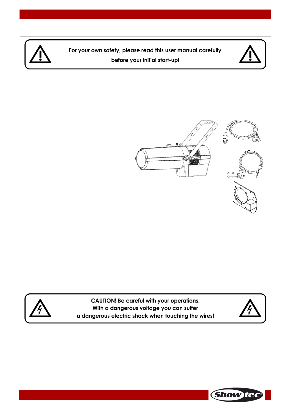
Your shipment includes:
● Showtec Performer Profile IP Q4
● Gobo holder with a glass gobo
● True1 to Schuko pro power cable (2,1 m)
● 2 x safety cable
● User manual
LED Expected Lifespan
LEDs gradually decline in brightness over time. HEAT is the dominant factor that leads to the acceleration
of this decline. Packaged in clusters, LEDs exhibit higher operating temperatures than in ideal or singular
optimum conditions. For this reason, when all color LEDs are used at their fullest intensity, life of the LEDs is
significantly reduced. If improving the lifespan is of higher priority, place care in providing for lower
operational temperatures. This may include climatic-environmental and the reduction of overall
projection intensity.
Safety Instructions
Every person involved with the installation, operation and maintenance of this device has to:
● be qualified
● follow the instructions of this manual
Before the initial start-up, please make sure that there is no damage caused by transportation.
Should there be any, consult your dealer and do not use the device.
To maintain perfect condition and to ensure a safe operation, it is absolutely necessary for the user to
follow the safety instructions and warning notes contained in this manual.
Please consider that damages caused by manual modifications to the device are not subject to
warranty.
This device contains no user-serviceable parts. Refer servicing to qualified technicians only.

3
Order code: 33111
Performer Profile IP Q4
IMPORTANT:
The manufacturer will not accept liability for any resulting damages caused by the non-observance of
this manual or any unauthorized modification to the device.
● Never let the power cord come into contact with other cables! Handle the power cord and all
connections with the mains with particular caution!
● Never modify, bend, mechanically strain, put pressure on, pull or heat up the power cord.
● Never strain the cable. There must always be sufficient cable going to the device. Otherwise, the
cable will be damaged, which can cause serious damage.
● Never remove warning or informative labels from the unit.
● Never use anything to cover the ground contact.
● Never lift the fixture holding it by the projector-head, as the mechanics may be damaged. Always
hold the fixture by the transport handles.
● Never place any material over the LEDs or the lens.
● Never look directly into the light source.
● Never leave any cables lying around.
● Never use the device during thunderstorms, unplug the device immediately.
● Never leave various parts of the packaging (plastic bags, polystyrene foam, nails, etc.) within
children’s reach, as they are potential sources of danger.
● Do not insert objects into air vents.
● Do not connect this device to a dimmer pack.
● Do not switch the device on and off in short intervals, as this will reduce the device’s life.
● Do not touch the device’s housing bare-handed during its operation (housing becomes very hot).
Allow the fixture to cool for at least 5 minutes before handling.
● Do not shake the device. Avoid brute force when installing or operating the device.
● Only operate the fixture after having checked if the housing is firmly closed and all screws are tightly
fastened.
● Only operate the device after having familiarized with its functions.
● Avoid flames and do not put close to flammable liquids or gases.
● Always keep the case closed while operating.
● Always allow a free air space of at least 50 cm around the unit for ventilation.
● Always disconnect power from the mains, when device is not used or before cleaning! Only handle
the power cord holding it by the plug. Never pull out the plug by tugging the power cord.
● Make sure that the device is not exposed to extreme heat, moisture or dust.
● Make sure that the available voltage is not higher than stated on the rear panel.
● Make sure that the power cord is never crimped or damaged. Check the device and the power
cord from time to time.
● If the lens is obviously damaged, it has to be replaced to prevent its functions from being impaired,
due to cracks or deep scratches.
● If the external cable is damaged, it has to be replaced by a qualified technician.
● If device was dropped or struck, disconnect mains power supply immediately. Have a qualified
engineer inspect for safety before operating.
● If the device has been exposed to drastic temperature fluctuation (e.g. after transportation), do not
switch it on immediately. The arising condensation water might damage your device. Leave the
device switched off until it has reached room temperature.
● If your Showtec device fails to work properly, discontinue the use immediately. Pack the unit securely
(preferably in the original packing material), and return it to your Showtec dealer for service.
● For adult use only. The device must be installed beyond the reach of children. Never leave the unit
running unattended.
● Never attempt to bypass the thermostatic switch or fuses.
● For replacement use fuses of same type and rating only.
● The user is responsible for correct positioning and operating of the Performer. The manufacturer will
not accept liability for damages caused by the misuse or incorrect installation of this device.
● This device falls under protection class I. Therefore it is essential to connect the yellow/green
conductor to earth.
● Repairs, servicing and electric connection must be carried out by a qualified technician.
● WARRANTY: Till one year after date of purchase.

4
Order code: 33111
Performer Profile IP Q4
Operating Determinations
● This device is not designed for permanent operation. Consistent operation breaks will ensure that the
device will serve you for a long time without defects.
● The minimum distance between light output and the illuminated surface must be bigger than
0,8 meter.
● In order to eliminate wear and improve the device’s lifespan, during periods of non-use, completely
disconnect from power source via breaker or by unplugging.
● The maximum ambient temperature t
a
= 40 °C must never be exceeded.
● The relative humidity must not exceed 50 % with an ambient temperature of 40 °C.
● If this device is operated in any other way than the one described in this manual, the product may
suffer damages and the warranty becomes void.
● Any other operation may lead to dangers like short-circuit, burns, electric shock, crash, etc.
You endanger your own safety and the safety of others!
Rigging
Please follow the European and national guidelines concerning rigging, trussing and all
other safety issues.
Do not attempt the installation yourself !
Always let the installation be carried out by an authorized dealer !
Procedure:
● If the Performer is lowered from the ceiling or high joists, professional trussing systems have to be used.
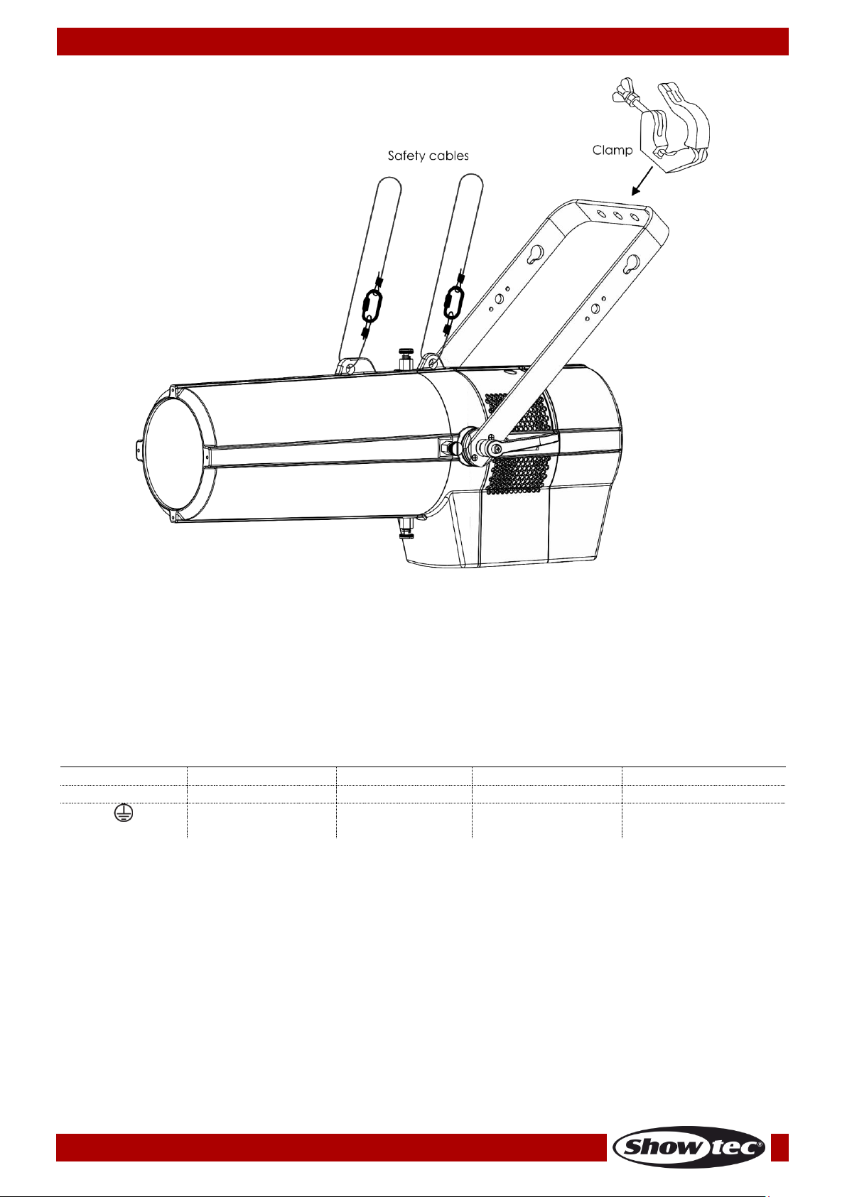
● Use a clamp to mount the Performer, with the mounting bracket, to the trussing system.
● The Performer must never be fixed swinging freely in the room.
● The installation must always be secured with a safety attachment, e.g. an appropriate safety net or
safety cable.
● When rigging, derigging or servicing the device, always make sure, that the area below the
installation site is secured and that there are not any unauthorized people around.
Improper installation can cause serious injuries and/or damage of property!
5
Order code: 33111
Performer Profile IP Q4
The Performer can be mounted to any kind of truss with a clamp.
Improper installation can cause serious injuries and/or damage of property!
Connection with the mains
Connect the device to the mains with the power-plug.
Always check if the right color cable is connected to the right place.
International
EU Cable
UK Cable
US Cable
Pin
L
BROWN
RED
YELLOW/COPPER
PHASE
N
BLUE
BLACK
SILVER
NEUTRAL
YELLOW/GREEN
GREEN
GREEN
PROTECTIVE
GROUND
Make sure that the device is always properly connected to the earth!
Improper installation can cause serious injuries and/or damage of property!

6
Order code: 33111
Performer Profile IP Q4
Return Procedure
Returned merchandise must be sent prepaid and in the original packing, call tags will not be issued.
Package must be clearly labeled with a Return Authorization Number (RMA number). Products returned
without an RMA number will be refused. Highlite will not accept the returned goods or any responsibility.
Call Highlite 0031-455667723 or mail aftersales@highlite.com and request an RMA prior to shipping the
fixture. Be prepared to provide the model number, serial number and a brief description of the cause for
the return. Be sure to properly pack fixture, any shipping damage resulting from inadequate packaging is
the customer’s responsibility. Highlite reserves the right to use its own discretion to repair or replace
product(s). As a suggestion, proper UPS packing or double-boxing is always a safe method to use.
Note: If you are given an RMA number, please include the following information on a piece of paper
inside the box:
01) Your name
02) Your address
03) Your phone number
04) A brief description of the symptoms
Claims
The client has the obligation to check the delivered goods immediately upon delivery for any shortcomings and/or visible defects, or perform this check after our announcement that the goods are at their
disposal. Damage incurred in shipping is the responsibility of the shipper; therefore the damage must be
reported to the carrier upon receipt of merchandise.
It is the customer's responsibility to report and submit claims with the shipper in the event that a fixture is
damaged due to shipping. Transportation damage has to be reported to us within one day after receipt
of the delivery.
Any return shipment has to be made post-paid at all times. Return shipments must be accompanied with
a letter defining the reason for return shipment. Non-prepaid return shipments will be refused, unless
agreed otherwise in writing.
Complaints against us must be prepared in writing or sent by fax within 10 working days after receipt of
the invoice. After this period complaints will not be handled anymore.
Complaints will only then be considered if the client has so far complied with all parts of the agreement,
regardless of the agreement from which the obligation is resulting.
7
Order code: 33111
Performer Profile IP Q4
Description of the device
Features
The Showtec Performer Profile IP Q4 is an IP-rated theater spotlight fixture with high output and great
effects.
● Input voltage: 110–240 V AC, 50/60 Hz
● Power consumption: 300W@FO
● Light source: 1 x 250W LED Array RGBW
● Drive current: 1,2A
● Light output: 9975 lx @ 3 m (15º)
● DMX Channels: HSIC (8CH), Simple (9CH), Colour 8Bit (12CH), Colour 16Bit (17CH)
● Control: Static, Manual, Master/Slave, DMX-512/RDM
● Refresh rate: 600 Hz–25 kHz
● CCT: 2700-8000K
● Dimmer: 0–100 %
● Strobe: 0–25 Hz
● Dimming curves: Dimm4 technology, 4 presets
● Dimming resolution: 16 bit
● Beam angle: 15º–30º
● Zoom: Electrical
● Focus: Electrical
● Gobo (included): 66 mm/49,5 mm (M size)
● Connections: Dedicated IP True1 pro power connector IN, IP 3-pin XLR signal connectors IN/OUT
● Housing: Die-cast aluminum
● Cooling: Fan
● Color: Black, powder-coated
● IP rating: IP65
● Dimensions: 650 x 340 x 575 mm (LxWxH)
● Weight: 13,74 kg
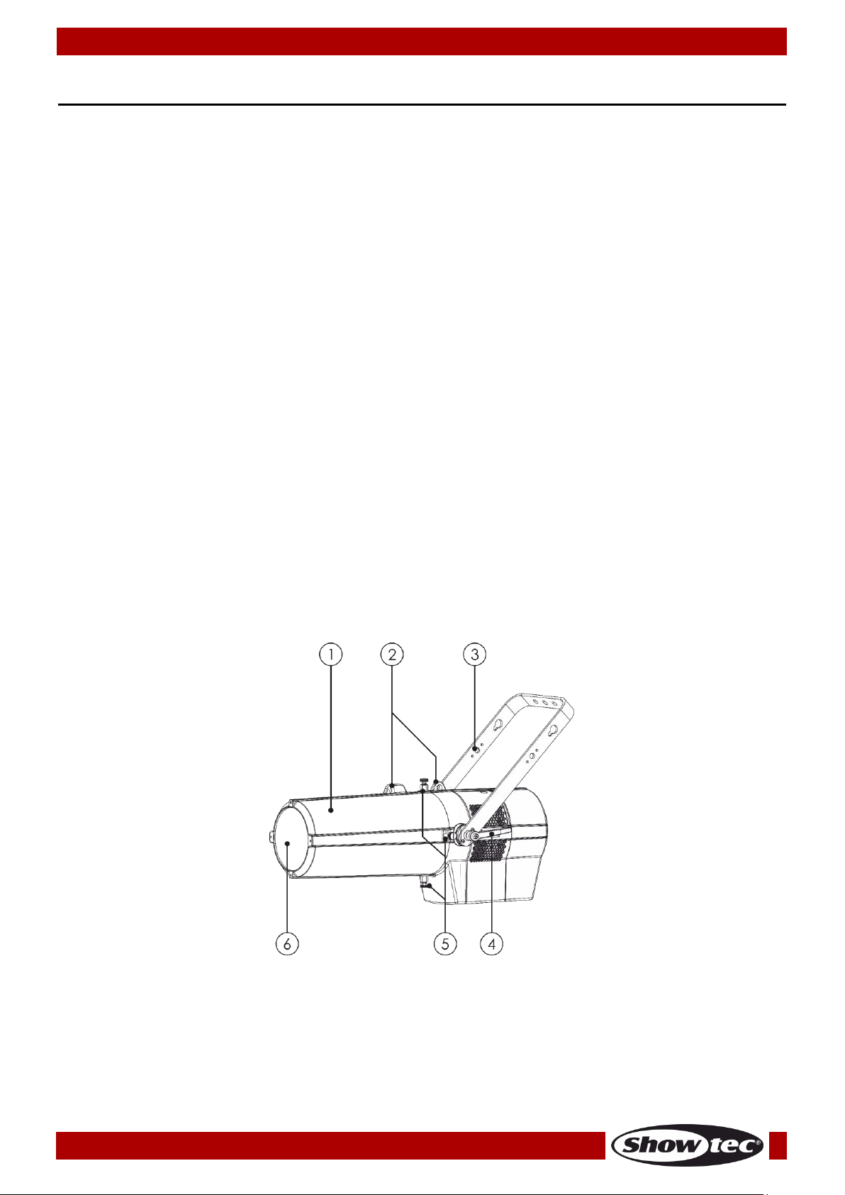
Overview
Fig. 01
01) Lens tube cover
02) Safety eyes
03) Mounting bracket
04) Adjustment screw
05) Lens tube cover mounting screws
06) Lens
8
Order code: 33111
Performer Profile IP Q4
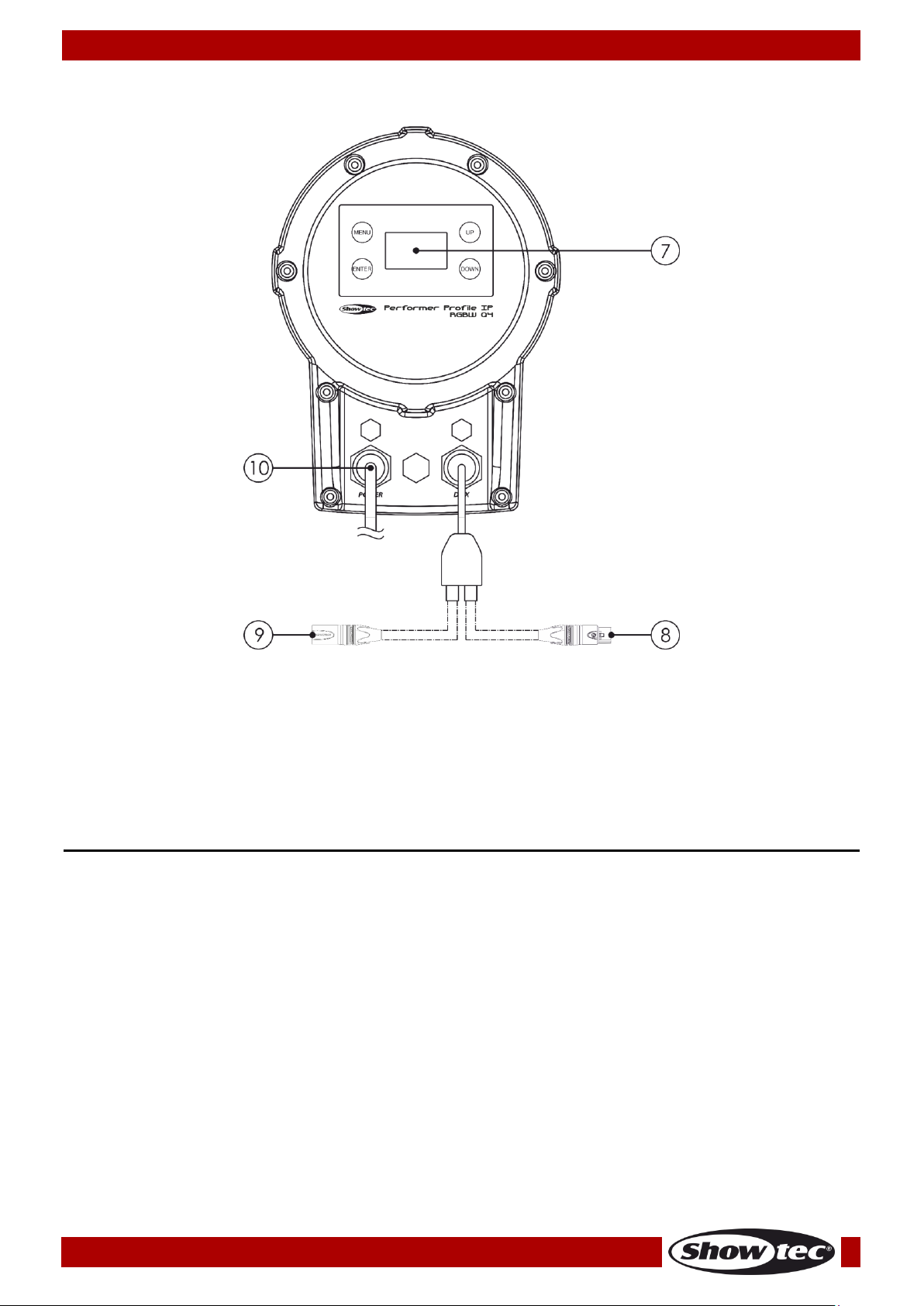
Backside
Fig. 02
07) OLED display + control buttons
08) 3-pin DMX signal connector OUT
09) 3-pin DMX signal connector IN
10) 100–240 V True1 pro power connector IN
Connect the included True1 pro power cable.
Installation
Remove all packing materials from the Performer Profile IP Q4. Check if all foam and plastic padding is
removed. Connect all cables.
Do not supply power before the whole system is set up and connected properly.
Always disconnect from electric mains power supply before cleaning or servicing.
Damages caused by non-observance are not subject to warranty.
9
Order code: 33111
Performer Profile IP Q4
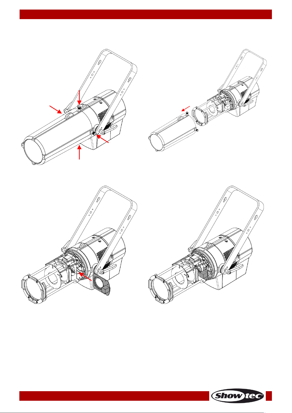
Gobo Holder Installation
01) Loosen the 4 cover mounting screws (Fig. 03) and remove the cover (Fig. 04).
Fig. 03
Fig. 04
02) Slide the gobo holder into the slot (Fig. 05) until it is locked in position (Fig. 06).
Fig. 05
Fig. 06
03) Connect the cable on the gobo with the connector on the Performer.
04) Replace the cover and tighten the 4 mounting screws.
10
Order code: 33111
Performer Profile IP Q4
Setup and Operation
Follow the directions below, as they pertain to your preferred operation mode.
Before plugging the unit in, always make sure that the power supply matches the product specification
voltage. Do not attempt to operate a 120 V specification product on 230 V power, or vice versa.
Connect the device to the main power supply.
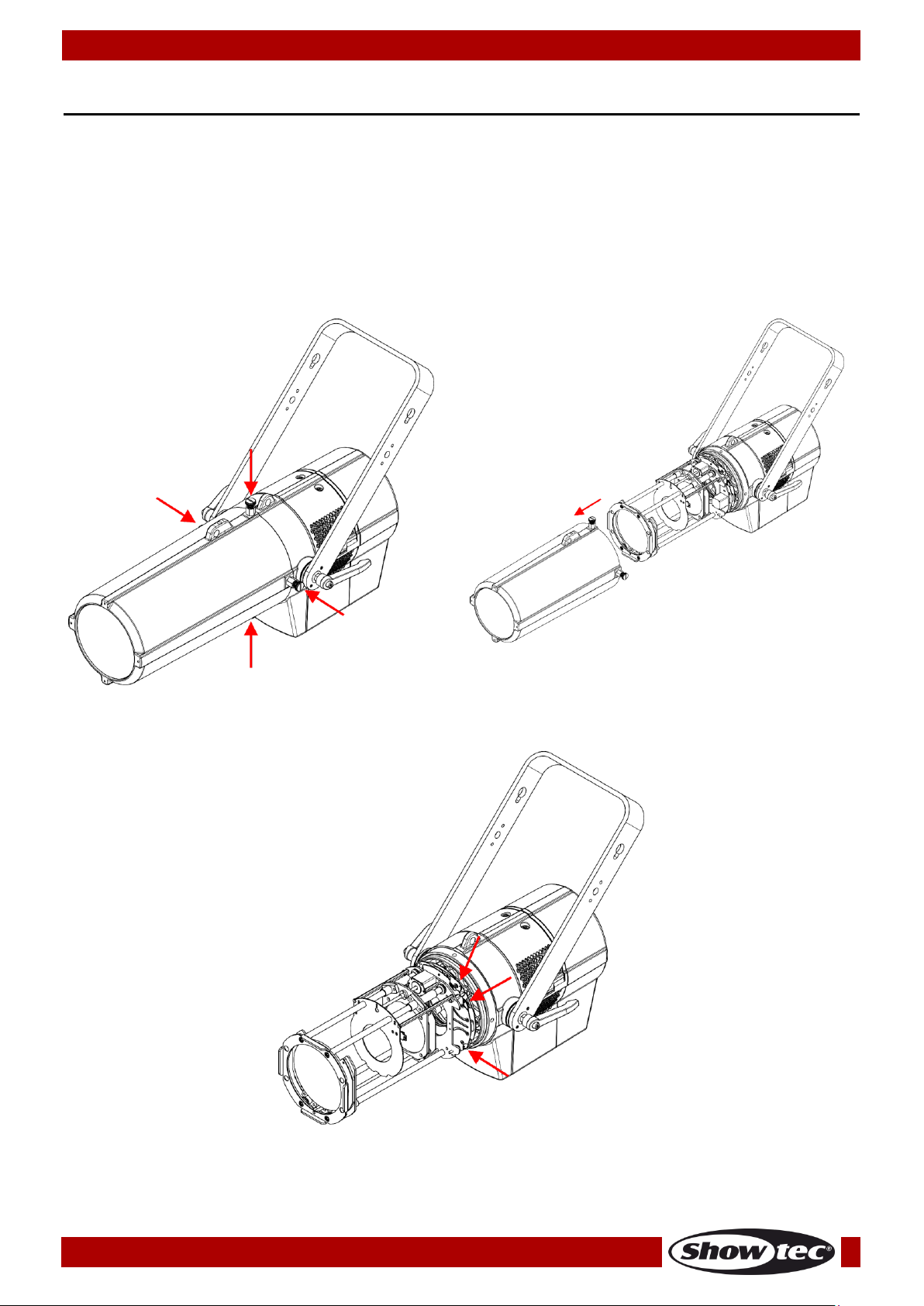
Shaping the Beam
The shutters are located inside the barrel. Turn the shutter controls to move the shutters back and forth to
modify the shape of the beam.
01) Loosen the 4 cover mounting screws (Fig. 07) and remove the cover (Fig. 08).
Fig. 07
Fig. 08
02) Move the shutter controls to position the shutters (Fig. 09). There are 6 shutter controls (2 per shutter).
Fig. 09
03) Replace the cover and tighten the 4 mounting screws.
11
Order code: 33111
Performer Profile IP Q4
Control Modes
There are 4 modes:
● Static
● Manual (Custom Programs)
● Master/Slave
● DMX-512/RDM (8CH, 9CH, 12CH, 17CH)
One Performer (Static, Manual)
01) Fasten the effect light to a firm trussing. Leave at least 0,5 meter on all sides for air circulation.
02) Always use a safety cable (ordercode 70140 / 70141).
03) Plug the end of the electric mains power cord into a proper electric power supply socket.
04) When the Phantom is not connected with a DMX cable, it functions as a stand-alone device.
Please see pages 17–19 for more information about Static and Manual mode.
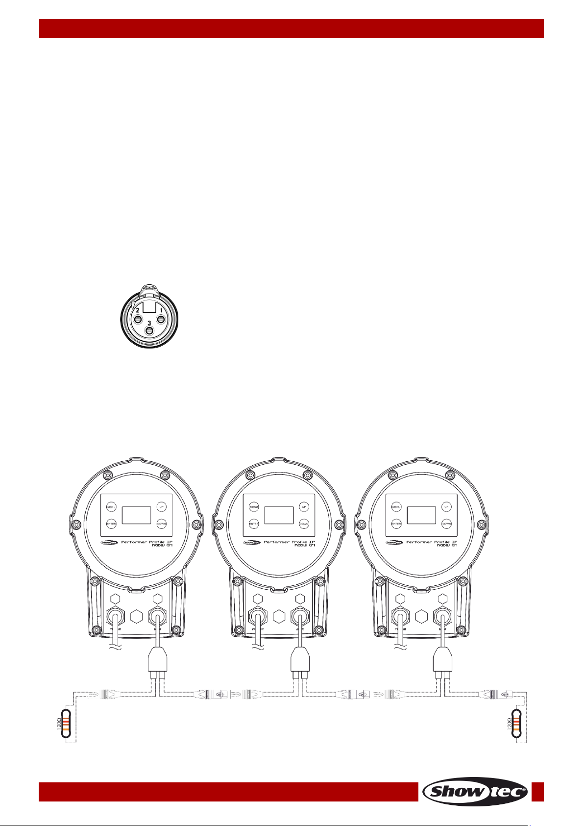
Multiple Performers (Master/Slave control)
01) Fasten the effect light onto firm trussing. Leave at least 0,5 meter on all sides for air circulation.
02) Always use a safety cable (ordercode 70140 / 70141).
03) Use a 3-pin XLR cable to connect the Performer.
The pins:
01) Earth
02) Signal -
03) Signal +
04) Link the units as shown in Fig. 10. Connect the first unit's DMX "out" socket with the second unit's "in"
socket, using a DMX signal cable. Repeat this process to link the second, third and fourth units.
You can use the same functions on the master device as described on pages 17–19 (Static or
Manual mode). This means that you can set your desired operation mode on the master device
and all slave devices will react the same as the master device.
Multiple Performers (Master/Slave control)
Fig. 10
 Loading...