

Page 1
Arc-Bar 3
ORDERCODE 41350
Page 2

Congratulations!
You have bought a great, innovative product from Showtec.
The Showtec Arc-Bar 3 brings excitement to any venue. Whether you want simple plug-&-play action or a
sophisticated DMX show, this product provides the effect you need.
You can rely on Showtec, for more excellent lighting products.
We design and manufacture professional light equipment for the entertainment industry.
New products are being launched regularly. We work hard to keep you, our customer, satisfied.
For more information: iwant@showtec.info
You can get some of the best quality, best priced products on the market from Showtec.
So next time, turn to Showtec for more great lighting equipment.
Always get the best -- with Showtec !
Thank you!
Page 3

1
2
2
2
3
4
5
6
7
7
7
8
8
9
9
9
9
10
11
12
13
14
15
16
16
17
17
17
18
19
19
20
22
23
24
25
25
26
27
28
28
28
29
Showtec
Showtec Arc-Bar 3™ Product Guide
Warning..…...................................................................................…………………………………….………….…….
Unpacking Instructions………………………………………………………………………………………………….
Contact Us…………………………………………………………………………………………………………….…..
Safety-instructions………………………………………………………………………………………………………..
Operating Determinations…………………………………………………………………………………………….
Rigging………………………………………………………………………………………………………………….…
Interlocking Multiple Fixtures………………………………………………………………………….………………
Description..…..............................................................................……….…………………………………………….
Features…….……………………………………………………………………………………….……...……………..
DMX Channel Summary………………………………………………………………………………………………..
Overview…………………………………………………………………………………………………………………..
Backside…………………………………………………………………………………………………………………...
Installation...............................................................................…...…………………………………….…………….…
Set Up and Operation.....................................................................……..…………………………….………………
Fixture Linking…………………............……..……………………………………………..……………………………
Data Cabling…………………............……..……………………………………………..……………………………
DMX Addressing without ID addressing.……………………............……..……………………………………….
DMX Addressing with ID Address……….........………………………………………....……………………………
ADAS with ID address...........……..…………....……..………………......……..…………………………………….
Control Panel...........……..…………....……..………………......……..……………………………………………...
MENU OVERVIEW ……..……………………………………..…………………………………….…….…………...…
- Creating a static color …...............................................…......……………………....…………..………..
- DMX 512 Address......................................................................….....……………..………………………..
- Activating an Auto Program …...............................................………………….....………………………
- Changing the Settings...............................................................….....……………..……………...……….
- Activating the Password …...............................................…......……………………....…………………..
- Power ON/OFF.................................…......……………………....…………………………………………….
Menu Map.....................................……..…………………………….......……..…………………………………..…..…
DMX Protocol.....................................……..…………………………….......……..…………………………………..…
Basic Instructions for DMX512 Operation DMX Mode 1...................................……..…………………………
DMX Control Mode 1..............……..….………………......………………....………………………………….……
Basic Instructions for DMX512 Operation DMX Mode 2...................................……..…………………………
DMX Control Mode 2..............……..….………………………………………………………………………………
DMX Value – ID Addresses......................................……..…………………………….………………………………
Examples.………………...................................................................……..…………………………….………………
Example 1..............……..………………………………………………………………………………………………..
Example 2..............……..………………………………………………………………………………………………..
Beam Angles…………...................................................................……..…………………………….………………..
Connection Cables.….................................................................……..…………………………….………………..
Maintenance...................................................................................………..………….…….………………………..
Troubleshooting............................................................................………………….………………….………………
Product Specifications.................................................................……………….…….………………………………
Page 4

2
WARNING
FOR YOUR OWN SAFETY, PLEASE READ THIS USER MANUAL CAREFULLY
BEFORE YOUR INITIAL START-UP!
Unpacking Instructions
Immediately upon receiving this product, carefully unpack the carton and check the contents to ensure
that all parts are present, and have been received in good condition. Notify the dealer immediately and
retain packing material for inspection if any parts appear damaged from shipping or the carton itself
shows signs of mishandling. Save the carton and all packing materials. In the event that a fixture must be
returned to the factory, it is important that the fixture be returned in the original factory box and packing.
Your shipment includes:
• Arc-Bar 3
• 1X Powercable
• 1X XLR to 3-pin special connection cable
• User manual
Contact Us
General Information Highlite International B.V..
Vestastraat 2
6468 EX Kerkrade
The Netherlands
Sales Department: 0031 45-5667701
Export Department: 0031 45-5667706
Technical Support Highlite International B.V..
Vestastraat 2
6468 EX Kerkrade
The Netherlands
Technical Department: 0031 45-5667703
Internet www.highlite.nl/
LED Expected Lifespan
LEDs gradually decline in brightness over time. HEAT is the dominant factor that leads to the acceleration
of this decline. Packaged in clusters, LEDs exhibit higher operating temperatures than in ideal or singular
optimum conditions. For this reason when all color LEDs are used at their fullest intensity, life of the LEDs is
significantly reduced. It is estimated that a viable lifespan of 40,000 to 50,000 hours will be achieved
under normal operational conditions. If improving on this lifespan expectancy is of a higher priority, place
care in providing for lower operational temperatures. This may include climatic-environmental and the
reduction of overall projection intensity.
Page 5
3
SAFETY INSTRUCTIONS
CAUTION! Be careful with your operations.
With a dangerous voltage you can suffer
a dangerous electric shock when touching the wires!
Every person involved with the installation, operation and maintenance of this device has to:
- be qualified
- follow the instructions of this manual
Before your initial start-up, please make sure that there is no damage caused by transportation. Should
there be any, consult your dealer and do not use the device.
To maintain perfect condition and to ensure a safe operation, it is absolutely necessary for the user to
follow the safety instructions and warning notes written in this manual.
Please consider that damages caused by manual modifications to the device are not subject to
warranty.
This device contains no user-serviceable parts. Refer servicing to qualified technicians only.
IMPORTANT:
The manufacturer will not accept liability for any resulting damages caused by the nonobservance of this manual or any unauthorized modification to the device.
Never let the power-cord come into contact with other cables! Handle the power-cord and all
connections with the mains with particular caution!
Never remove warning or informative labels from the unit.
Never use anything to cover the ground contact.
Never look directly into the light source.
Never leave any cables lying around.
Never use the device during thunderstorms, unplug the device immediately.
Never leave various parts of the packaging (plastic bags, polystyrene foam, nails, etc.) within
children’s reach, as they are potential sources of danger.
Do not insert objects into air vents.
Do not open the device and do not modify the device.
Do not connect this device to a dimmerpack.
Do not shake the device. Avoid brute force when installing or operating the device.
Do not switch the device on and off in short intervals, as this would reduce the system’s life.
Only use device indoor, avoid contact with water or other liquids.
Only operate the device after having familiarized with its functions.
Avoid flames and do not put close to flammable liquids or gases.
Always allow free air space of at least 50 cm around the unit for ventilation.
Always disconnect power from the mains, when device is not used or before cleaning! Only
handle the power-cord by the plug. Never pull out the plug by tugging the power-cord.
Make sure that the device is not exposed to extreme heat, moisture or dust.
Make sure that the available voltage is not higher than stated on the rear panel.
Make sure that the power-cord is never crimped or damaged. Check the device and the power-
cord from time to time.
Make sure that no side forces can impact on the truss system.
The cable insert or the female part in the device must never be strained. There must always be
sufficient cable to the device. Otherwise, the cable may be damaged which may lead to deadly
electrical shocks.
If the external cable is damaged, it has to be replaced by a qualified technician.
If the lens is obviously damaged, it has to be replaced. So that its functions are not impaired, due
to cracks or deep scratches.
If device is dropped or struck, disconnect mains power supply immediately. Have a qualified
engineer inspect for safety before operating.
Page 6
4
If the device has been exposed to drastic temperature fluctuation (e.g. after transportation), do
CAUTION ! EYEDAMAGES !.
Avoid looking directly into the light source.
(meant especially for epileptics) !
not switch it on immediately. The arising condensation water might damage your device. Leave
the device switched off until it has reached room temperature.
If your Showtec device fails to work properly, discontinue use immediately. Pack the unit securely
(preferably in the original packing material), and return it to your Showtec dealer for service.
For adult use only. The device must be installed out of the reach of children. Never leave the unit
running unattended.
For replacement use fuses of same type and rating only.
The user is responsible for correct positioning and operating of the Arc-Bar 3. The manufacturer will
not accept liability for damages caused by the misuse or incorrect installation of this device.
This device falls under protection class I. Therefore it is essential to connect the yellow/green
conductor to earth.
Repairs, servicing and electric connection must be carried out by a qualified technician.
WARRANTY: Till one year after date of purchase.
OPERATING DETERMINATIONS
This device is not designed for permanent operation. Consistent operation breaks will ensure that the
device will serve you for a long time without defects.
The minimum distance between light-output and the illuminated surface must be more than 1.5 meter.
The maximum ambient temperature ta = 45°C must never be exceeded.
The relative humidity must not exceed 50 % with an ambient temperature of 45° C.
If this device is operated in any other way, than the one described in this manual, the product may suffer
damages and the warranty becomes void.
Any other operation may lead to dangers like short-circuit, burns, electric shock, lamp explosion, crash
etc.
You endanger your own safety and the safety of others!
Improper installation can cause serious damage to people and property !
Page 7

5
Rigging
Please follow the European and national guidelines concerning rigging, trussing and all other
safety issues.
Do not attempt the installation yourself !
Always let the installation be carried out by an authorized dealer !
Procedure:
If the Arc-Bar is lowered from the ceiling or high joists, professional trussing systems have to be
used.
Use a clamp to mount the Arc-Bar, with the mounting-bracket, to the trussing system.
The Arc-Bar must never be fixed swinging freely in the room.
The installation must always be secured with a safety attachment, e.g. an appropriate safety net
or safety-cable.
When rigging, derigging or servicing the Arc-Bar, always make sure, that the area below the
installation place is blocked and staying in the area is forbidden.
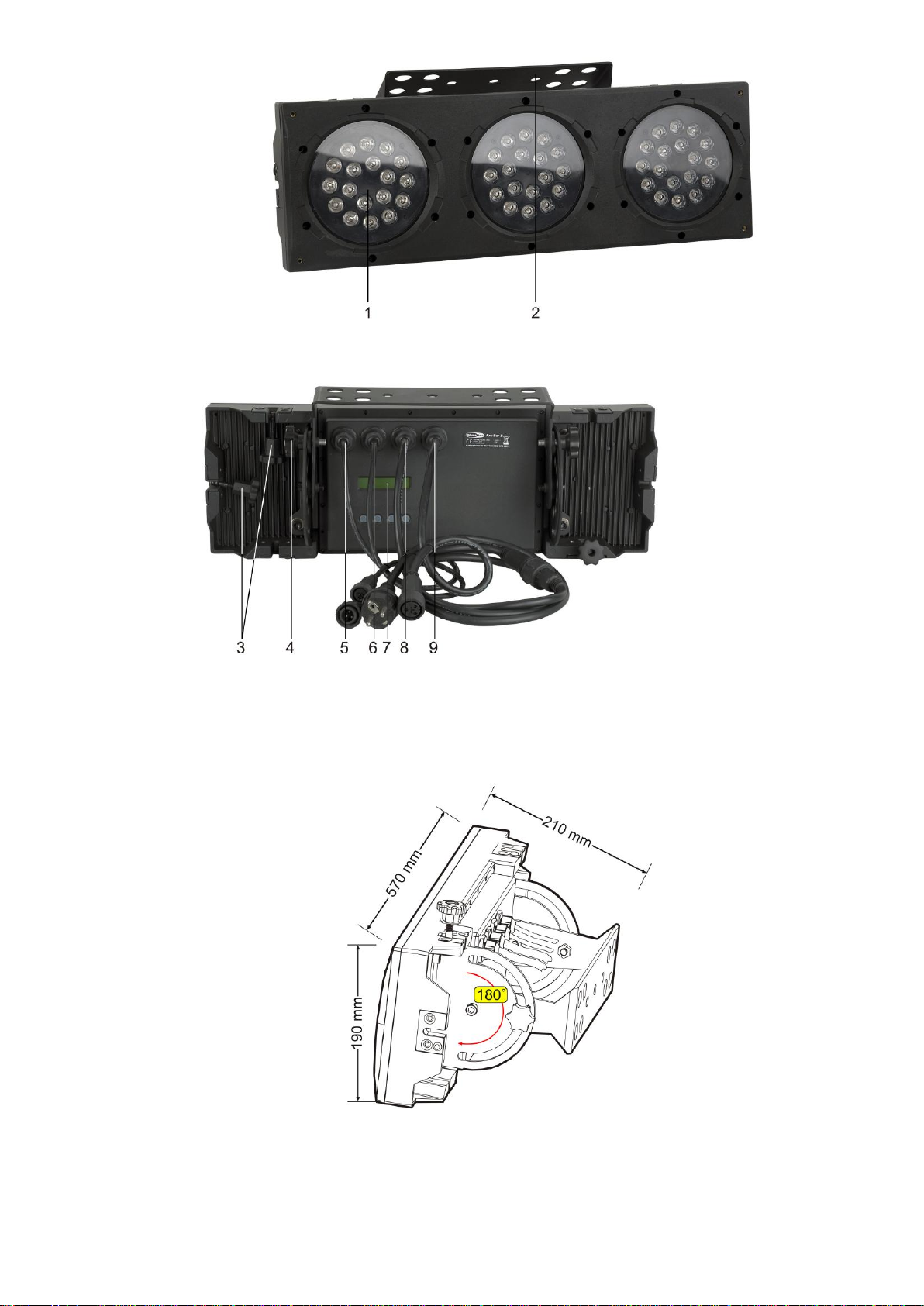
The Arc-Bar 3 can be mounted in a hanging position (Fig. Above) or Upright (Fig. Below), using the
support frame. It is recommended to use at least 2 mounting points per fixture. Mounting the Arc-Bar with
a clamp or any other mounting bracket is recommended, depending on the requirements of your
application.
The Arc-Bar 3 can be placed on a flat stage floor or mounted to any kind of truss by a clamp.
Improper installation can cause serious damage to people and property !
Page 8
6
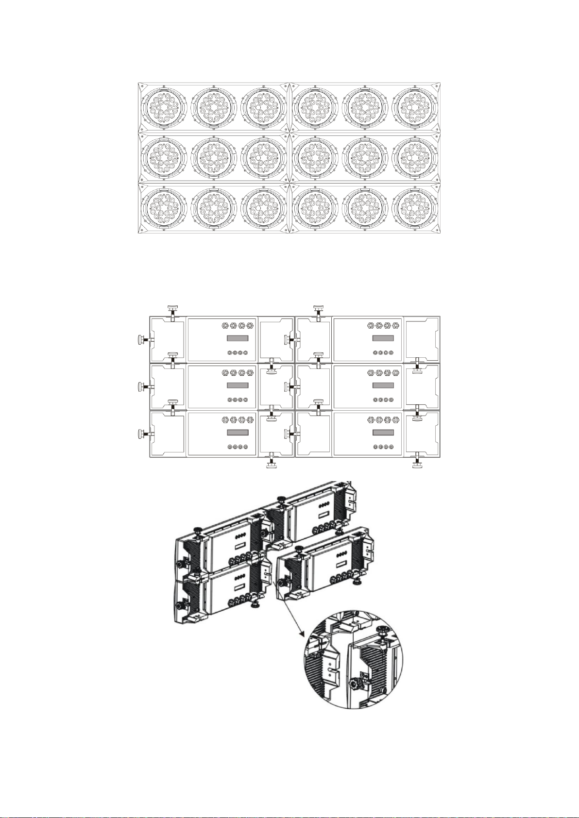
Interlocking Multiple Fixtures
The figure below shows how multiple units can be interlocked together to create a 'panel' or 'blinder'
arrangement.
The 'male' and 'female' connections enable the fixtures to be interlocked together in the way shown in
the figure below.
Note: When multiple units are mounted together, it is not necessary to attach every single unit to the truss,
wall or weight supporting system. However, it is important to ensure that all fixtures are securely locked
together and that each fixture is individually secured using a safety cable.
Page 9
7
Description of the device
DMX Mode 1
Channel
Description
1 Red 2
Green 3
Blue 4
Yellow 5
Cyan 6
Purple 7
White 8
Strobe 9
Mode selection 245 <>255 : DMX Mode 2
10
ID Address selection
11
Module selection
12
Effect macro
DMX Mode 2
Channel
Description
1 Module #1
2 Module #2
3 Module #3
4 No Function
5 No Function
6 No Function
7 No Function
8 Strobe 9
Mode selection 000 <>244 : DMX Mode 1
10
ID Address selection
11
No Function
12
No Function
Features
The Arc-Bar 3 is a LED system from Showtec.
• IP rating: IP-65
• Output/LED: 1W
• Total LEDs: 54 (18x Red, 18x Green, 18x Blue)
• 12-channel DMX-512 LED bank system
• Separate DMX channels for red, green, blue, cyan, magenta, yellow and whi te
• Blackout/static/dimmer/strobe
• Separate RGB control over each individual pod
• RGB color mixing with or without DMX controller
• Flip-down knobs for interlocking multiple units together, which can create blinder, wall and strip
light
effects (flush mounted)
• Automatic DMX-512 addressing (ADAS)
• LED display with lock-out feature
• Black anti-UV plastic cover
• Low power consumption
• Cooling: Direct air convection
• Beam Angle: 30 degrees
• Control: DMX-512 with 12 channels (with ID addressing)
• Effects: RGB Color mixing, Auto-programs, Strobe, Dimmer, Automatic DMX Addressing,
Intelligent ID addressing
NOTE: Knowledge of DMX is required to fully utilize this unit.
DMX Channel Summary
Page 10
8
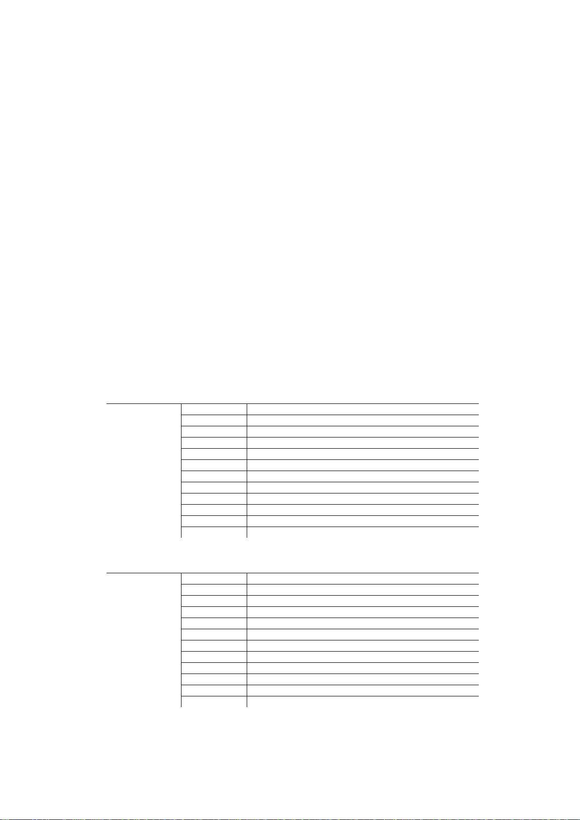
Overview
Fig. 1
1) 3x18 LEDS; Total 54 LEDs
2) Mountingbracket for Truss mounting
Backside
Fig. 2
3) Screws for connecting device side by side and/or on top of eachother
4) Adjustment Screw
5) DMX signal connector (IN)
6) DMX signal connector (OUT)
7) Power IN
8) Power OUT
9) LCD Display + Nenu Buttons (Set / Up / Down / Ext)
Page 11

9
Installation
Remove all packing materials from the Arc-Bar 3. Check that all foam and plastic padding is removed.
Connect all cables.
Do not supply power before the whole system is set up and connected properly.
Always disconnect from electric mains power supply before cleaning or servicing.
Damages caused by non-observance are not subject to warranty.
Set Up and Operation
Before plugging the unit in, always make sure that the power supply matches the product specification
voltage. Do not attempt to operate a 120V specification product on 230V power, or vice versa.
Fixture Linking
You will need a serial data link to run light shows of one or more fixtures using a DMX-512 controller or to
run synchronized shows on two or more fixtures set to a master/slave operating mode. The combined
number of channels required by all the fixtures on a serial data link determines the number of fixtures the
data link can support.
The Arc-Bar 3 uses 12 channels.
Important: Fixtures on a serial data link must be daisy chained in one single line. To comply with the
EIA-485 standard no more than 32 devices should be connected on one data link.
Connecting more than 32 fixtures on one serial data link without the use of a DMX optically
isolated splitter may result in deterioration of the digital DMX signal.
Maximum recommended serial data link distance: 500 meters
Maximum recommended number of Arc-Bars on a serial data link: 32 fixtures
Data Cabling
To link fixtures together you must obtain data cables. You can purchase DAP Audio certified DMX cables
directly from a dealer/distributor or construct your own cable. If you choose to create your own cable
please use data-grade cables that can carry a high quality signal and are less prone to electromagnetic
interference.
DAP Audio Certified DMX Data Cables
• DAP Audio Basic microphone cable for allround use. bal. XLR/M 3 p. > XLR/F 3 p.
Ordercode FL01150 (1,5m.), FL013 (3m.), FL016 (6m.), FL0110 (10m.), FL0115 (15m.), FL0120 (20m.).
• DAP Audio cable for the demanding user with exceptional audio-qualities and connector made by
Neutrik®. Ordercode FL71150 (1,5m.), FL713 (3m.), FL716 (6m.), FL7110 (10m.).
Page 12

10
DMX512 ADDRESSING WITHOUT ID ADDRESSING
1) Connect a DMX controller (example 50403 Showdesigner) to the series of Arc-Bars.
2) Each Arc-Bar has 12 DMX channels (DMX address Arc-Bar #1=1, Bar #2=13, Bar #3=25, Bar #4=37,
etc.).
3) The ID address has not been set, so therefore when using the controller CH10 must be inactive (
CH10=0 ). It is also possible to deactivate the ID address, by selecting ID OFF from the Settings menu.
4) Any DMX address in the range from 001 to 244 may be used.
Showdesigner (50403)
Note: When using the Arc-Bars, the CH10 ID function must be inactive (CH10=0).
Page 13

11
DMX512 ADDRESSING WITH ID ADDRESS
1) Connect a DMX controller (example 50403 Showdesigner) to the series of Arc-Bars.
2) Each Arc-Bar has 12 DMX channels (DMX address Arc-Bar #1=1, Bar #2=13, Bar #3=25, Bar #4=37,
etc.).
3) Any DMX address in the range from 001 to 244 may be used.
4) Each DMX address may carry up to 66 separate ID addresses.
5) The ID Address should be set in the SETTINGS menu, on each unit in ascending values (i.e. 1,2,3...).
6) ID On should be set in the SETTINGS menu on each unit.
7) ID addresses are accessible from CH10 on the DMX512 controller.
Showdesigner (50403)
The figure above shows a simple DMX layout. All the Arc-Bars have different ID addresses which allows
the user to collectively control the whole group of Arc-Bars with the same DMX address by setting CH10
to 0, or to control each Arc-Bar independently by first selecting the DMX address and then by using CH10
to locate the target ID address.
Note: When using ID addresses it is also possible to activate ADAS (=Automatic DMX Addressing system),
which allows for even more options with DMX addressing and control.
Page 14

12
ADAS WITH ID ADDRESS (Automatic DMX Addressing System)
1) Connect a DMX controller (example 50403 Showdesigner) to the series of Arc-Bars.
2) Select ADAS ON from the Settings menu.
3) The ID Address should be set in the SETTINGS menu, on each unit in ascending values (i.e. 1,2,3...).
4) ADAS addressing is based on the ID address as follows:
ADAS DMX Address = { ADAS fader * (ID Address -1)}+ 1.
5) ADAS addressing is activated by moving CH8 + CH10 faders to the 255 value (CH8 = 255 & CH10 =
255).
6) ADAS addressing is deactivated by moving CH8 + CH10 + CH11 to the 255 value (CH8 = 255, CH10 =
255 & CH11 = 255).
7) When ADAS is deactivated, all DMX addresses will return to their original DMX Address.
8) To permanently store ADAS DMX addresses, select ADAS copy from the Settings menu,on the target
fixtures to store the new DMX Address.
Showdesigner (50403)
The figure above shows a simple ID address layout with only using one DMX address. Each Arc-Bar has a
different ID address, which will receive a new temporary DMX address when ADAS is activated (unless
ADAS copy is selected). The user is able to activate and deactivate ADAS, thus giving the possibility of
creating many different fixture grouping possibilities using the ID address, real DMX address and the ADAS
temporary DMX address.
Note: When using ADAS, all fixtures must have the following settings from the SETTINGS menu:
ID address Each unit should have the target ID address set in ascending order.
ID ON/OFF Each unit should set ID On.
ADAS fader no Each unit should be set to the same number of faders as your controller (must be≥ 12).
ADAS ON/OFF Each unit should be set as ADAS On.
Page 15

13
Control Panel
Fig. 5
A. Display D. Down Button
B. [SET] Button E. EXIT Button
C. UP Button
Page 16

14
MENU OVERVIEW
Page 17

15
Press the UP/DOWN buttons to scroll through 5 options of the menu:
Creating a static color
When you press SET in menu Static color, you can use your colors or strobe.
When you press SET again (choosing RED), the display shows:
You can use the up/down buttons to select the percentage of Red (0-255).
Press EXiT to go 1 step back.
You can combine RED, GREEN and BLUE to create an infinite range of colors (0-255).
Alternatively you can select YELLOW, CYAN, PURPLE and WHITE with full control over the intensity (0-255).
Or you can set the value of the strobe (0-20Hz).
Red Cyan
Set the value of the red LEDs (0-255). Set the value of the cyan LEDs (0-255).
Green Purple
Set the value of the green LEDs (0-255). Set the value of the purple LEDs (0-255).
Blue White
Set the value of the blue LEDs (0-255). Set the value of the white LEDs (0-255).
Yellow Strobe
Set the value of the yellow LEDs (0-255). Set the value of the flash (0-20Hz).
Page 18

16
DMX 512 Address
When you press SET in menu DMX 512 address to set the DMX address.
You can choose your DMX address between 0-244.
Activating an Auto Program
When you press SET in menu Auto Program, you can choose one of the 8 built-in programs.
When you press SET again (choosing Auto), the display shows:
Page 19

17
Changing the Settings
When you press SET in menu settings, you can choose:
1) ID address [01-66]
2) ID ON/OFF ON [OFF]
3) ADAS fader no [000-512]
4) ADAS ON/OFF ON [OFF]
5) ADAS copy ON [OFF]
6) ADAS copy ON/OFF ON [OFF]
When you press SET again (choosing ID address), the display shows:
You can use the up/down buttons to select the ID address (0-66)
Ad 1) Enter the ID Address to set the ID address for the unit.
Ad 2) Enter ID ON/OFF in order to allow/disallow ID address function from the DMX512 controller.
Ad 3) Enter the ADAS fader no to set the number of channel faders in each layer of the controller.
Ad 4) In ADAS ON/OFF select allow/disallow Automatic DMX512 Addressing System (ADAS).
Ad 5) In the ADAS COPY menu select whether to allow copy of DMX address to unit after ADAS has
assigned new DMX address when ADAS function is activated from the DMX512 controller.
Ad 6) Enter the [Reset to Factory Settings] in order to reset to default factory settings.
Activating the Password
1) Enter the Password mode to set a password ON/OFF.
2) When the password is activated, the display will ask for password each time the fixture is powered on.
3) Enter the Set password menu to change password.
4) Set a new password using the UP & DOWN keys.
5) Input an 8 digit password and then press SET to confirm.
NOTE: In the event that the password is forgotten. Please use the factory password shown below.
UP > DOWN > UP > DOWN > UP > UP > DOWN > DOWN
Power ON/OFF
1) When the display shows MENU , hold down the EXIT button for 3 seconds to turn off power.
2) When display is off, hold down the EXIT button for 3 seconds to turn on power.
Page 20

18
Menu Map
Main Function
Sub-Function
Selection
Description
Red
Green
• User can combine Red, Green and Blue
Blue
000 – 255*
to generate a custom color
Static Color
Yellow
(0 – 100%)
• Select intensity over pre-composed
Cyan
colors yellow, cyan, purple and white
Purple
*strobe range
• Select strobing frequency between 0
White
Is 0 – 20
and 20Hz
Strobe
DMX address
001 – 244
• 244 addressable DMX channels
1
2
3
Auto Program
4
• Choose from 8 Automatic run programs
5
6
7
8
ID Address
01 – 66
Assigns the ID address to a fixture
ID ON/OFF
On – Off
Either enables or disables ID addressing
Settings
ADAS Faders no
001 – 244
Sets the number of ADAS channels for use
when automating DMX channel assignment
ADAS ON/OFF
On – Off
Enables the Automatic DMX512
Addressing System
ADAS Copy
On – Off
When activated the DMX512 address
assigned by the ADAS will become
permanent on the fixture
Factory Settings
Reset Confirm
Resets fixture to factory default settings
When password is set to on the control
ON/OFF
On – Off
panel will ask for a password each time the
Password
control panel is accessed
Use UP and DOWN buttons to set and
press SET to confirm
Set Password
[????????]
Note! If you forget the password use the
following factory password:
UP, DOWN, UP, DOWN, UP, UP, DOWN
,DOWN
Power
Description
Turn OFF
When MENU is displayed in the LCD panel, hold down the EXIT-button for
3 seconds to turn off the fixture
Turn ON
Hold the EXIT-button for 3 seconds to turn power on
Page 21

19
BASIC INSTRUCTIONS FOR DMX512 OPERATION
DMX MODE 1
RED, GREEN & BLUE COLOR SELECTION
• CH1, CH2 & CH3 control the intensity ratio of each of the RED, GREEN & BLUE LEDs.
• When the slider is at the highest position (255) the intensity of the color is the maximum.
• CH1, CH2 & CH3 can be combined together to create over 16 million colors.
• CH1, CH2, CH3 have priority over CH4, CH5, CH6 & CH7.
YELLOW, CYAN, PURPLE & WHITE
• CH4, CH5, CH6 & CH7 are independent colors and cannot be mixed with any other color control
channel.
• When multiple channels are used at the same time; lower channel number is priority (i.e. CH4 has
Priority over all channels 1-6).
STROBE
• Strobe occurs at every channel with exception to programs on Channel 9 and 12.
• The strobe is with an adjustable speed from 0 to 20 Hz.
• The strobe is not active with CH9 & CH12
MODE SELECTION
• CH9 allows the user to activate DMX MODE 1 or DMX MODE 2.
• CH9 values 5-244 can only be activated when CH1 to CH7 are not activated.
• When Color-Cycle Mode 4 is selected CH11 controls the speed of the Color-cycle.
ID ADDRESS SELECTION
• CH10 is used to select the target ID address.
• Each independent DMX address may have up to 66 independent ID addresses.
• An ID address of 0 will be activated by all ID address locations.
• ID address “0” allows control of all fixtures simultaneously.
MODULE SELECTION
• CH11 controls set combinations of the three LED MODULES present in each unit.
• CH11 has priority over CH12 when first activated.
EFFECT MACRO
• The effect MACRO channel allows the user to select from combinations of different colors and LED
modules in a quick-and-easy action.
• These are pre-programmed color patterns and module chases.
• CH12 has priority over color control channels (CH1, CH2, CH3, CH4, CH5, CH6 & CH7).
• CH12 has priority over CH11 when first activated.
• CH12 has priority over Ch9 & Ch11.
Page 22

20
DMX Control Mode 1
Channel
Value
Function
1
000 – 004
Red
No Function
005 – 255
0 – 100 % 2
000 – 004
Green
No Function
005 – 255
0 – 100 % 3
000 – 004
Blue
No Function
005 – 255
0 – 100 % 4
000 – 004
Yellow
No Function
005 – 255
0 – 100 % 5
000 – 004
Cyan
No Function
005 – 255
0 – 100 %
6
000 – 004
Purple
No Function
005 – 255
0 – 100 % 7
000 – 004
White
No Function
005 – 255
0 – 100 %
8
000 – 004
Strobe
No Function
005 – 255
0 – 20 Hz
000 – 004
Mode Selection
No Function
005 – 034
Color-Cycle Mode 1
035 – 064
Color-Cycle Mode 2
065 – 094
Color-Cycle Mode 3
9
095 – 124
Color-Cycle Mode 4
125 – 154
Color-Cycle Mode 5
155 – 184
Color-Cycle Mode 6
185 – 214
Color-Cycle Mode 7
215 – 244
Color-Cycle Mode 8
245 – 255
DMX Mode 2
Channel 10 (ID address selection)
000 – 009
All ID’s
212
ID 23
235
ID 46
010 – 019
ID 1
213
ID 24
236
ID 47
020 – 029
ID 2
214
ID 25
237
ID 48
030 – 039
ID 3
215
ID 26
238
ID 49
040 – 049
ID 4
216
ID 27
239
ID 50
050 – 059
ID 5
217
ID 28
240
ID 51
060 – 069
ID 6
218
ID 29
241
ID 52
070 – 079
ID 7
219
ID 30
242
ID 53
080 – 089
ID 8
220
ID 31
243
ID 54
090 – 099
ID 9
221
ID 32
244
ID 55
100 – 109
ID 10
222
ID 33
245
ID 56
110 – 119
ID 11
223
ID 34
246
ID 57
120 – 129
ID 12
224
ID 35
247
ID 58
130 – 139
ID 13
225
ID 36
248
ID 59
140 – 149
ID 14
226
ID 37
249
ID 60
150 – 159
ID 15
227
ID 38
250
ID 61
160 – 169
ID 16
228
ID 39
251
ID 62
170 – 179
ID 17
229
ID 40
252
ID 63
180 – 189
ID 18
230
ID 41
253
ID 64
190 – 199
ID 19
231
ID 42
254
ID 65
200 – 209
ID 20
232
ID 43
255
ID 66
210
ID 21
233
ID 44
211
ID 22
234
ID 45
Page 23

21
Channel
Value
Function
000 – 004
Module Selection
#1=ON, #2=ON, #3=ON
005 – 034
#1=ON 035 – 064
#2=ON 065 – 094
#3=ON
11
095 – 124
#1=ON, #2=ON
125 – 154
#2=ON, #3=ON
155 – 184
#1=ON, #3=ON
185 – 214
#1=ON, #2=ON, #3=ON
215 – 244
#1=OFF, #2=OFF, #3=OFF
000 – 255
Speedcontrol of Channel 9 Color-Cycle Mode 4
000 – 004
Effect Macro
No Function
005 – 008
Macro 01
129 – 133
Macro 26
009 – 013
Macro 02
134 – 138
Macro 27
014 – 018
Macro 03
139 – 143
Macro 28
019 – 023
Macro 04
144 – 148
Macro 29
024 – 028
Macro 05
149 – 153
Macro 30
029 – 033
Macro 06
154 – 158
Macro 31
034 – 038
Macro 07
159 – 163
Macro 32
039 – 043
Macro 08
164 – 168
Macro 33
044 – 048
Macro 09
169 – 173
Macro 34
049 – 053
Macro 10
174 – 178
Macro 35
054 – 058
Macro 11
179 – 183
Macro 36
059 – 063
Macro 12
184 – 188
Macro 37
12
064 – 068
Macro 13
189 – 193
Macro 38
069 – 073
Macro 14
194 – 198
Macro 39
074 – 078
Macro 15
199 – 203
Macro 40
079 – 083
Macro 16
204 – 208
Macro 41
084 – 088
Macro 17
209 – 213
Macro 42
089 – 093
Macro 18
214 – 218
Macro 43
094 – 098
Macro 19
219 – 223
Macro 44
099 – 103
Macro 20
224 – 228
Macro 45
104 – 108
Macro 21
229 – 233
Macro 46
109 – 113
Macro 22
234 – 238
Macro 47
114 – 118
Macro 23
239 – 243
Macro 48
119 – 123
Macro 24
244 – 248
Macro 49
124 – 128
Macro 25
249 – 255
Macro 50
Page 24

22
BASIC INSTRUCTIONS FOR DMX512 OPERATION
DMX MODE 2
MODULE #1, MODULE #2 & MODULE #3 SELECTION
• CH1, CH2 & CH3 allow quick-and-simple control of the three LED MODULEs.
• Control of the LED MODULEs can be used in conjunction with all other channels in DMX MODE 2.
STROBE
• CH8 is the strobe channel and controls the strobe effects of CH1, CH2 & Ch3.
• The strobe is with an adjustable speed with a maximum of 20Hz.
MODE SELECTION
• CH9 allows the user to activate DMX MODE 1 (0-244) or DMX MODE 2 (245-255).
ID ADDRESS SELECTION
• CH10 is used to select the target ID address.
• Each independent DMX address may have up to 66 independent ID addresses.
Page 25

23
DMX Control Mode 2
Channel
Value
Function
000 – 004
Module 1
No Function
005 – 034
Red 035 – 064
Green 1 065 – 094
Blue 095 – 124
Yellow 125 – 154
Cyan 155 – 184
Purple 185 – 255
Pink-White
000 – 004
Module 2
No Function
005 – 034
Red 035 – 064
Green 2 065 – 094
Blue 095 – 124
Yellow 125 – 154
Cyan 155 – 184
Purple 185 – 255
Pink-White
000 – 004
Module 3
No Function
005 – 034
Red 035 – 064
Green 3 065 – 094
Blue 095 – 124
Yellow 125 – 154
Cyan 155 – 184
Purple
185 – 255
Pink-White
4
No Function 5
No Function 6
No Function 7
No Function
8
000 – 244
Strobe
No Function
245 – 255
0 – 20 Hz 9
Mode Selection
000 – 244
DMX Mode 1
245 – 255
DMX Mode 2
10
ID Address
See Channel 10 (ID address selection) on
Selection
Page 19 under DMX Control Mode 1
11
185 – 255
No Function
12
185 – 255
No Function
Page 26

24
DMX Value – ID Addresses
0-9
Select all ID addresses
223
ID address #34
10-19
ID address #1
224
ID address #35
20-29
ID address #2
225
ID address #36
30-39
ID address #3
226
ID address #37
40-49
ID address #4
227
ID address #38
50-59
ID address #5
228
ID address #39
60-69
ID address #6
229
ID address #40
70-79
ID address #7
230
ID address #41
80-89
ID address #8
231
ID address #42
90-99
ID address #9
232
ID address #43
100-109
ID address #10
233
ID address #44
110-119
ID address #11
234
ID address #45
120-129
ID address #12
235
ID address #46
130-139
ID address #13
236
ID address #47
140-149
ID address #14
237
ID address #48
150-159
ID address #15
238
ID address #49
160-169
ID address #16
239
ID address #50
170-179
ID address #17
240
ID address #51
180-189
ID address #18
241
ID address #52
190-199
ID address #19
242
ID address #53
200-209
ID address #20
243
ID address #54
210
ID address #21
244
ID address #55
211
ID address #22
245
ID address #56
212
ID address #23
246
ID address #57
213
ID address #24
247
ID address #58
214
ID address #25
248
ID address #59
215
ID address #26
249
ID address #60
216
ID address #27
250
ID address #61
217
ID address #28
251
ID address #62
218
ID address #29
252
ID address #63
219
ID address #30
253
ID address #64
220
ID address #31
254
ID address #65
221
ID address #32
255
ID address #66
222
ID address #33
Page 27

25
Example 1
CH 1
20
to select RED for MODULE #1 (ID Add. 1)
CH 2
0
to select OFF for MODULE #2 (ID Add. 1)
Step 1
CH 3
0
to select OFF for MODULE #3 (ID Add. 1)
CH 9
255
to select DMX mode 2
CH 10
11
to select ID Add. 1
CH 1
0
to select OFF for MODULE #1
CH 2
20
to select RED for MODULE #2 (ID Add. 1)
Step 2
CH 3
0
to select OFF for MODULE #3 (ID Add. 1)
CH 9
255
to select DMX mode 2
CH 10
11
to select ID Add. 1
CH 1
0
to select OFF for MODULE #1(ID Add. 1
CH 2
0
to select OFF for MODULE #2
Step 3
CH 3
20
to select RED for MODULE #3 (ID Add. 1)
CH 9
255
to select DMX mode 2
CH 10
11
to select ID Add. 1
CH 1
50
to select GREEN for MODULE #1(ID Add. 1 & ID Add. 2)
CH 2
0
to select OFF for MODULE #2 (ID Add. 1 & ID Add. 2)
Step 4
CH 3
0
to select OFF for MODULE #3
CH 9
255
to select DMX mode 2
CH 10
0
to select all ID Addresses
CH 1
0
to select OFF for MODULE #1 (ID Add. 1 & ID Add. 2)
CH 2
50
to select GREEN for MODULE #2 (ID Add. 1 & ID Add. 2)
Step 5
CH 3
0
to select OFF for MODULE #3 (ID Add. 1 & ID Add. 2)
CH 9
255
to select DMX mode 2
CH 10
0
to select all ID Addresses
CH 1
0
to select OFF for MODULE #1 (ID Add. 1 & ID Add. 2)
CH 2
0
to select OFF for MODULE #2 (ID Add. 1 & ID Add. 2)
Step 6
CH 3
50
to select GREEN for MODULE #3 (ID Add. 1 & ID Add. 2)
CH 9
255
to select DMX mode 2
CH 10
0
to select all ID Addresses
Page 28

26
Example 2
CH 1
255
to select RED for all MODULES (ID Add. 1)
CH 2
0
to select NO GREEN for all MODULES (ID Add.1)
Step 1
CH 3
0
to select NO BLUE for all MODULES (ID Add.1)
CH 9
0
to select DMX mode 1
CH 10
0
to select ID Add. 1
CH 1
0
to select OFF for all MODULES (ID Add. 1)
CH 2
0
to select NO GREEN for all MODULES (ID Add.1)
Step 2
CH 3
0
to select NO BLUE for all MODULES (ID Add.1)
CH 9
0
to select DMX mode 1
CH 10
11
to select ID Add. 1
CH 1
0
to select NO RED for all MODULES (ID Add.2)
CH 2
0
to select NO GREEN for all MODULES (ID Add.2)
Step 3
CH 3
255
to select BLUE for all MODULES (ID Add.2)
CH 9
0
to select DMX mode 1
CH 10
12
to select ID Add. 2
CH 1
0
to select NO RED for all MODULES (ID Add.1 & ID Add.2)
CH 2
50
to select GREEN for all MODULES (ID Add.1 & ID Add.2)
Step 4
CH 3
0
to select NO BLUE for all MODULES (ID Add.1 & ID Add. 2)
CH 9
0
to select DMX mode 1
CH 10
0
to select all ID Addresses
CH 1
0
to select OFF for MODULE #1 (ID Add. 2)
CH 2
0
to select GREEN for MODULE #2 (ID Add. 2)
Step 5
CH 3
0
to select OFF for MODULE #3 (ID Add. 2)
CH 9
255
to select DMX mode 2
CH 10
20
to select ID Add. 2
CH 1
20
to select RED for MODULE #1 (ID Add. 2)
CH 2
50
to select GREEN for MODULE #2 (ID Add. 2)
Step 6
CH 3
80
to select BLUE for MODULE #3 (ID Add. 2)
CH 9
255
to select DMX mode 2
CH 10
20
to select ID Add. 2
CH 1
0
to select OFF for MODULE #1 (ID Add. 1)
CH 2
0
to select OFF for MODULE #2 (ID Add. 1)
Step 7
CH 3
0
to select OFF for MODULE #3 (ID Add. 1)
CH 9
255
to select DMX mode 2
CH 10
11
to select ID Add. 1
CH 1
255
to select RED for all MODULES (ID Add. 2)
CH 2
0
to select NO GREEN for all MODULES (ID Add.2)
Step 8
CH 3
0
to select NO BLUE for all MODULES (ID Add.2)
CH 9
0
to select DMX mode 1
CH 10
20
to select ID Add. 2
Page 29

27
Beam Angles
Page 30

28
Connection Cables
In this chapter you’ll find the wiring diagrams for the connectors to be used with your crossover.
Take care of the connector cables, always holding them by the connectors and avoiding knots and
twists when coiling them: This gives the advantage of increasing their life and reliability, which is always to
your advantage.
Periodically check that your cables are in good condition, that they are correctly wired and that all their
contacts are perfectly efficient: a great number of problems (faulty contacts, ground hum, discharges,
etc.) are caused entirely by using unsuitable or faulty cables.
Maintenance
The Arc-Bar 3 requires almost no maintenance. However, you should keep the unit clean. Disconnect the
mains power supply, and then wipe the cover with a damp cloth. Do not immerse in liquid.
Keep connections clean. Disconnect electric power, and then wipe the audio connections with a damp
cloth. Make sure connections are thoroughly dry before linking equipment or supplying electric power.
Troubleshooting
Showtec Arc-Bar 3
This troubleshooting guide is meant to help solve simple problems.
If a problem occurs, carry out the steps below in sequence until a solution is found. Once the unit
operates properly, do not carry out following steps.
1. If the device does not operate properly, unplug the device.
2. Check the fuse, power from the wall, all cables etc.
3. If all of the above appears to be O.K., plug the unit in again.
4. If you are unable to determine the cause of the problem, do not open the Trackpod, as this may
damage the unit and the warranty will become void.
5. Return the device to your Showtec dealer.
Page 31

29
Product Specification
Ordering Information
Showtec Arc-Bar 3 ...........................................................................................................41350 Arc-Bar 3
Weight & Dimensions
Length.............................................................................................................................................570 mm
Width ..............................................................................................................................................190 mm
Height .............................................................................................................................................210 mm
Weight .............................................................................................................................................7,92 kg
Power
Operating Voltage ..................................................................................................90V ~ 240V 50/60 Hz
AC input...............................................................................................................................IEC 60320 C14
Fuse
Main...................................................................................................................20mm Glass 2A Fast Blow
LED
Quantity ........................................................................................54 Total, (Red 18, Green 18, Blue 18)
LED.....................................................................................................................................................1 Watt
Beam Angle................................................................................................................................34° by 23°
Illuminance at 1 meter ...................................................................................................568 fc (6,111lux)
Control & Programming
Data input ................................................................................................locking 3-pin XLR male socket
Data output .........................................................................................locking 3-pin XLR female socket
Data pin configuration ............................................................................pin 1 shield, pin 2 (-), pin 3 (+)
Protocols.............................................................................................................................. DMX-512 USITT
DMX Channels ........................................................................................................................................12
Design and product specifications are subject to change without prior notice.
Website: www.Showtec.info
Email: service@highlite.nl
Page 32

 Loading...