

Page 1
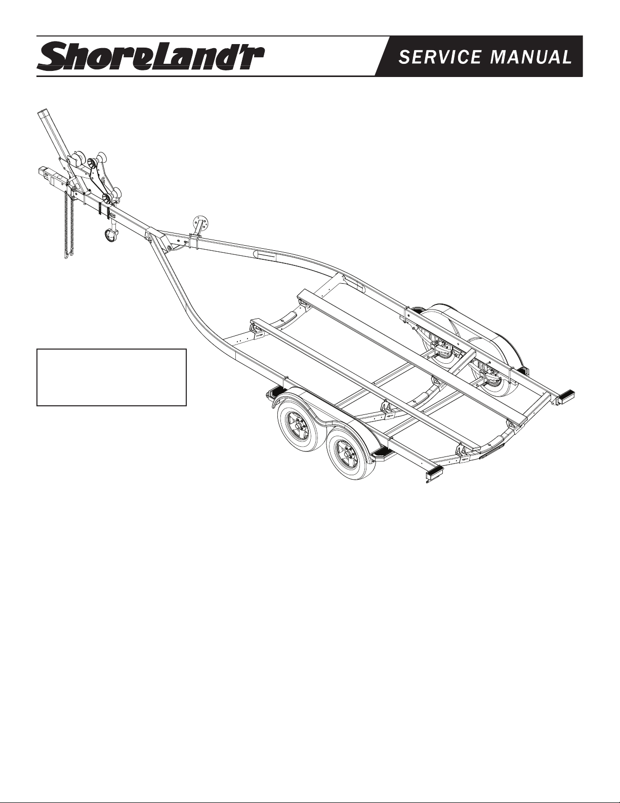
®
SRV59TBBAL-03 & SRV59TBBAL-22
WARNING: The 2” ball used
to tow this trailer must have
a 7500 lb. rating.
SRV59TBBAL-_ _
69082 Literature Bag - Trailers - Brakes
69014-_ _ Frame Bundle
*ST215/75R14C Alum Star Rim
67326 Hdwe Bag - Bulk Parts
6238600 Rocker Bag - Tandem
69352 Brake Kit - Tandem Axle Connection
3310050 Jack 800 lb. Swivel
3310053 Jack Mounting Hardware Bag
4610048 Spring, 5-Leaf
*Check with your dealer/customer service representative for current tire/rim assembly part number.
ShoreLand’r offers its product line in painted nishes. When ordering
parts, it is important that you specify the nish or color you have on
your product. The 5-digit number along with a 2-digit space _ _, note
that the parts can be purchased in various nishes.
03..........Black
22..........Red
Midwest Industries, Inc. Ida Grove, IA 51445 800.859.3028 www.shorelandr.com 0003249
Page 1 Rev G 04/10/2009
SRV59TBBAL Specications
Capacity 5940 lbs.
GVWR: 7480 lbs.
GAWR: 3740 lbs.
Ship Wt: 1280 lbs.
Frm Size: 2X5 (10 Ga.)
Tire Size: ST215X75R14C
Rim Size: 14 X 6 “J”
Brake: Surge Hydraulic (Disc)
Coupler: 2”
Hitch Ball: 7500 lb. rating
Safety Chain: 7100 lbs.
Suspension: 25” Hook
Tongue Size: 3X5X63” Swing Tongue
Table of Contents
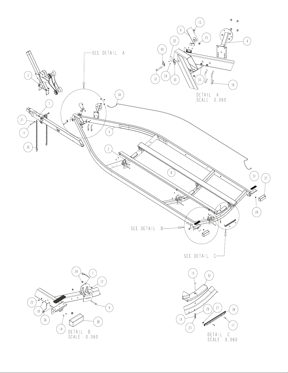
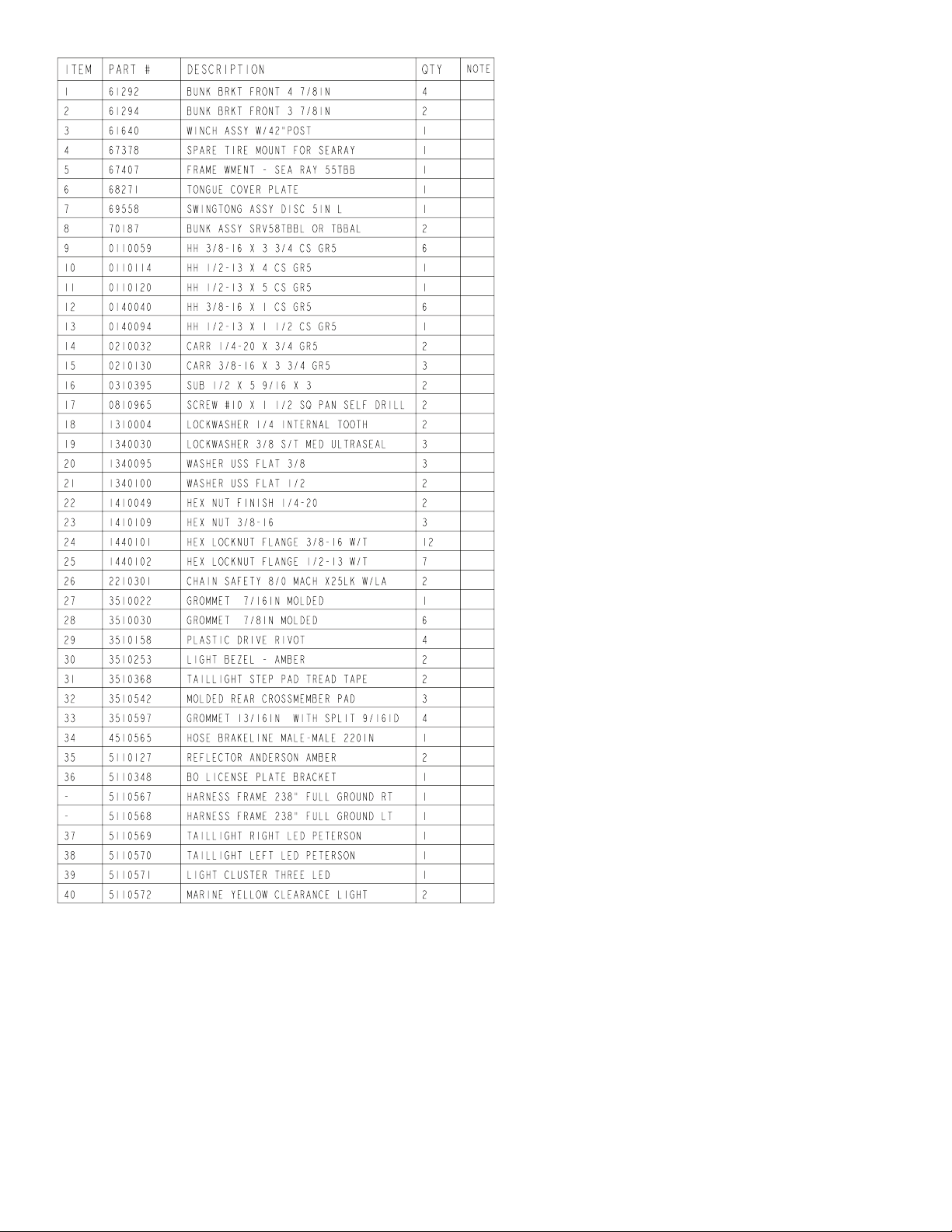
Frame Drawing & Bill of Materials .........................................2-3
Swing Tongue, Actuator, Safety Chain (Disc) ........................2-3
SP Winch / Jack Drawing & BOM .........................................4
Tire Size & Carrying Capapcity Chart ...................................5
Axle Assembly Dwg / BOM (Disc) .........................................5-6
More Information ...................................................................7-8
Page 2
Midwest Industries, Inc. Ida Grove, IA 51445 800.859.3028 www.shorelandr.com 0003249
Page 2 Rev G 04/10/2009
Page 3
Midwest Industries, Inc. Ida Grove, IA 51445 800.859.3028 www.shorelandr.com 0003249
Page 3 Rev G 04/10/2009
Page 4

Midwest Industries, Inc. Ida Grove, IA 51445 800.859.3028 www.shorelandr.com 0003249
Page 4 Rev G 04/10/2009
Page 5

Midwest Industries, Inc. Ida Grove, IA 51445 800.859.3028 www.shorelandr.com 0003249
Page 5 Rev G 04/10/2009
Page 6

Tire Size and Carrying Capacity Chart
Tire Size ............................ST215/75R14-C
GVWR ...............................7040 LB.
Carrying Capacity ..............5940 LB.
Axle....................................Disc Brake
Refer to the tire side wall for correct tire pressure.
Midwest Industries, Inc. Ida Grove, IA 51445 800.859.3028 www.shorelandr.com 0003249
Page 6 Rev G 04/10/2009
Page 7

Dealer / Distributor:
Remove all parts banded or taped to the frame assembly.
Locate the bulk hardware and sort according to size.
Tongue:
Slide tongue into the tongue cap on the front of the
trailer, align holes and insert ½” x 4” hex bolt through
the tongue cap and secure with ½” ange lock nut.
Pull wires from the rear of tongue and feed them thru the tongue
cover, slide the tongue cover over the brake line tube that extends from the rear of tongue. Align the hole in the tongue cover, the tongue, and the frame cap insert a ½” x 1-½” hex bolt and
secure with a ½” at washer and a ½” ange lock nut.
Plug harnesses from the tongue into the matching color harness that extends from each side frame; slide the excess
wire back into the tongue. Very carefully form the brake lines
that extends from the tongue and right side frame until they
are aligned. Remove the plug and cap and screw the two
together. Tighten line securely.
Safety Chains:
Take a ½” x 5” hex bolt slide on a ½” at washer and one
(1) of the safety chains; insert the bolt into the hole on the
actuator housing through tongue and out other side. Place
the second safety chain on the bolt followed with a ½” at
washer and secure with a ½” ange lock nut.
Bunk Assembly:
Place the pre-assembled bunks on the preset bunk brackets
and secure with a 3/8” x 1” hex bolt and secure with a 3/8”
ange lock nut. Repeat at each bunk bracket location.
Rockers:
Remove all parts from bag, insert the bushings into the hole
and slide the rocker into the center bracket on the spring
bracket, making sure that the grease zerk points toward the
ground, insert a ¾” x 4 ½” hex bolt from the outside in. Secure with a ¾” lock nut. Repeat process on other side.
Springs/axles:
Mount springs on axle by aligning the stub bolt on the leaf
springs with the hole in the center of the spring pad on
the axle, place a spring clamp on top of the leaf spring.
Slide two (2) ½” x 2-5/16” x 6-½” square u-bolts over the
springs and spring clamp, slide a spring/axle u-bolt pad
over the threaded ends of the u-bolts and secure with ½”
ange lock nuts. Repeat on other side of axle and on other
axle.
Place axle with the brakes to the rear of the trailer, slide a
spring bushing into the rear loop on the spring bracket and
insert a 9/16” x 3-¼” hex bolt from the outside in and secure
with a 9/16” lock nut. Repeat on other side of trailer. Slide
the hook end of the spring over the bushing and swing the
axle up so the hole in the front of the leaf spring aligns with
the rear hole in the rocker, insert 9/16” x 3-¼” hex bolt and
Midwest Industries, Inc. Ida Grove, IA 51445 800.859.3028 www.shorelandr.com 0003249
Page 7 Rev G 04/10/2009
Page 8
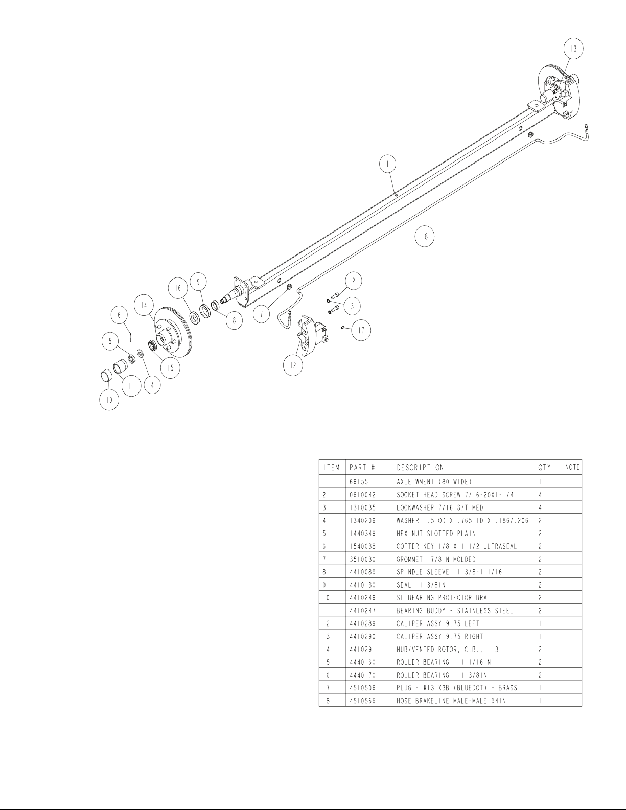
secure with 9/16” lock nut. Repeat on other side. To mount
the front non brake axle, insert a spring bushing into the front
of the rocker and align with the hole, insert a 9/16” x 3-¼”
hex bolt and secure with a 9/16” lock nut. Repeat on the
other side. Swing axle into place so the front of the leaf
spring aligns with the hole in the front loop on the spring
bracket and insert a 9/16” x 3- ¼” hex bolt from the outside in
and secure with a 9/16” lock nut. Repeat on other side.
Remove plug from right side caliper and insert brake hose
assembly securely, place the other end of the hose into the
clip on the spring bracket and secure with the hose clip.
Carefully uncoil the brake line and insert into the hose.
Tire And Wheel Assemblies
Mount the tire and wheel assemblies using the 1/2” ne
threaded tapered lug nuts provided. Tighten to 80-90
ft/lb. of torque using the rotation pattern as shown in the
ShoreLandr’s Owners Manual. Re-torque the lug nuts after
50 miles of driving and then periodically thereafter.
Brakes:
Refer to the Brake Service Manual for service and maintenance.
Midwest Industries, Inc. Ida Grove, IA 51445 800.859.3028 www.shorelandr.com 0003249
Page 8 Rev G 04/10/2009
Page 9

Midwest Industries, Inc. Ida Grove, IA 51445 800.859.3028 www.shorelandr.com 0003249
Page 9 Rev G 04/10/2009
Page 10

3310050 800 lb. Swivel Jack
3310053
Jack Mounting Hardware Bag
Consumer / Owner:
Your SeaRay trailer is designed, assembled and pre-
adjusted to t your boat. If properly maintained it will give
your boat maximum support and many years of care free
service.
Follow these instructions before using your trailer:
Read your ShoreLand’r Owner’s Guide and all safety
decals on the trailer.
Wash and wax your trailer regularly. Always rinse your
trailer after each use, especially when boating in salt or
brackish water.
The law requires that the white ground wire on both the
trailer wire harness and the vehicle harness be properly
grounded.
Re-check all fasteners for tighteness before towing.
Contact your authorized ShoreLand’r dealer if you experience a problem with your trailer. To locate a dealer,
please use www.shorelandr.com - dealer locator feature.
For further information or assistance, contact
ShoreLand’r at 1-800-859-3028 or visit www.shore-
landr.com.
Midwest Industries, Inc. Ida Grove, IA 51445 800.859.3028 www.shorelandr.com 0003249
Page 10 Rev G 04/10/2009
 Loading...