

Page 1
®
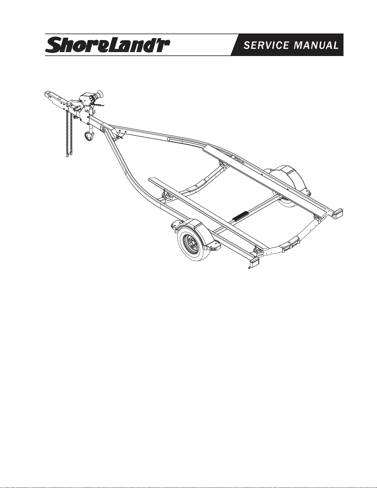
SRV24-08, SRV24B-08, SRV24-18 & SRV24B-18
SeaRay 2X4 Full Bunk Trailers
SRV24-08 Sea Ray 2X4 Full Bunk
62340 Literature Bag - Trailers
6690818 Frame Bundle - SR V24 Galv
66913 Hardware Bag - Bulk Parts
4300237 ST185/80R13C MR Tire/Galv Dir Rim
SRV24B-08 Sea Ray 2X4 Full Bunk - Brake
62340 Literature Bag - Trailers
6728318 Frame Bundle - SR V24B
66296 Hardware Bag - Bulk Parts
4300237 ST185/80R13C MR Tire/Galv Dir Rim
Tire Size and Carrying Capacity Chart
Tire Size ........................... ST185/80R13-C
GVWR .............................. 2960 LB.
Carrying Capacity ............ 2400 LB.
Axle .................................. Brake/ non-brake
Refer to the tire side wall for correct tire pressure.
Midwest Industries, Inc. Ida Grove, IA 51445 800.859.3028 www.shorelandr.com M301236
SRV24-18 Sea Ray 2X4 Full Bunk
62340 Literature Bag - Trailers
6690808 Frame Bundle - SR V24B PW
66913 Hardware Bag - Bulk Parts
4300236 ST185/80R13C MR Tire/MS Dir Rim
SRV24B-18 Sea Ray 2X4 Full Bunk - Brake
62340 Literature Bag - Trailers
6692908 Frame Bundle - SR V24B PW
66296 Hardware Bag - Bulk Parts
4300236 ST185/80R13C MR Tire/MS Dir Rim
Axle Adjustment
This trailer is equipped with a non-adjustable axle. Tongue
weight of this trailer is directly related to the placement of the
gear in the boat.
Best towing is achieved when the tongue weight is 5-7% of
the total gross load of the complete unit.
Page 1 of 12
Page 2
Midwest Industries, Inc. Ida Grove, IA 51445 800.859.3028 www.shorelandr.com M301236
Page 2 of 12
Page 3
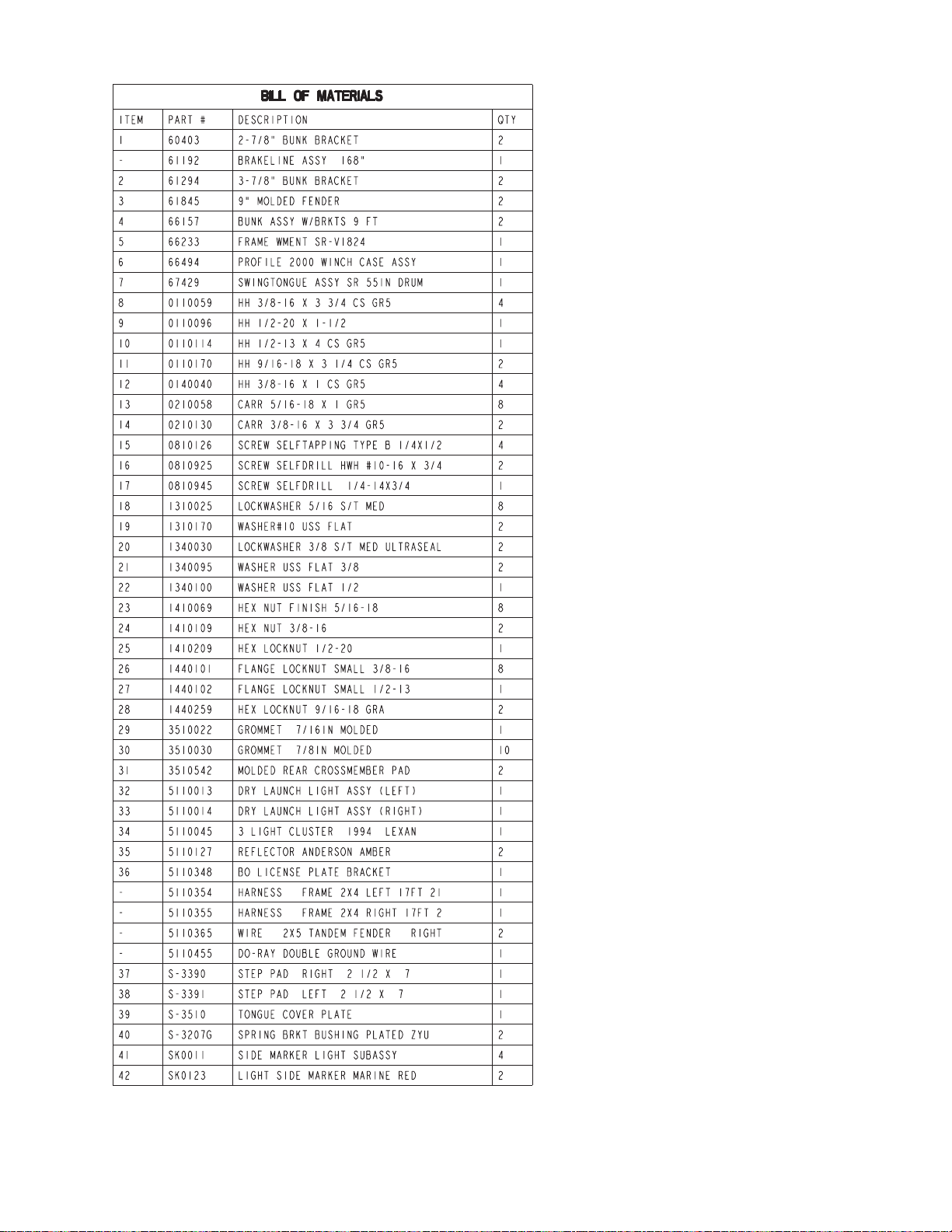
FINAL ASSEMBLY INSTRUCTIONS
Remove the hardware bag from the frame, remove
parts and sort by size.
TONGUE
The tongue comes shipped banded to the bunks.
Cut the banding and position the tongue into the
tongue channel of the frame.
Line the holes in the tongue with the holes in the
tongue channel. Install the 1/2” x 4” hex bolt in the
front cross hole and secure with a 1/2” lock nut.
Remove the wire harness from the rear of the tongue.
Place the wire harness and the brake line (If
equipped with brakes) through the hole provided in
the tongue cover plate. (See Detail A).
Secure the tongue cover plate in position with the
same 1/2” x 1-1/2” hex bolt that secures the back of
the tongue to the tongue channel of the frame.
Secure with a 1/2” lock nut. Tighten both bolts just
installed.
Plug the tongue wire harness ends into the frame
harnesses by matching colors and ends. Push the
extra wire provided either into the rear of the tongue
or else remove the grommets in the side frames and
place the extra wire in the side frame. Replace the
grommets just removed. Attach the ring on the white
ground wire to the main frame with the selftapping screw provided. A hole is provided in the
rear tongue channel support.
(FOR BRAKE INSTALLATION ONLY)
Locate the brass brake line coupling. Remove the
plastic cap and thread the brake line coming out the
rear of the tongue into one end of the coupling. Bend
the line in a smooth gradual radius being careful not
to kink the line. Bend so it can be mated to the brake
line from the side frame. Once aligned thread the
side frame brake line into the other end of the
coupling. Tighten both lines into the coupling.
SAFETY CHAINS
The safety chains are shipped installed.
SPRINGS
The springs are shipped already installed to the axle.
It is ready to install to the frame.
Midwest Industries, Inc. Ida Grove, IA 51445 800.859.3028 www.shorelandr.com M301236
Page 3 of 12
Page 4
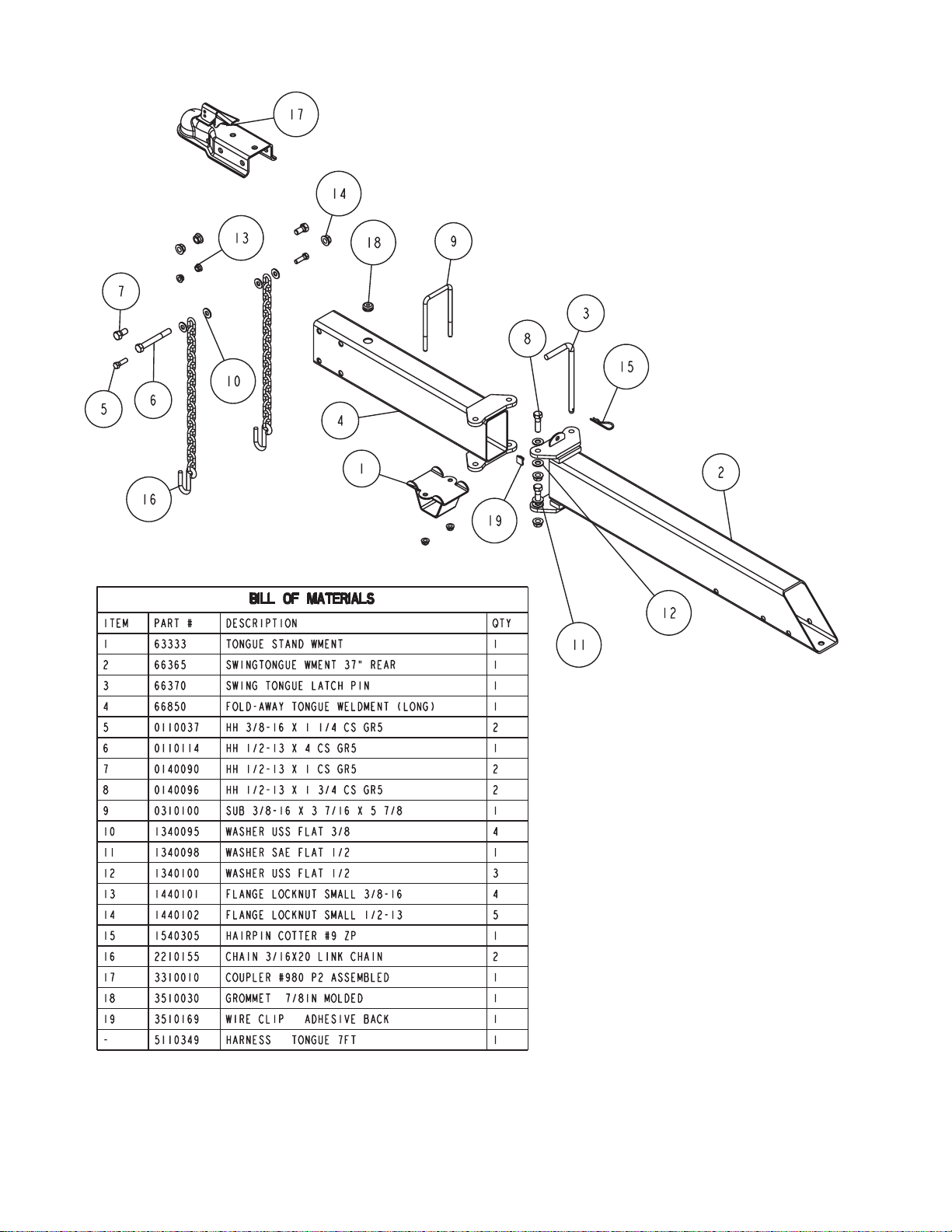
Swing Tongue Assembly
for Non-Brake Axle
Midwest Industries, Inc. Ida Grove, IA 51445 800.859.3028 www.shorelandr.com M301236
Page 4 of 12
Page 5

Swing Tongue Assembly
for Drum Brake Installation
Midwest Industries, Inc. Ida Grove, IA 51445 800.859.3028 www.shorelandr.com M301236
Page 5 of 12
Page 6

Swing Tongue Assembly
for Disc Brake Installation
Midwest Industries, Inc. Ida Grove, IA 51445 800.859.3028 www.shorelandr.com M301236
Page 6 of 12
Page 7

Profile 2000 Winch
with Jack
WINCH POST ASSEMBLY
The winch post assembly is assembled and
pre-adjusted to fit the bow eye of the boat. Attach
the winch post assembly to the tongue using 31/2” x 4 carriage bolts and hex flange lock nuts.
Align the flats on the winch shaft with the flats in
the hole of the winch handle. Slip onto the shaft
and secure with the nut provided. Tighten.
Note: All nuts and bolts must be tightened before
towing.
Midwest Industries, Inc. Ida Grove, IA 51445 800.859.3028 www.shorelandr.com M301236
Page 7 of 12
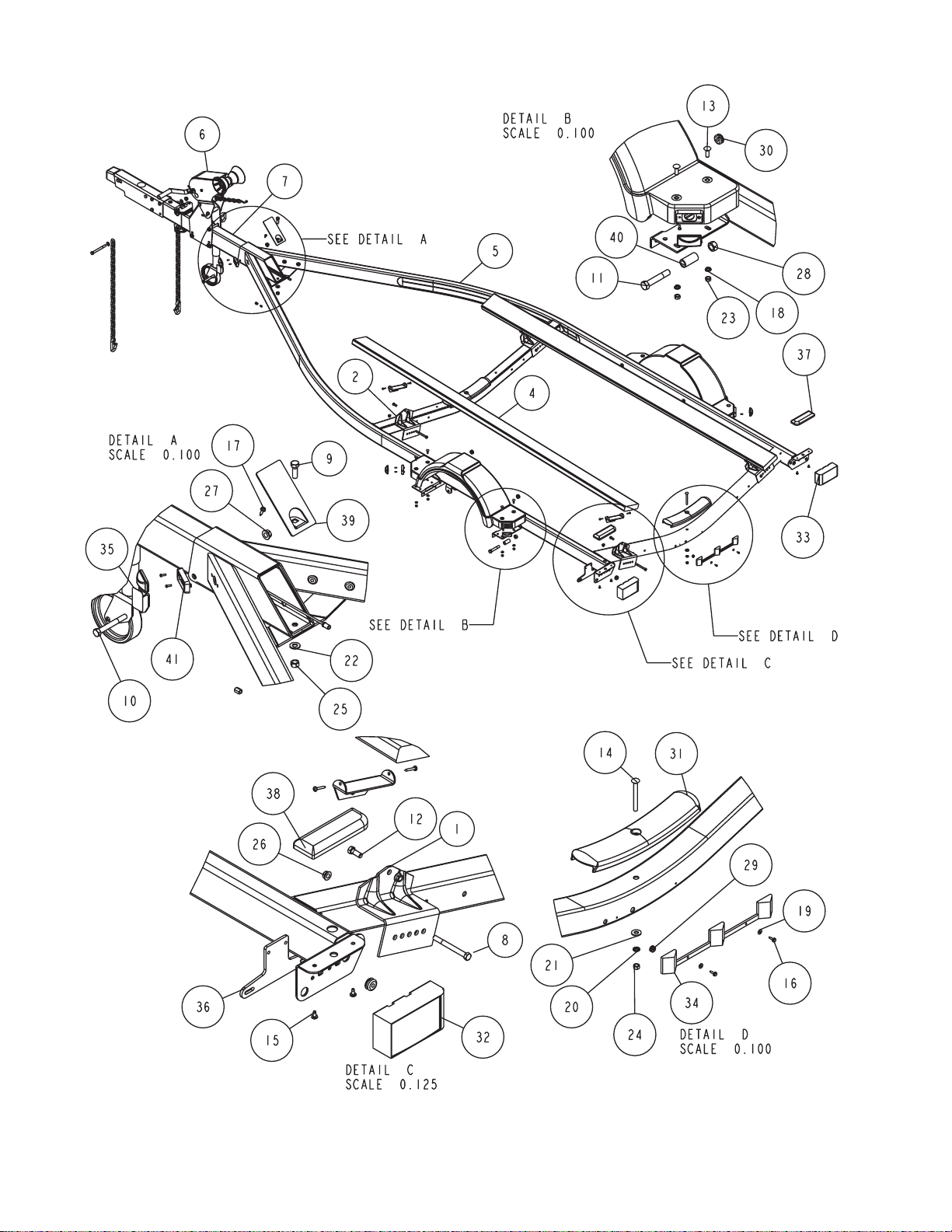
Page 8

AXLE
See Detail B, page 2.
Place one of the spring bracket bushings into
the rear of the spring bracket and secure with
a 9/16” x 3-1/4” hex bolt and hex lock nut.
Repeat in other spring bracket.
Position the axle under the frame, then hook
the hook end of the spring around the
bushings just installed. Note that if the axle is
positioned too low when trying to hook, the
hooks will not hook around the bushings.
Raise the front of the springs up so they align
with the front hole of the spring bracket.
Secure in place with 9/16” x 3-1/4” hex bolts
and lock nuts. Tighten all spring bolts at this
time.
Midwest Industries, Inc. Ida Grove, IA 51445 800.859.3028 www.shorelandr.com
M301236
Page 8 of 12
Page 9

Non-Brake Axle Assembly
Midwest Industries, Inc. Ida Grove, IA 51445 800.859.3028 www.shorelandr.com M301236
Page 9 of 12
Page 10
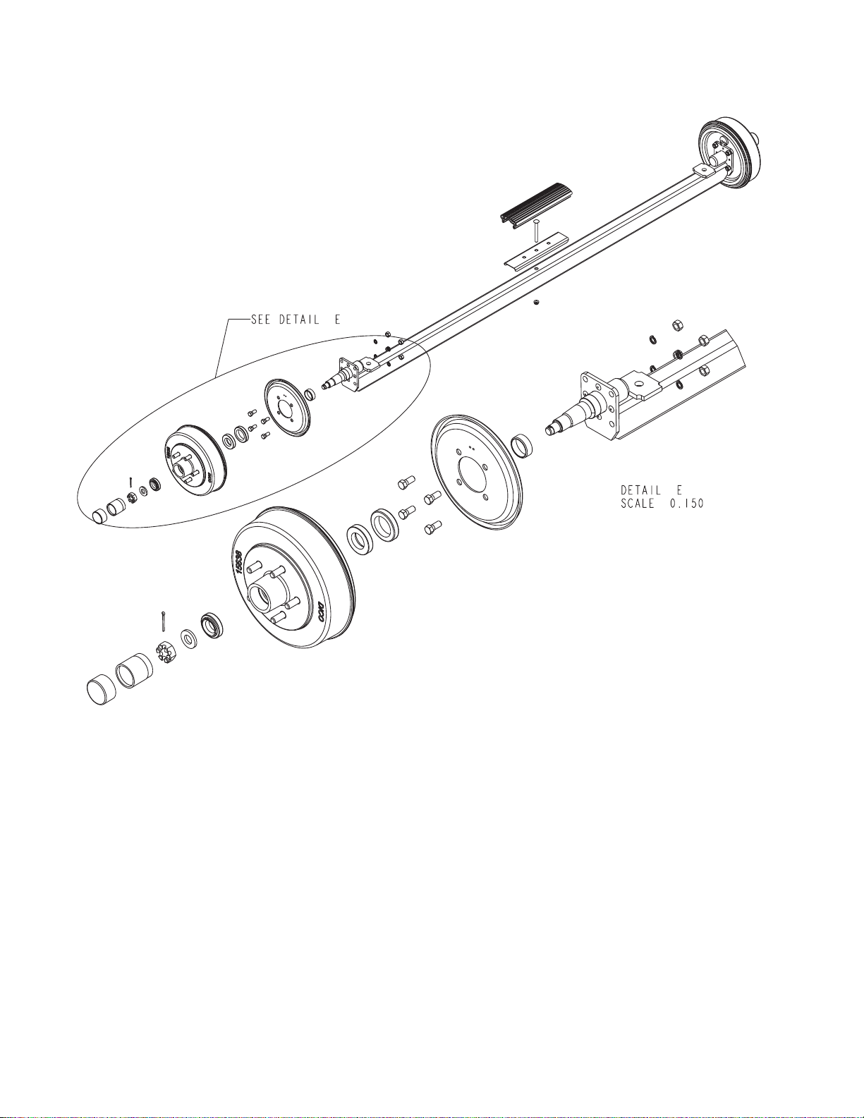
Drum Brake Axle Assembly
ONE AXLE DRUM BRAKE INSTALLATION
Cut the tape securing the brake line hose to the axle. Place
the end of the hose up through the hole provided in the brake
line clip bracket. Secure in place with the hose clip provided.
Remove the plastic cap from the end of the frame brake line
coming out of the side frame by the axle. Carefully uncoil the
brake line so that it will reach the end of the hose just
attached to the brake line clip bracket. Thread the brake line
fitting into the brake line hose. Tighten. The axle assembly
has been pre-bled at the factory during assembly.
Fill the actuator reservoir with brake fluid and bleed the line
per the instructions in the brake manual. All bleeding to the
line can be done through the bleeder on the right wheel
cylinder For bleeding instructions see the ShoreLand’r
Owners Manual.
Midwest Industries, Inc. Ida Grove, IA 51445 800.859.3028 www.shorelandr.com M301236
ONE AXLE DISC BRAKE INSTALLATION
(Galvanized Models Only)
Cut the tape securing the brake line hose to the axle.
Remove the brass plug from the port in the brass block on
the right brake caliper. Thread the brake hose male end into
the port from which the plug was removed and tighten. Place
the other end of the hose up through the hole provided in the
brake line clip bracket. Secure in place with the hose clip
provided.
Remove the plastic cap from the end of the frame brake line
coming out of the side frame by the axle. Carefully uncoil the
brake line so that it will reach the end of the hose just
attached to the brake line clip bracket. Thread the brake line
fitting into the brake line hose. Tighten. The axle assembly
has been pre-bled at the factory during assembly. All
bleeding to the line can be done through the bleeder on the
right caliper. For bleeding instructions see the ShoreLand’r
Disc Brake Manual.
Page 10 of 12
Page 11

Disc Brake Axle Assembly
Midwest Industries, Inc. Ida Grove, IA 51445 800.859.3028 www.shorelandr.com M301236
Page 11 of 12
Page 12

BUNKS
See Detail C on page 2.
Position the bunks onto the brackets already installed to the
cross members. Attach the bunks to the bunk brackets using
3/8” x 1” hex bolts and hex flange lock nuts. The 3/8” bolts
can be tightened but do not over tighten because the bunks
should be allowed to rotate slightly to conform to the boat
bottom once the boat is set on the trailer.
Note: All nuts and bolts must be tightened before towing.
The law requires that the white ground wire on both the tongue
wire harness and vehicle harness be properly grounded to
respective trailer and vehicle frames.
Trailer Adjustments
The adjustment of the trailer to your boat is very important
not only for the trailer, but also the boat. Failure to do so may
lead to potential failure or damage to either the trailer or boat.
Adjust as follows:
Winch Post
Slide the winch post base backward on the tongue until the
bow roller comes in contact with the boat. This bow roller
needs to be positioned directly above the boat bow eye to
prevent your boat from moving forward in the event of a
sudden stop. This adjustment is made at the factory and
should be correct for your boat. However, it can be moved up
or down by removing the rear bolt that mounts the winch head
to the base. When this bolt is removed, the head can be rotated up or down to reach the desired height required to fit
your boat. Once in this position, align the closest pair of holes
in the brackets and reinsert the bolt just removed. Tighten.
Attach the winch strap and crank winch tight. Attach the bow
eye safety chain into the bow eye of the boat as well. This is
just another level of protection to keep your boat and trailer
together as one unit.
Adjustments are now complete.
Re-check all fasteners on the complete trailer to make sure
they are all tight and ready for towing. All fasteners should be
periodically check before towing.
Refer to your ShoreLand’r Owner’s Packet for warranty
information.
Midwest Industries, Inc. Ida Grove, IA 51445 800.859.3028 www.shorelandr.com M301236
Page 12 of 12
 Loading...