

Page 1

®
SMV15
SMV15 SMOKER 1.5X3 TRAILER.
Table of Contents: Page
3310050 Jack 1000 lb Swivel
3310053 Jack Mounting Hardware Bag
67542-- Hardware Bag - Coupler & Chains
80514-- Frame Bundle SMV15
60493-- Tongue - 60”
62340 Literature Bag - Trailers
*5.30 X 12-C Mod Rim Tire Assy.
*Check with your dealer/customer service representative for current tire/rim assembly part number.
ShoreLand’r offers its product line in painted nishes. When ordering parts, it is important that you specify the nish or color you have
on your product. The 5-digit number along with a 2-digit space _ _,
note that the parts can be purchased in various nishes.
00..........Galvanized
03..........Black
Midwest Industries, Inc. Ida Grove, IA 51445 800.859.3028 www.shorelandr.com 0004083
Page 1 Rev A 04/27/2009
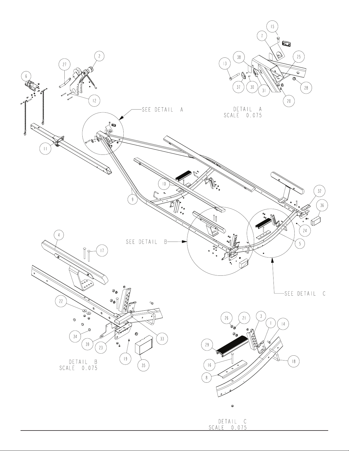
Frame Drawing & Bill of Materials .........................................2-3
Safety Instructions ................................................................. 3
Winch Dwg/BOM. ..................................................................4
Bunk Dwg/BOM ..................................................................... 5
Chassis Dwg/BOM ................................................................6
Axle Dwg/BOM ......................................................................7
Tongue & Coupler Assy’s .......................................................8
Loadguide Assembly .............................................................9
Assembly Instructions............................................................10
Trailer Adjustments ................................................................ 10
Page 2
Midwest Industries, Inc. Ida Grove, IA 51445 800.859.3028 www.shorelandr.com 0004083
Page 2 Rev A 04/27/2009
Page 3

Refer to your ShoreLand’r Owner’s
Guide and other decals on trailer for
additional information.
SAFETY INSTRUCTIONS
4810709
Proper tongue weight must be maintained.
Rev C 8/28/06
Before towing, check the following to ensure
that:
1. All parts, bolts, nuts and wheel lug
nuts are tight.
2. All wheel lug nuts must be tightened
to a minimum torque rating of 85 ft/lb.
3. Lug nuts must be re-torqued after the
first 50 miles, then periodically there
after.
4. Tires are inflated to manufacturer’s
standards. (See tire sidewall)
5. Wheel bearings have adequate
grease.
6. Hitch ball is the proper diameter and
has a rating equal to or greater than
the GVWR of the trailer.
7. Coupler is properly attached and
secured to coupler ball.
8. Trailer safety chains are crossed
under the tongue and attached to
towing vehicle.
9. All lights are operational. Note: It is
recommended that the trailer lights
be disconnected before backing into
the water.
10. Tie downs, winch strap and bow eye safety chain are secure.
11. Trailer tongue jack is in up or travel
position.
Midwest Industries, Inc. Ida Grove, IA 51445 800.859.3028 www.shorelandr.com 0004083
Page 3 Rev A 04/27/2009
Page 4

Midwest Industries, Inc. Ida Grove, IA 51445 800.859.3028 www.shorelandr.com 0004083
Page 4 Rev A 04/27/2009
Page 5

Midwest Industries, Inc. Ida Grove, IA 51445 800.859.3028 www.shorelandr.com 0004083
Page 5 Rev A 04/27/2009
Page 6

Midwest Industries, Inc. Ida Grove, IA 51445 800.859.3028 www.shorelandr.com 0004083
Page 6 Rev A 04/27/2009
Page 7

Midwest Industries, Inc. Ida Grove, IA 51445 800.859.3028 www.shorelandr.com 0004083
Page 7 Rev A 04/27/2009
Page 8

Midwest Industries, Inc. Ida Grove, IA 51445 800.859.3028 www.shorelandr.com 0004083
Page 8 Rev A 04/27/2009
Page 9

Midwest Industries, Inc. Ida Grove, IA 51445 800.859.3028 www.shorelandr.com 0004083
Page 9 Rev A 04/27/2009
Page 10

Final Assembly Instructions
Remove the small parts from the frame by cutting the bands. Remove
the bolt bag and sort all nuts and bolts by size.
Tongue:
Remove the tongue assembly from the frame bundle and install into
the tongue channel and secure with a 1/2” 4” hex bolt in the side of the
tongue and tongue channel. Secure with a 1/2” ange lock nut.
Bunk:
Mount the adjustable bunk brackets with the adjustable bunk clamps to
the crossmembers in a location that would best t your watercraft. Secure with 1/2” X 3-9/16” X 3” square U-bolts and 1/2” ange lock nuts.
Secure the bunk assemblies to the adjustable bunk brackets just in-
stalled using 3/8” X 1” hex bolts and 3/8” ange lock nuts.
Tongue Wires:
Refer to parts drawing on page 2 for placement.
Install the tongue wire harness through the top forward wire hole and
exit the rear of the tongue channel on the frame. Install grommets and
plug the tongue wire into the frame harness by color.
DO NOT OVER TIGHTEN - The bunks must pivot freely to conform
to the boats hull.
Place the tongue cover over the rear of the tongue channel and secure
with a1/2 x 1 1/2” hex bolt and a 1/2” at washer and 1/2” ange lock
nut.
Tire and Wheel Assemblies
Mount the tire and wheel assemblies using the 1/2” ne threaded ta-
pered lug nuts provided. Tighten to 80-90 ft/lb. of torque using the rota-
Safety Chain:
Insert a 3/8” X 1-1/4” hex bolt with a 3/8” at washer and safety chain
through the lower hole on the front of the tongue. Secure with a 3/8” at
tion pattern as shown in the ShoreLandr’s Owners Manual. Re-torque
the lug nuts after 50 miles of driving and then periodically
thereafter.
washer and 3/8” ange lock nut. Repeat the procedure on the opposite
side of the tongue.
Coupler:
Mount the coupler onto the tongue with one (1) 1/2” X 4” hex bolt into
the rear of the coupler and tongue and using two (2) 1/2” X 1” hex bolts
into the two (2) front holes on the coupler and tongue. Secure with 1/2”
Adjustments:
Winch:
Once the boat is positioned on the trailer, adjust the winch post to the
boat, adjust the winch post to the boat. Adjust the bow stop bracket so
that the rubber bow stop is just above the bow eye.
ange lock nuts.
Loadguides
Winch:
Secure the winch post to the tongue with three (3) 3/8” X 4” hex bolts
and 3/8” ange lock nuts. Mount the winch handle to the winch using
the special nut provided. Tighten with winch post in a location that best
ts your water craft.
With the boat loaded and centered on the trailer. Secure the loadguides
using the hardware in bag 60537 which has been banded to the frame
bundle. Open bag sort parts, place loadguide on frame over the holes
provided in the rear section of the frame and insert 3/8 x 4” carriage
bolts into the square hole in the bracket and thru the frame. Secure with
a washer and 3/8” ange locknut. Repeat this process until all four bolts
Axle and Wheel Assembly
are in place and then tighten these bolts and nuts securely.
Locate the axle for the trailer. Note that there is not a right or left to the
axle assembly. Place one of the springs on top of the spring pad welded
to the axle. Drop two (2) 3/8” x 2-3/16” x 2” U-bolts over the springs and
down through the holes in the spring pad. Secure with 3/8” ange lock
nuts. Repeat this process on the other spring mounting it so that it is
oriented on the axle the same as the rst spring.
Slip a spring bushing spacer into the rear of the spring bracket, align
the bushing with the hole in the bracket and secure in position using a
1/2” x 3” hex bolt and 1/2” ange lock nut. Tighten. Repeat on the other
spring bracket.
Slide the axle assembly under the trailer frame, raise up and slide the
rear of the springs above the bushings just installed. Rotate the assembly up until the front spring eyes align with the front holes in the
spring bracket. Insert a 9/16” x 3-1/4” hex bolt and secure with a 9/16”
lock nut. Tighten. Tighten the U-bolt attaching the springs to the axles
at this time and any other bolts that may have been left loose for ease
of assembly.
Place the tire and wheel assemblies on the hubs and secure with the
1/2” tapered lock nuts.
Midwest Industries, Inc. Ida Grove, IA 51445 800.859.3028 www.shorelandr.com 0004083
Page 10 Rev A 04/27/2009
 Loading...