

Page 1
®
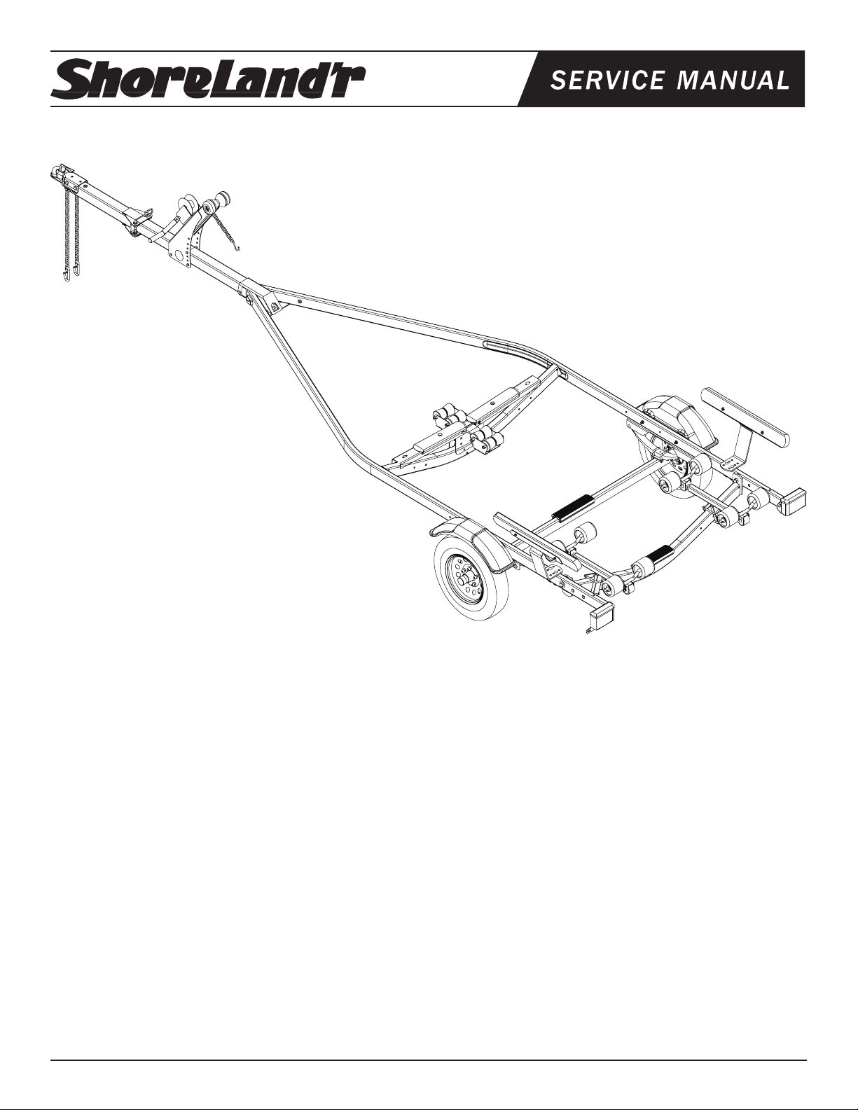
SMR15
SMR15 SMOKER 1.5X3 TRAILER
Table of Contents: Page
3310050 Jack 1000 LB. Swivel
3310053 Jack Mounting Hardware Bag
69435-- Hardware Box Roller R15
69175-- Keel Cradle Bundle 1x3/2x3 Roller
80550-- Frame Bundle SMR15
62340 Literature Bag - Trailers
*5.30 X 12-C Mod Rim Tire Assy.
*Check with your dealer/customer service representative for current tire/rim assembly part number.
ShoreLand’r offers their product line in either galvanized or painted
nish. When ordering parts it is important that you specify the nish
or color you have on your product. The ve (5) digit number along
with a two (2) digit space _ _, note the parts which can be purchased
with various nishes. When ordering these items use the ve (5) digit
number along with a two (2) digit sufx for the proper nish.
00..........Galvanized
03..........Black
Midwest Industries, Inc. Ida Grove, IA 51445 800.859.3028 www.shorelandr.com 0004082
Page 1 Rev A 04/27/2009
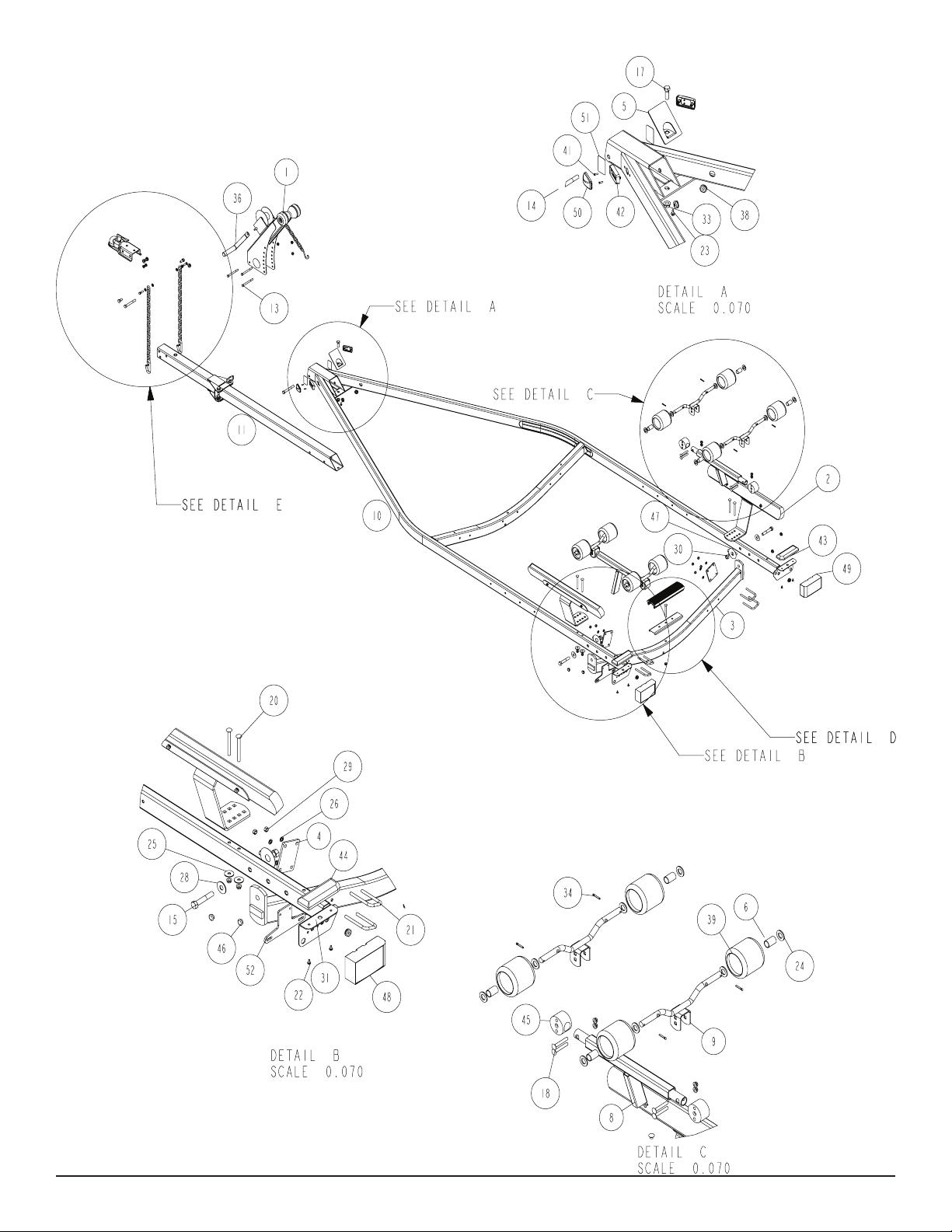
Exploded Frame Drawing ..................................................... 2
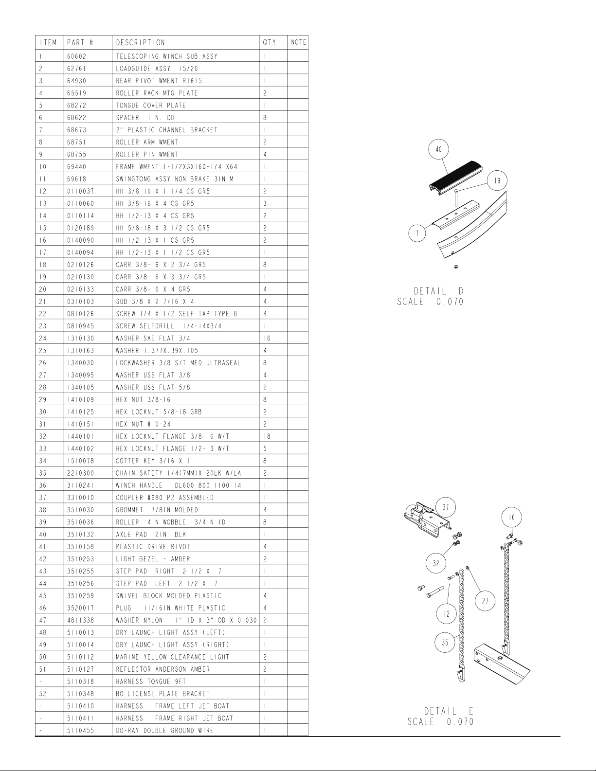
Frame BOM/Crossmember Pad/Coupler & Chains. ..............3
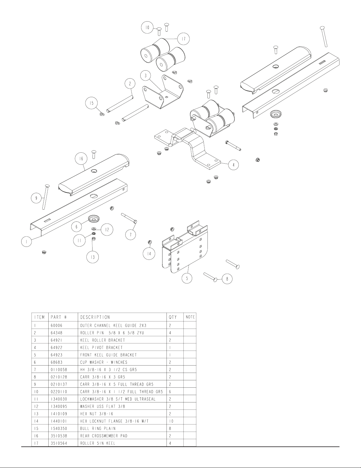
Keel Guide Dwg/BOM ...........................................................4
Winch Dwg/BOM ...................................................................5
Chassis Dwg/BOM & Axle Dwg/BOM ....................................6-7
Swingtongue Dwg/BOM ........................................................8
Loadguide Dwg/BOM ............................................................9
Assembly Instructions............................................................10
Trailer Adjustments ................................................................10-11
Page 2
Midwest Industries, Inc. Ida Grove, IA 51445 800.859.3028 www.shorelandr.com 0004082
Page 2 Rev A 04/27/2009
Page 3
Midwest Industries, Inc. Ida Grove, IA 51445 800.859.3028 www.shorelandr.com 0004082
Page 3 Rev A 04/27/2009
Page 4
Midwest Industries, Inc. Ida Grove, IA 51445 800.859.3028 www.shorelandr.com 0004082
Page 4 Rev A 04/27/2009
Page 5

Midwest Industries, Inc. Ida Grove, IA 51445 800.859.3028 www.shorelandr.com 0004082
Page 5 Rev A 04/27/2009
Page 6

Midwest Industries, Inc. Ida Grove, IA 51445 800.859.3028 www.shorelandr.com 0004082
Page 6 Rev A 04/27/2009
Page 7

Midwest Industries, Inc. Ida Grove, IA 51445 800.859.3028 www.shorelandr.com 0004082
Page 7 Rev A 04/27/2009
Page 8

Midwest Industries, Inc. Ida Grove, IA 51445 800.859.3028 www.shorelandr.com 0004082
Page 8 Rev A 04/27/2009
Page 9

Midwest Industries, Inc. Ida Grove, IA 51445 800.859.3028 www.shorelandr.com 0004082
Page 9 Rev A 04/27/2009
Page 10

Final Assembly Instructions
Remove the small parts from the frame by cutting the bands. Remove
the bolt bag and sort all nuts and bolts by size.
made by removing the cotter key, at washer, spacer, and roller from
the roller pin and placing the spacer next to the inside washer, then the
roller, the washer, and re-inserting the cotter key.
Tongue:
Remove the tongue assembly from the frame bundle and install into
the tongue channel and secure with a 1/2” 4” hex bolt in the side of the
tongue and tongue channel. Secure with a 1/2” ange lock nut.
Tongue Wires:
Install the tongue wire harness through the top forward wire hole and
exit the rear of the tongue channel on the frame. Install grommets and
plug the tongue wire into the frame harness by color.
Roller Assembly:
Mount the roller assemblies to the rear pivot in a location that best ts
your watercraft. Secure with 3/8” X 2-7/16” X 4” square u-bolts and 3/8”
X 2-7/16” X 4” square u-bolts and 3/8” ange lock nuts.
Axle and Wheel Assembly
Locate the axle for the trailer. Note that there is not a right or left to
the axle assembly. Place one of the springs on top of the spring pad
welded to the axle as shown in Diagram D. Drop two (2) 3/8” x 2-3/16”
x 2” U-bolts over the springs and down through the holes in the spring
Place the tongue cover over the rear of the tongue channel and secure
with a 1 x 1 1/2” hex bolt a 1/2” at washer and 1/2” ange lock nut.
pad. Secure with 3/8” ange lock nuts. Repeat this process on the other
spring mounting it so that it is oriented on the axle the same as the rst
spring.
Safety Chain:
Insert a 3/8” X 1-1/4” hex bolt with a 3/8” at washer and safety chain
through the lower hole on the front of the tongue. Secure with a 3/8” at
washer and 3/8” ange lock nut. Repeat the procedure on the opposite
side of the tongue.
Coupler:
Mount the coupler onto the tongue with one (1) 1/2” X 4” hex bolt into
the rear of the coupler and tongue and using two (2) 1/2” X 1” hex bolts
into the two (2) front holes on the coupler and tongue. Secure with 1/2”
ange lock nuts.
Slip a spring bushing spacer into the rear of the spring bracket, align
the bushing with the hole in the bracket and secure in position using a
1/2” x 3” hex bolt and 1/2” ange lock nut. Tighten. Repeat on the other
spring bracket.
Slide the axle assembly under the trailer frame, raise up and slide the
rear of the springs above the bushings just installed. Rotate the assembly up until the front spring eyes align with the front holes in the
spring bracket. Insert a 9/16” x 3-1/4” hex bolt and secure with a 9/16”
lock nut. Tighten. Tighten the U-bolt attaching the springs to the axles
at this time and any other bolts that may have been left loose for ease
Winch:
of assembly.
Secure the winch post to the tongue with three (3) 3/8” X 4” hex bolts
and 3/8” ange lock nuts. Mount the winch handle to the winch using
the special nut provided. Tighten with winch post in a location that best
Place the tire and wheel assemblies on the hubs and secure with the
1/2” tapered lock nuts.
ts your water craft.
Tire And Wheel Assemblies
Keel Roller Assembly:
Open box and remove all parts and hardware bag. Open hardware bag
and sort parts.
Mount the tire and wheel assemblies using the 1/2” ne threaded tapered lug nuts provided. Tighten to 80-90 ft/lb. of torque using the rotation pattern as shown in the ShoreLandr’s Owners Manual. Re-torque
the lug nuts after 50 miles of driving and then periodically
Place 64923_ _ front keel guide bracket over front cross member and
thereafter.
align holes in bracket with those in the front cross and insert 3/8” X
3” carriage bolts from rear to front and secure 3/8” ange lock nuts.
Adjustments:
Place cradle assembly with pin in center in the rear slot on top of the
previously attached bracket with bent ends facing forward. Take outer
channel assemblies and place on top of bracket aligning holes and
insert 3/8” X 3” hex bolts, secure with 3/8” ange lock nuts. In the slots
Keel Roller:
Load boat - Make necessary adjustments to center bracket and tighten
nuts, tighten other nuts only enough to allow assembly to pivot freely.
in the ends of the channel, insert 3/8” X 5” carriage bolts through cross
member and secure 3/8” ange lock nuts.
Winch:
Once the boat is positioned on the trailer, adjust the winch post to the
Roller Arm Assembly:
Remove parts from hardware box and sort parts.
boat, adjust the winch post to the boat. Adjust the bow stop bracket so
that the rubber bow stop is just above the bow eye.
Slide a swivel block onto each end of the roller arm weldments aligning the center hole with the large hole in the round tube. Place a roller
pin weldments over the swivel block align the holes and insert 3/8 x 2
¾” carriage bolts. NOTE: make sure all bolts go in the same direction.
Secure with 3/8 ange lock nuts and tighten only tight enough to secure
Roller Assembly:
Place your boat on the trailer. Determine the spacing on the roller rack.
It may be necessary to adjust your roller rack either further in or out
from the position you have it assemblies. The boat must be adjusted to
miss any keel or strake which might be on your particular boat.
the roller pin snugly to the swivel block. This will allow the pin to swivel
so it will conform to the bottom of the boat. Place a ¾” at washer over
the pin then a roller the spacer and another at washer and then insert
a cotter key through the hole. Bend both sides of the cotter key out to
IMPORTANT: The roller racks should be spaced as far apart as pos-
sible for stability. This in most cases will allow your boat to be as low as
possible on the trailer for better trailering, loading and unloading.
hold the roller in place. Repeat for the other rollers.
Once the roller racks have been spaced properly for your boat, position
Mount the roller arm assemblies just created to the rear pivot with the
bolts that go through the roller pins to the center of the trailer. Slide ubolts around the rear pivot ant through the holes of the mounting plate
and secure with 3/8 ange lock nuts. Adjustment may be made by sliding the roller arms in or out on the rear pivot. Adjustment can also be
the boat on the trailer with the transom ush with the rear roller rack.
Loadguides
With the boat loaded and centered on the trailer. Secure the loadguides
using the hardware in bag 60537 which has been banded to the frame
Midwest Industries, Inc. Ida Grove, IA 51445 800.859.3028 www.shorelandr.com 0004082
Page 10 Rev A 04/27/2009
Page 11

bundle. Open bag sort parts, place loadguide on frame over the holes
provided in the rear section of the frame and insert 3/8 x 4” carriage
bolts into the square hole in the bracket and thru the frame. Secure with
a washer and 3/8” ange locknut. Repeat this process until all four bolts
are in place and then tighten these bolts and nuts securely.
Midwest Industries, Inc. Ida Grove, IA 51445 800.859.3028 www.shorelandr.com 0004082
Page 11 Rev A 04/27/2009
 Loading...