

Page 1
SMB10TM-03
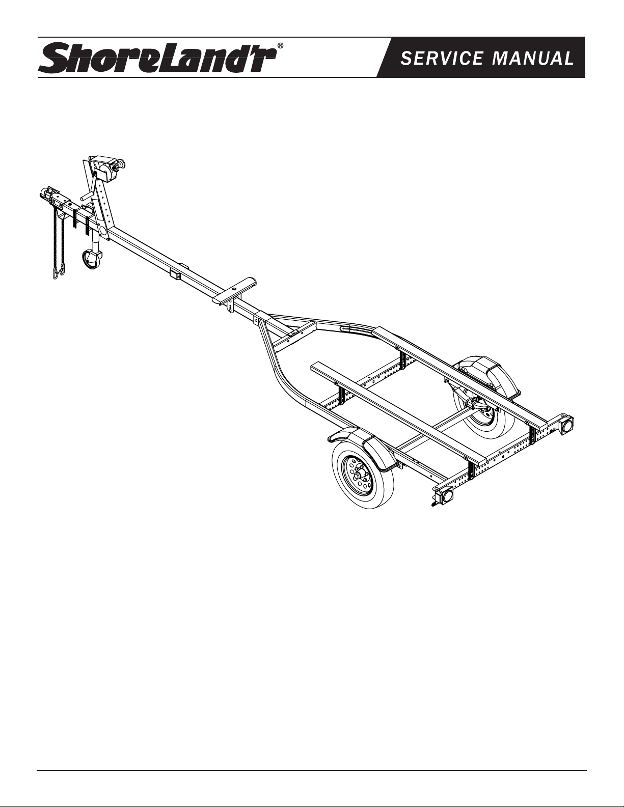
Smoker Fishing 44” Bunk Trailer
SMB10TM-03 Bundles Required:
*5.30 X 12-C Tire/TS Mod Rim ...................2
62340 Literature Bag - Trailers ..............................1
6839803 Frame Bundle - 44” Bunk Bundle ...............1
6553703 Tongue 3X3X14 GA X 8’ 6” .........................1
TA0010 Bow Pad Support - Fishing .........................1
3310050 Jack - 800 lb. Swivel ...................................1
3310053 Jack Mounting Hardware Bag ....................1
*Check with your dealer/customer service representative for current tire/rim assembly part number.
Midwest Industries, Inc. Ida Grove, IA 51445 800.859.3028 www.shorelandr.com 0003920
Page 1 01/25/2008
ShoreLand’r offers its product line in painted nishes. When order-
ing parts, it is important that you specify the nish or color you have
on your product. The 5-digit number along with a 2-digit space _ _,
note that the parts can be purchased in various nishes.
03..........Black
Page 2
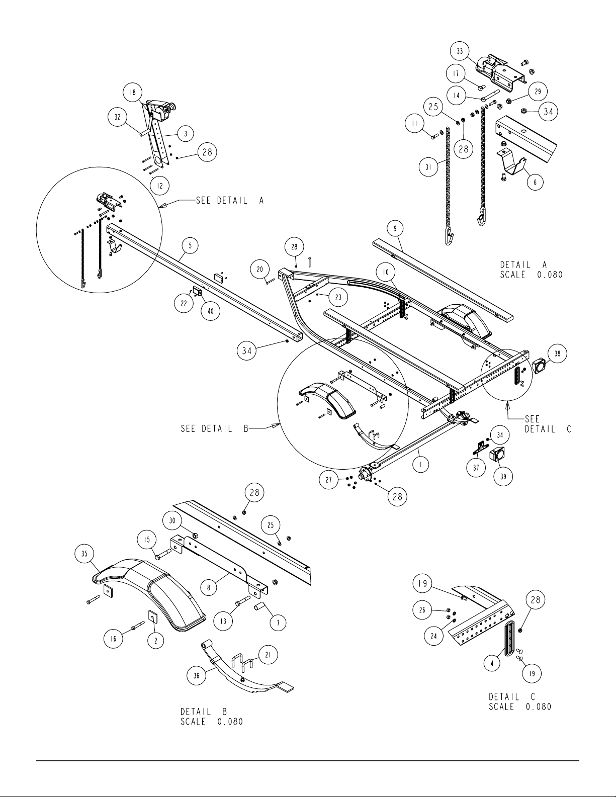
Diagram A
Midwest Industries, Inc. Ida Grove, IA 51445 800.859.3028 www.shorelandr.com 0003920
Page 2 01/25/2008
Page 3
Refer to your ShoreLand’r Owner’s
Guide and other decals on trailer for
additional information.
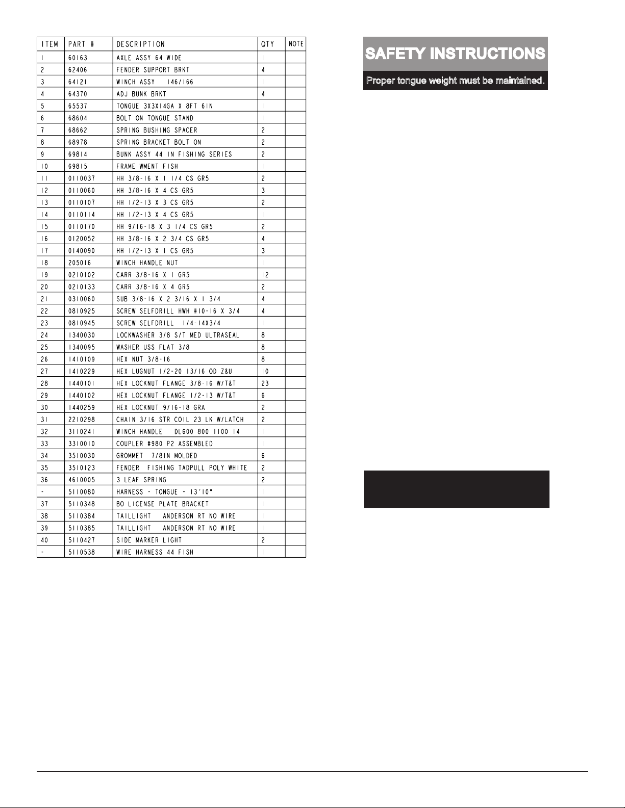
SAFETY INSTRUCTIONS
4810709
Proper tongue weight must be maintained.
Rev C 8/28/06
Before towing, check the following to ensure
that:
1. All parts, bolts, nuts and wheel lug
nuts are tight.
2. All wheel lug nuts must be tightened
to a minimum torque rating of 85 ft/lb.
3. Lug nuts must be re-torqued after the
first 50 miles, then periodically there
after.
4. Tires are inflated to manufacturer’s
standards. (See tire sidewall)
5. Wheel bearings have adequate
grease.
6. Hitch ball is the proper diameter and
has a rating equal to or greater than
the GVWR of the trailer.
7. Coupler is properly attached and
secured to coupler ball.
8. Trailer safety chains are crossed
under the tongue and attached to
towing vehicle.
9. All lights are operational. Note: It is
recommended that the trailer lights
be disconnected before backing into
the water.
10. Tie downs, winch strap and bow eye safety chain are secure.
11. Trailer tongue jack is in up or travel
position.
Recommended carrying capacity is based on shipping weight
of the trailer with standard equipment. Adding optional equipment may decrease the trailer’s carrying capacity.
Tire Size and Carrying Capacity Chart
Tire Size 5.30 X 12-C
GVWR 1495 lb.
Carrying Capacity 1000 lb.
Axle Standard (Non-Brake)
Refer to the tire side wall for correct tire pressure.
Midwest Industries, Inc. Ida Grove, IA 51445 800.859.3028 www.shorelandr.com 0003920
Page 3 01/25/2008
Page 4

TONGUE ASSEMBLY
Place the frame to be assembled on saw horses or stands to assist
in the assembly. Remove all items that are banded to the frame.
Sort the items in the hardware box by item and the hardware by
size.
Locate the tongue for the trailer. Note that there are three different
lengths of tongues designed to t this particular frame. The length
of tongue will determine the length of boat that can be placed on
the trailer when assembled. The 7 foot tongue will accommodate
boats up to 12 feet in length, the 8’-6” tongue will t boats 12-14
feet in length and the 10 foot tongue is used for boats 14-16 feet
long.
Once the proper tongue is identied place it on the stands so it can
be prepared for installation into the frame. Locate the two amber
side marker lights shipped in the hardware box. Uncoil the wire and
insert the plug end into the larger, center hole that is drilled in the
side of the tongue. As the wire is inserted into the hole direct the
wire so that it will go to the forward end of the tongue. Pull the wire
out the front of the tongue. It will be connected to the tongue harness at a later time. Attach the light to the tongue using two (2) No.
10 x 3/4” self-tapping screws provided. Repeat this process on the
other light on the other side of the tongue.
Locate the tongue wire harness. Insert the end of the harness with
the small plug into the hole located in the top of the tongue. Pull
the wire backward through the tongue until the end comes out the
rear of the tongue. As the wire harness is inserted note that there
are two single bullet wires towards the front plug of the tongue wire
harness. Pull these wires forward as the wire harness is inserted
into the tongue. Plug the single wires from the side marker lights
installed earlier into the two single bullets of the tongue harness.
Push the additional back into the front of the tongue to keep it from
damage during use. Place a rubber grommet around the wire harness and in the hole in the top of the tongue to protect the wires
from damage during use.
Route the harness plug at the rear of the tongue through the hole
provided in the side of the tongue. Pull both the plug and the white
ground wire out the hole. They will be attached later once the
tongue is installed in the frame.
this process on the other side of the tongue. Once the bolts are
installed, tighten all nuts left loose at this time.
Insert the tongue assembly through the front channel of the frame
far enough so the rear of the tongue is inserted into the front cross
member. Align the cross hole in the front channel and the tongue
and insert a 3/8” x 4” hex bolt. Secure with a 3/8” ange lock nut.
Place a second 3/8” x 4” hex bolt down through the hole in the rear
of the tongue and the front cross member. Place on a 3/8” ange
lock nut. Tighten.
Connect the tongue wire harness into the side frame harness of
the trailer by matching plugs. Attach the white ground wire of the
tongue harness to the frame using a No. 10 x 3/4” self-tapping
screw provided so that a good ground connection is made between
the frame of the trailer and the tow vehicle. Push all extra wires
used to make the connection back into the tongue. Place a second
rubber grommet into the hole where the wires exit the tongue to
protect them from damage during normal use.
JACK ASSEMBLY
It is recommended that the jack be mounted on the right side of the
tongue. This will place it on the opposite side of the winch handle
to eliminate the possibility of the two interfering when being operated.
Remove the hardware bag from the jack and sort all items by size.
Note that the jack mounting plate has only one pair of holes on one
side of the plate while the other side has holes punched to accommodate either 3”, 4”, or 5” tongue.
Place a 3/8” x 4” hex bolt into the single hole of the mounting plate
so the head of the bolt is on the jack side of the plate.
Once inserted, place one of the mounting channels onto the bolt so
the legs of the mounting channel are pointing away from the jack.
Place on a 3/8” at washer and hex nut. Thread on only far enough
to secure in place.
Repeat the above process on the other single hole of the mounting plate.
Locate the bolt on tongue stand. Look at the bottom side of the
tongue and locate the slotted key slot hole in the tongue. Note that
one end of the tongue stand has a dart or arrow shaped end. With
the tongue stand positioned 90 degrees to the center line of the
tongue, insert the dart or arrow end of the tongue stand into the key
slotted hole. Once it is inserted, turn the tongue stand 90 degrees
so that it now is in line with the center line of the tongue. Attach the
front end of the tongue stand to the tongue using a 1/2” x 1” hex bolt
and ange lock nut. Tighten.
Locate the safety chains. Place a 3/8” at washer on a 3/8” x 1” hex
bolt. Insert the bolt through the last link in the safety chain and then
into the lower hole provided in the front of the tongue. Secure with
Place the jack on the tongue so that the two bolts just installed
are on the top side of the tongue with the jack on the right side
of the tongue and the mounting channels on the other side of the
tongue.
Visually check which of the bottom three holes in the plate will align
just under the bottom side of the tongue. Insert the remaining two
3/8” x 4” hex bolts into these holes and then through the mating
holes in the mounting channel. Secure with 3/8” at washers and
hex nuts.
Rotate the jack into the up position. Slide the jack forward or backward on the tongue to make sure it will not hit the frame of the trailer
when in the up position.
a 3/8” ange lock nut. Tighten. Repeat on the other chain.
Tighten all of the mounting bolts to secure the jack assembly to the
Place the coupler on the top of the tongue. Align the holes in the
tongue.
coupler with the holes in the tongue. Place a 1/2” x 4” hex bolt
through the back holes of the coupler and the tongue. Secure with
Always rotate the jack in the up position before towing the trailer.
a 1/2” ange lock nut but do not tighten at this point.
Place a 1/2” x 1” hex bolt through the front hole on one side of the
coupler and the tongue so that the head of the bolt is to the outside.
Place a 1/2” ange lock nut on the bolt inside the tongue. Repeat
Midwest Industries, Inc. Ida Grove, IA 51445 800.859.3028 www.shorelandr.com 0003920
Page 4 01/25/2008
Page 5

Diagram B
can be shifted to the center line of the keel rollers for proper sup-
port. At that time the bow support pad acts as an additional support
for the keel of the boat similar to a keel roller.
Locate the rear cross member pad (Item #10). Place it on the top
of the formed pad support channel. Drop the pad into the support
channel so that the center plastic ring of the pad ts in the hole of
the channel. Place the assembly onto the support mounting bracket
as shown. Attach the pieces together with a 3/8” X 1-1/2” carriage
bolt down from the top. Secure to the support mounting bracket by
rst installing Item No. 3, cup washer and then a at washer. Place
on a 3/8” lock washer and hex nut. Tighten.
The assembly is attached to the tongue with two 3/8” X 4” carriage
bolts, one on each the top and bottom side of the tongue. They are
secured in place with 3/8” ange lock nuts provided.
Note that the assembly is adjustable both up and down as well as
being able to be slid forward and backward on the tongue. Adjust
to its proper position. Secure in place by tightening the bolts just
installed. Assembly is complete.
WINCH POST ASSEMBLY
The winch post assembly is pre-assembled and is shipped banded
to the frame. See Diagram B. Place the winch post on the tongue in
the approximate location. Attach to the tongue using three (3) 3/8”
x 4” hex bolts and 3/8” ange lock nuts. It can be left loose until the
boat is placed on the trailer for nal adjustment.
Place the winch handle on the drive shaft of the winch by mating
the at sides of the drive shaft with the punched hole in the winch
handle. Secure the handle to the drive shaft with the 1/2” lock nut
provided. Tighten.
BOW SUPPORT PAD ASSEMBLY
The TA0010 Bow Support Pad is used to add additional support to
the keel of your boat in the area over the tongue. It is adjustable
forward and backward as well as up and down. It can be raised to
the proper height to support your boat.
It also serves as a broader area for your boat to rest on, especially
a at bottom boat when it is being loaded. Once loaded the boat
Midwest Industries, Inc. Ida Grove, IA 51445 800.859.3028 www.shorelandr.com 0003920
Page 5 01/25/2008
Page 6

AXLE & WHEEL ASSEMBLY
Locate the axle for the trailer. Note that there isn’t a right or left to
the axle assembly. Place one of the springs on top of the spring
pad welded to the axle. Drop two (2) 3/8” x 2 3/16” x 2” U-bolts over
the springs and down through the holes in the spring pad. Secure
with 3/8” ange lock nuts. Repeat this process on the other spring
assembly up until the front spring eyes align with the front holes in
the spring bracket. Insert a 9/16” x 3-1/4” hex bolt and secure with
a 9/16” lock nut. Tighten. Tighten the U-bolt attaching the springs
to the axles at this time and any other bolts that may have been left
loose for ease of assembly.
mounting it so that it is oriented on the axle the same as the rst
spring.
Place the tire and wheel assemblies on the hubs and secure with
the 1/2” tapered lock nuts.
Slip a spring bushing spacer into the rear of the spring bracket,
align the bushing with the hole in the bracket and secure in position
using a 1/2” x 3” hex bolt and 1/2” ange lock nut. Tighten. Repeat
on the other spring bracket.
TIRE & WHEEL ASSEMBLIES
Mount the tire and wheel assemblies using the 1/2” ne threaded
tapered lug nuts provided. Tighten to 80-90 ft/lb. of torque using the
rotation pattern as shown in the ShoreLandr’s Owners Manual.
Slide the axle assembly under the trailer frame, raise up and slide
the rear of the springs above the bushings just installed. Rotate the
Midwest Industries, Inc. Ida Grove, IA 51445 800.859.3028 www.shorelandr.com 0003920
Page 6 01/25/2008
Re-torque the lug nuts after 50 miles of driving and then periodi-
cally thereafter.
Page 7

BUNK BRACKETS & BUNKS
Locate the bunk brackets. See Diagram A. Note that the front bunk
brackets are located on the front of the crossmember while the rear
bunk brackets are located on the rear of the cross member. Choose
a pair of holes for the bunk location. Attach the bunk brackets to the
cross members using 3/8” x 1” carriage bolts, lock washers and hex
nuts. Hand tighten only because they will have to be adjusted when
the boat is placed on the trailer.
Position the bunks so that they are above the bunk brackets just
installed. Note that the mounting brackets attached to the bunks
are not centered on the bunks but are off center 4 inches. They
can be installed either direction. Positioning them so the extra bunk
is to the rear will allow you to put a longer boat on the trailer. This
adjustment may also be critical when trying to establish the correct
tongue weight.
Attach the bunks to the brackets using 3/8” x 1” carriage bolts and
ange lock nuts. Tighten but do not over tighten, the bunks must be
allowed to pivot so they will conform to the boat when it is placed
on the trailer.
Midwest Industries, Inc. Ida Grove, IA 51445 800.859.3028 www.shorelandr.com 0003920
Page 7 01/25/2008
Page 8

TRAILER ADJUSTMENTS
Place the boat on the trailer so that the transom of the boat is positioned at the rear of the bunks.
Check the boat for clearance with the frame and tongue. Enough
clearance is required between the two so that the boat does not
contact the frame during loading and unloading.
ADJUST AS FOLLOWS:
Pull the boat on the trailer. As you pull the boat on the trailer check
to make sure the bunks are high enough and close enough to keep
the keel of the boat from hitting the cross members as it is loaded
and unloaded. However, it is very important that they are spaced as
far apart as possible because the farther they are spaced apart, the
more stable your boat will be on the trailer when towing. Allow the
boat to rest on the front support pad on the tongue and the bunks.
BUNK ADJUSTMENT
Once the boat clears the cross members the bunks must be
checked that they are properly spaced. If they aren’t, they can be
adjusted either in or out by moving the bunk brackets to a new
set of holes provided in the cross members. The bunks must be
spaced equal distances from the center line of the trailer. When the
proper location is achieved, tighten the nuts and bolts holding the
bunk brackets to the frame.
ADDITIONAL ADJUSTMENTS
The bunks can also be adjusted for height in case additional clearance is needed for either the cross members or fenders.
Note: All nuts and bolts must be tightened before towing.
The law requires that the white ground wire on both the tongue wire
harness and vehicle harness be properly grounded to respective
trailer and vehicle frames.
Re-check all fasteners on the complete trailer to make sure they
are all tight and ready for towing. All fasteners should be periodi-
cally check before towing.
See your ShoreLand’r Owner’s Guide for further technical infor-
mation regarding your trailer and its components.
The bunks can be positioned so the extra bunk past the mounting brackets is either forward or backward. This adjustment can
be used to either obtain proper tongue weight or else give better
support to longer boats.
WINCH POST
Once the boat is in the desired location and correct height on the
trailer the winch post can now be adjusted.
Slide the winch post on the tongue until it contacts the boat. Note
that the V-block on the winch post must be positioned directly
above the boat bow eye. This location is necessary to prevent the
boat from sliding forward during normal use as well as in the event
of a sudden stop. This positioning will also allow the winch strap
to pull directly from the winch into the bow eye for better retention.
Change the bow stop height by removing the bolts attaching it to
the winch post. Relocate to the proper height and refasten with the
bolts just removed. Note that the winch may have to be moved as
well to accomplish the height change.
Once the winch post is set secure the winch post to the tongue with
the three mounting bolts used to attach it to the tongue.
The axle is not adjustable on this model trailer. To change the
tongue will require you to place the additional gear in the boat in
the correct location. Moving the added weight forward or backward
will change the tongue weight.
A recommended tongue weight for your trailer is 7-10% of the total
load including boat, motor, and trailer.
Adjustments are now complete. Double check your boat for t. If
desired t has been achieved, tighten all fasteners that may have
either been left loose or have been loosened to do the adjusting.
Midwest Industries, Inc. Ida Grove, IA 51445 800.859.3028 www.shorelandr.com 0003920
Page 8 01/25/2008
 Loading...