

Shop fox W1864, W1865 Owner's Manual
MODEL W1864 & W1865
20" PLANERS
OWNER'S MANUAL
(FOR MODELS MANUFACTURED SINCE 02/19)
Phone: (360) 734-3482 • Online Technical Support: techsupport@woodstockint.com
COPYRIGHT © DECEMBER, 2018 BY WOODSTOCK INTERNATIONAL, INC. REVISED FEBRUARY, 2019.
WARNING: NO PORTION OF THIS MANUAL MAY BE REPRODUCED IN ANY SHAPE OR FORM WITHOUT
THE WRITTEN APPROVAL OF WOODSTOCK INTERNATIONAL, INC.
#WK20085 Printed in Taiwan

This manual provides critical safety instructions on the proper setup,
operation, maintenance, and service of this machine/tool. Save this
document, refer to it often, and use it to instruct other operators.
Failure to read, understand and follow the instructions in this manual
may result in fire or serious personal injury—including amputation,
electrocution, or death.
The owner of this machine/tool is solely responsible for its safe use.
This responsibility includes but is not limited to proper installation in
a safe environment, personnel training and usage authorization,
proper inspection and maintenance, manual availability and comprehension, application of safety devices, cutting/sanding/grinding tool
integrity, and the usage of personal protective equipment.
The manufacturer will not be held liable for injury or property
damage from negligence, improper training, machine modifications or
misuse.
Some dust created by power sanding, sawing, grinding, drilling, and
other construction activities contains chemicals known to the State of
California to cause cancer, birth defects or other reproductive harm.
Some examples of these chemicals are:
• Lead from lead-based paints.
• Crystalline silica from bricks, cement and other masonry products.
• Arsenic and chromium from chemically-treated lumber.
Your risk from these exposures varies, depending on how often you
do this type of work. To reduce your exposure to these chemicals:
Work in a well ventilated area, and work with approved safety equipment, such as those dust masks that are specially designed to filter
out microscopic particles.

Contents
INTRODUCTION .....................................2
Machine Description ............................. 2
Woodstock Technical Support .................. 2
W1864 Machine Specifications ................. 3
W1865 Machine Specifications ................. 5
Identification ..................................... 7
Controls & Components ......................... 8
Internal Components ............................ 9
SAFETY ............................................. 10
Standard Machinery Safety Instructions .... 10
Additional Safety for Planers ................. 12
ELECTRICAL ....................................... 13
Circuit Requirements .......................... 13
Grounding Requirements ...................... 14
Extension Cords ................................ 14
SETUP .............................................. 15
Unpacking ....................................... 15
Items Needed for Setup ....................... 15
Inventory ........................................ 16
Cleaning Machine ............................... 17
Machine Placement ............................ 18
Lifting & Moving ................................ 19
Assembly ......................................... 20
Dust Collection ................................. 21
Checking Gearbox Oil Level .................. 22
Test Run .......................................... 23
Recommended Adjustments .................. 24
OPERATIONS....................................... 25
Operation Overview ........................... 25
Workpiece Inspection .......................... 26
Wood Types ...................................... 26
Planing Tips ..................................... 27
Cutting Problems ............................... 27
Depth of Cut .................................... 29
Bed Roller Height .............................. 29
Setting Feed Rate .............................. 31
Adjusting/Replacing Knives
(W1864) .......................................... 31
Rotating/Replacing Cutterhead Inserts
(W1865) ...............................................34
ACCESSORIES ...................................... 36
Planer Accessories ............................. 36
MAINTENANCE .................................... 38
Schedule ......................................... 38
Cleaning & Protecting ......................... 38
Lubrication ...................................... 38
SERVICE ............................................ 41
General .......................................... 41
Tensioning/Replacing V-Belts ................. 41
Checking/Adjusting Pulley Alignment ....... 42
Setting Feed Roller, Chip Breaker &
Pressure Bar Heights ........................... 43
Adjusting Feed Roller Spring Tension ....... 47
Positioning Chip Deflector .................... 48
Calibrating Table Elevation Scale ............ 49
Checking Anti-Kickback Fingers .............. 49
Tensioning Table Height Chain ............... 50
Adjusting Table Parallelism ................... 51
Troubleshooting ................................. 53
Electrical Safety Instructions ................. 55
W1864 Wiring Diagram ........................ 56
W1864 Electrical Components ............... 57
W1865 Wiring Diagram ........................ 58
W1865 Electrical Components ............... 59
PARTS .............................................. 60
Main .............................................. 60
W1864 Stand & Motor ......................... 63
W1865 Stand & Motor ......................... 65
Table & Base .................................... 67
W1864 Labels & Cosmetics ................... 69
W1865 Labels & Cosmetics ................... 70
WARRANTY ........................................ 73
SAFETYINTRODUCTION
SETUPELECTRICAL MAINTENANCE
OPERATIONS
SERVICE PARTS
USE THE QUICK GUIDE PAGE LABELS TO SEARCH OUT INFORMATION FAST!

Model W1864/W1865 (For Machines Mfd. Since 02/19)
INTRODUCTION
INTRODUCTION
Machine Description
Models W1864 and W1865 are CSA-certified, 5 HP, 20" planers with the following differences:
• Model W1864 has a 4-knife cutterhead, magnetic ON/OFF switch mounted to the headstock, and
roller extension tables.
• Model W1865 has a spiral cutterhead, pedestal-mounted control panel with magnetic ON/OFF switch,
and cast-iron extension tables.
Woodstock Technical Support
This machine has been specially designed to provide many years of trouble-free service. Close attention
to detail, ruggedly built parts and a rigid quality control program assure safe and reliable operation.
Woodstock International, Inc. is committed to customer satisfaction. Our intent with this manual is to
include the basic information for safety, setup, operation, maintenance, and service of this product.
We stand behind our machines! In the event that questions arise about your machine, please contact
Woodstock International Technical Support at (360) 734-3482 Ext. 2 or send e-mail to: techsupport@
woodstockint.com. Our knowledgeable staff will help you troubleshoot problems and process warranty
claims.
If you need the latest edition of this manual, you can download it from http://www.woodstockint.com/
manuals.
If you have comments about this manual, please contact us at:
Woodstock International, Inc.
Attn: Technical Documentation Manager
P.O. Box 2309
Bellingham, WA 98227
Email: manuals@woodstockint.com
-2-

Model W1864/W1865 (For Machines Mfd. Since 02/19)
MODEL W1864
20" PLANER, 5HP
Product Dimensions
Weight.......................................................................................................... 702 lbs.
Width (side‐to‐side) x Depth (front‐to‐back) x Height........................................ 39 x 58 x 45 in.
Footprint (Length x Width).......................................................................... 27‐1/2 x 23 in
Shipping Dimensions
Type....................................................................................................... Wood Crate
Content........................................................................................................ Machine
Weight.......................................................................................................... 816 lbs.
Length x Width x Height........................................................................... 38 x 30 x 46 in.
Must Ship Upright.................................................................................................. Yes
INTRODUCTION
Electrical
Power Requirement.................................................................... 220V, Single‐Phase, 60 Hz
Full‐Load Current Rating......................................................................................... 23A
Minimum Circuit Size............................................................................................. 30A
Connection Type......................................................................................... Cord & Plug
Power Cord Included.............................................................................................. Yes
Power Cord Length.............................................................................................. 10 ft.
Power Cord Gauge............................................................................................ 12 AWG
Plug Included....................................................................................................... Yes
Included Plug Type.............................................................................................. L6‐30
Switch Type................................................. Magnetic Switch w/Thermal Overload Protection
Motors
Main
Horsepower................................................................................................. 5 HP
Phase.............................................................................................. Single‐Phase
Amps.......................................................................................................... 23A
Speed.................................................................................................. 3450 RPM
Type......................................................................... TEFC Capacitor‐Start Induction
Power Transfer ........................................................................... Triple V‐Belt Drive
Bearings............................................................... Shielded & Permanently Lubricated
Centrifugal Switch/Contacts Type................................................................. External
-3-

INTRODUCTION
Model W1864/W1865 (For Machines Mfd. Since 02/19)
Main Specifications
Main Specifications
Max. Cut Width........................................................................................... 20 in.
Min. Stock Length......................................................................................... 7 in.
Min. Stock Thickness................................................................................... 1/4 in.
Max. Stock Thickness..................................................................................... 8 in.
Number of Cuts Per Inch.............................................................................. 83, 104
Number of Cuts Per Minute............................................................................ 20,000
Cutterhead Speed................................................................................... 5000 RPM
Planing Feed Rate................................................................................. 16, 28 FPM
Max. Cut Depth Planing Full Width................................................................. 3/32 in.
Max. Cut Depth Planing 6‐Inch Wide Board......................................................... 1/8 in.
Cutterhead Info
Cutterhead Type........................................................................................ 4 Knife
Cutterhead Diameter ............................................................................... 3‐1/4 in.
Number of Knives.............................................................................................. 4
Knife Type........................................................................... HSS, Single‐Sided, Solid
Knife Size Length......................................................................................... 20 in.
Knife Size Width........................................................................................... 1 in.
Knife Size Thickness.................................................................................... 1/8 in.
Knife Adjustment.................................................................... Springs or Jack Screws
Table Info
Table/Headstock Movement............................................................................. 8 in.
Table Bed Size Length................................................................................... 58 in.
Table Bed Size Width.................................................................................... 20 in.
Table Bed Size Thickness........................................................................... 2‐1/2 in.
Number of Bed Rollers........................................................................................ 2
Floor‐to‐Table Height.............................................................................. 28 ‐ 36 in.
Construction
Table............................................................................. Precision‐Ground Cast Iron
Body.................................................................................................... Cast Iron
Stand........................................................................................................ Steel
Cutterhead Assembly..................................................................................... Steel
Infeed Roller.................................................................................... Serrated Steel
Outfeed Roller................................................................................... Smooth Steel
Paint Type/Finish............................................................................. Powder Coated
Other
Table/Headstock Locks.................................................................................... Yes
Measurement Scale............................................................................. Inch & Metric
Number of Dust Ports......................................................................................... 1
Dust Port Size.............................................................................................. 5 in.
Mobile Base............................................................................................. D2058A
Other
Country of Origin ............................................................................................. Taiwan
Warranty ....................................................................................................... 2 Years
Approximate Assembly & Setup Time ..................................................................... 2 Hours
Serial Number Location ................................................................. ID Label on Upper Cover
ISO 9001 Factory .................................................................................................. Yes
-4-

Model W1864/W1865 (For Machines Mfd. Since 02/19)
MODEL W1865
20" PLANER WITH SPIRAL CUTTERHEAD, 5HP
Product Dimensions
Weight.......................................................................................................... 772 lbs.
Width (side‐to‐side) x Depth (front‐to‐back) x Height........................................ 39 x 56 x 45 in.
Footprint (Length x Width)......................................................................... 27‐1/2 x 23 in.
Shipping Dimensions
Type....................................................................................................... Wood Crate
Content........................................................................................................ Machine
Weight.......................................................................................................... 882 lbs.
Length x Width x Height........................................................................... 45 x 30 x 46 in.
Must Ship Upright.................................................................................................. Yes
INTRODUCTION
Electrical
Power Requirement.................................................................... 220V, Single‐Phase, 60 Hz
Prewired Voltage................................................................................................. 220V
Full‐Load Current Rating......................................................................................... 23A
Minimum Circuit Size............................................................................................. 30A
Connection Type......................................................................................... Cord & Plug
Power Cord Included.............................................................................................. Yes
Power Cord Length.............................................................................................. 10 ft.
Power Cord Gauge............................................................................................ 12 AWG
Plug Included....................................................................................................... Yes
Included Plug Type.............................................................................................. L6‐30
Switch Type.................................................... Button Controls w/Magnetic Switch Protection
Motors
Main
Horsepower................................................................................................. 5 HP
Phase.............................................................................................. Single‐Phase
Amps.......................................................................................................... 23A
Speed.................................................................................................. 3450 RPM
Type......................................................................... TEFC Capacitor‐Start Induction
Power Transfer ........................................................................... Triple V‐Belt Drive
Bearings............................................................... Shielded & Permanently Lubricated
Centrifugal Switch/Contacts Type................................................................. External
-5-

INTRODUCTION
Model W1864/W1865 (For Machines Mfd. Since 02/19)
Main Specifications
Main Specifications
Planer Size................................................................................................ 20 in.
Max. Cut Width........................................................................................... 20 in.
Min. Stock Length......................................................................................... 7 in.
Min. Stock Thickness................................................................................... 1/4 in.
Max. Stock Thickness..................................................................................... 8 in.
Number of Cuts Per Inch.............................................................................. 83, 104
Number of Cuts Per Minute............................................................................ 20,000
Cutterhead Speed................................................................................... 5000 RPM
Planing Feed Rate................................................................................. 16, 28 FPM
Max. Cut Depth Planing Full Width................................................................. 5/64 in.
Max. Cut Depth Planing 6‐Inch Wide Board......................................................... 1/8 in.
Cutterhead Info
Cutterhead Type......................................................................................... Spiral
Cutterhead Diameter ............................................................................... 3‐1/4 in.
Number of Cutter Spirals..................................................................................... 4
Number of Indexable Cutters............................................................................... 92
Cutter Insert Size Length.............................................................................. 15 mm
Cutter Insert Size Width............................................................................... 15 mm
Cutter Insert Size Thickness.......................................................................... 2.5 mm
Table Info
Table/Headstock Movement............................................................................. 8 in.
Table Bed Size Length................................................................................... 56 in.
Table Bed Size Width.................................................................................... 20 in.
Table Bed Size Thickness........................................................................... 2‐1/4 in.
Number of Bed Rollers........................................................................................ 2
Floor‐to‐Table Height.............................................................................. 28 ‐ 36 in.
Construction
Table............................................................................. Precision‐Ground Cast Iron
Body.................................................................................................... Cast Iron
Stand........................................................................................................ Steel
Cutterhead Assembly..................................................................................... Steel
Infeed Roller.................................................................................... Serrated Steel
Outfeed Roller................................................................................... Smooth Steel
Paint Type/Finish............................................................................. Powder Coated
Other
Table/Headstock Locks.................................................................................... Yes
Measurement Scale............................................................................. Inch & Metric
Number of Dust Ports......................................................................................... 1
Dust Port Size.............................................................................................. 5 in.
Mobile Base............................................................................................. D2058A
Other
Country of Origin ............................................................................................. Taiwan
Warranty ....................................................................................................... 2 Years
Approximate Assembly & Setup Time ..................................................................... 2 Hours
Serial Number Location ................................................................. ID Label on Upper Cover
ISO 9001 Factory .................................................................................................. Yes
-6-
Model W1864/W1865 (For Machines Mfd. Since 02/19)
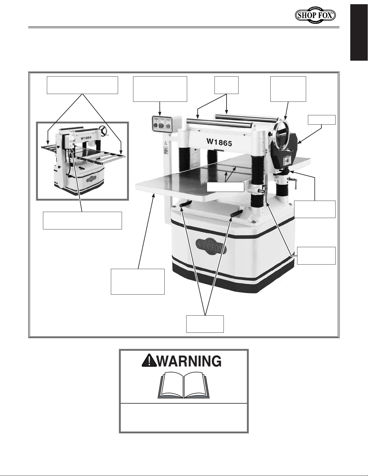
Become familiar with the names and locations of the controls and features shown below to better
Identification
INTRODUCTION
Roller Extension Tables
(W1864)
Magnetic ON/OFF Switch
(W1864)
Control Panel for
Magnetic Switch
(W1865)
Return
Rollers
Bed Rollers
Table
Height
Handwheel
Gearbox
Feed Rate
Control Knob
Table Locks
(1 of 2)
Cast-Iron
Extension Tables
(W1865)
Lifting Bars
(2 of 4)
To reduce your risk of serious injury
or damage to the machine, read this
entire manual BEFORE using machine.
-7-
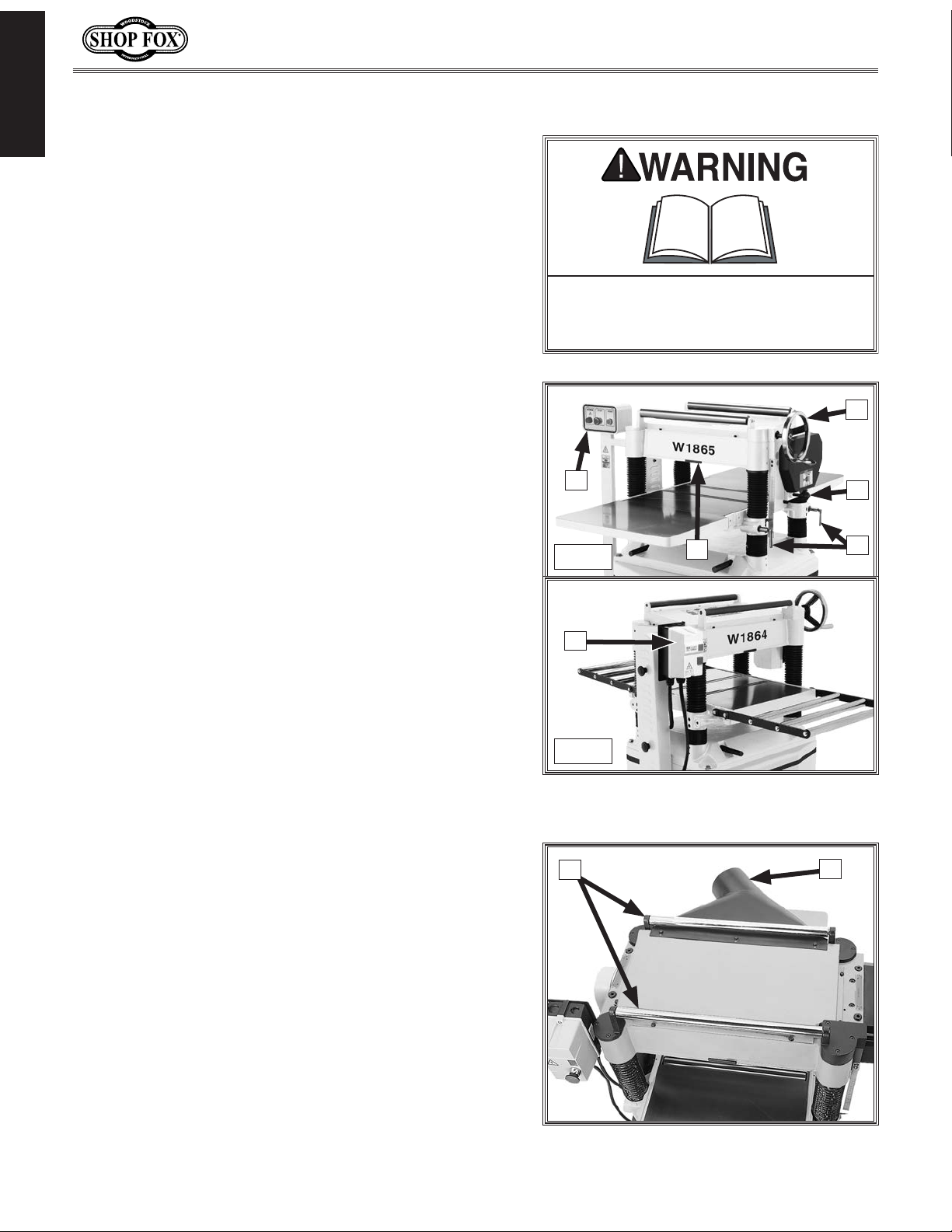
Controls & Components
Refer to the Figures 1–2 and the following descriptions to
INTRODUCTION
become familiar with the basic controls and components
of this machine. Understanding these items and how they
work will help you understand the rest of the manual and
stay safe when operating this machine.
A. Control Panel for Magnetic Switch (W1865):
— Green START button turns motor ON.
— Power indicator light illuminates when motor is
turned ON.
— Red STOP button turns motor OFF; for safety
purposes, this button remains depressed and
prevents restarting until reset. Reset by rotating
clockwise until it pops out.
B. Table Height Handwheel: Raises and lowers table to
accommodate different workpiece thicknesses. One
complete revolution of handwheel moves the table
approximately
1
⁄16".
Model W1864/W1865 (For Machines Mfd. Since 02/19)
To reduce your risk of serious injury
or damage to the machine, read this
entire manual BEFORE using machine.
B
A
C
C. Feed Rate Control Knob: Selects 28 FPM feed rate
when pushed in and 16 FPM feed rate when pulled
out.
D. Table Locks: Secure table height position so they
don't shift during cutting operation.
E. Depth Limiter: Limits depth of cut to a maximum of
1
⁄8" at full width.
F. Magnetic ON/OFF Switch (W1864):
— Green START button turns motor ON.
— Red STOP button turns motor OFF; for safety
purposes, this button remains depressed and
prevents restarting until reset. Reset by rotating
clockwise until it pops out.
G. Return Rollers: Assist sliding workpiece back to
operator following planing operation.
H. Dust Port: 5" dust port connects to a dust-collection
system to extract shavings and dust during
operation.
W1865
F
W1864
Figure 1. Table elevation and feed
G
E
controls.
D
H
-8-
Figure 2. Example of return rollers and
dust port.

Model W1864/W1865 (For Machines Mfd. Since 02/19)
Internal Components
Front Rear
C
D
E
F
INTRODUCTION
A
Figure 3. Workpiece path and major planing components (side cutaway view).
A. Anti-Kickback Fingers: Provide additional
safety for the operator.
B. Serrated Infeed Roller: Pulls the workpiece
toward the cutterhead.
C. Chip Breaker: Breaks off chips created by
the cutterhead to prevent tear-out and
diverts the chips to the dust hood.
D. Chip Deflector: Directs chips into the dust
hood.
E. Cutterhead: Holds the knives/indexable
carbide inserts that remove material from
the workpiece.
B
Workpiece
H
G
I
F. Pressure Bar: Stabilizes the workpiece
as it leaves the cutterhead and assists in
deflecting wood particles toward the dust
hood.
G. Outfeed Roller: Pulls the workpiece
through the planer.
H. Bed Rollers: Provide upward pressure on
the workpiece, enabling the feed rollers to
pull the workpiece along.
I. Planer Table: Provides a smooth and level
path for the workpiece as it moves through
the planer.
H
Like all machinery there is potential danger when operating this machine. Accidents are frequently caused by lack of familiarity or failure to pay attention. Use this machine with respect
and caution to decrease the risk of operator injury. If normal safety precautions are overlooked
or ignored, serious personal injury may occur.
-9-

Model W1864/W1865 (For Machines Mfd. Since 02/19)
SAFETY
OWNER’S MANUAL.
TRAINED OPERATORS ONLY.
DANGEROUS ENVIRONMENTS.
MENTAL ALERTNESS REQUIRED.
electrical components or improperly grounded
manual uses a series of symbols and signal words intended to convey the level of importance of the
safety messages. The progression of symbols is described below. Remember that safety messages by
SAFETY
For Your Own Safety,
Read Manual Before Operating Machine
The purpose of safety symbols is to attract your attention to possible hazardous conditions. This
SAFETY
themselves do not eliminate danger and are not a substitute for proper accident prevention measures—this responsibility is ultimately up to the operator!
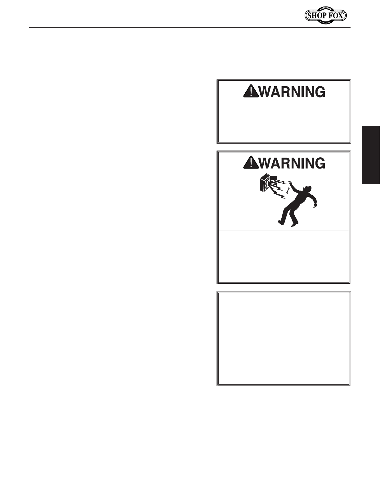
NOTICE
Standard Machinery Safety Instructions
Standard Machinery Safety Instructions
Indicates an imminently hazardous situation which, if not avoided,
WILL result in death or serious injury.
Indicates a potentially hazardous situation which, if not avoided,
COULD result in death or serious injury.
Indicates a potentially hazardous situation which, if not avoided,
MAY result in minor or moderate injury.
This symbol is used to alert the user to useful information about
proper operation of the equipment or a situation that may cause
damage to the machinery.
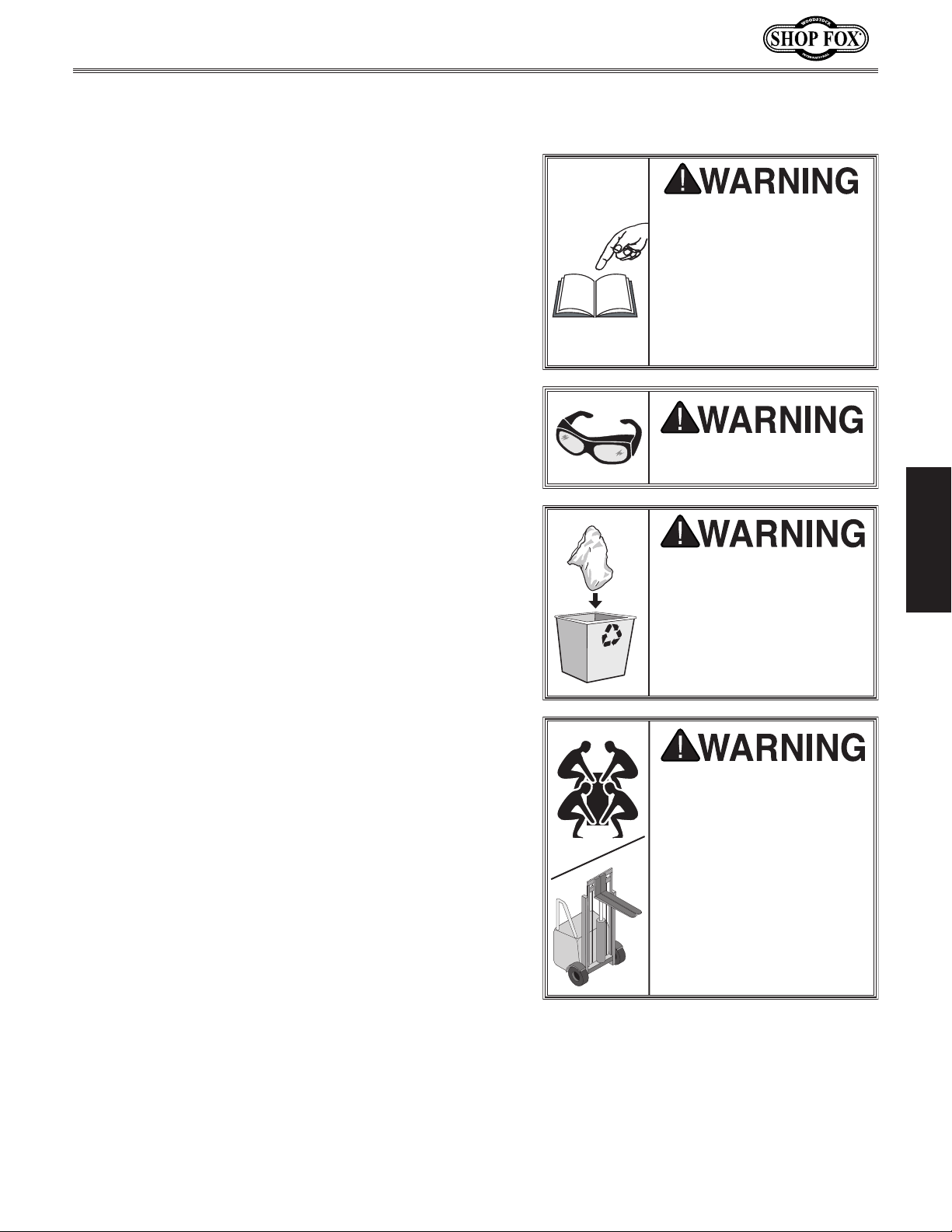
Read and understand this
owner’s manual BEFORE using machine.
have a higher risk of being hurt or killed. Only
allow trained/supervised people to use this
machine. When machine is not being used,
disconnect power, remove switch keys, or
lock-out machine to prevent unauthorized
use—especially around children. Make
workshop kid proof!
machinery in areas that are wet, cluttered,
or have poor lighting. Operating machinery
in these areas greatly increases the risk of
accidents and injury.
alertness is required for safe operation of
machinery. Never operate under the influence
of drugs or alcohol, when tired, or when
distracted.
Untrained operators
Do not use
Full mental
ELECTRICAL EQUIPMENT INJURY RISKS. You can
be shocked, burned, or killed by touching live
machinery. To reduce this risk, only allow an
electrician or qualified service personnel to
do electrical installation or repair work, and
always disconnect power before accessing or
exposing electrical equipment.
DISCONNECT POWER FIRST. Always disconnect
machine from power supply BEFORE making
adjustments, changing tooling, or servicing
machine. This eliminates the risk of injury
from unintended startup or contact with live
electrical components.
EYE PROTECTION. Always wear ANSI-approved
safety glasses or a face shield when operating
or observing machinery to reduce the risk of
eye injury or blindness from flying particles.
Everyday eyeglasses are not approved safety
glasses.
-10-

Model W1864/W1865 (For Machines Mfd. Since 02/19)
WEARING PROPER APPAREL. Do not wear
HAZARDOUS
HEARING PROTECTION.
REMOVE ADJUSTING TOOLS.
INTENDED USAGE.
AWKWARD POSITIONS.
CHILDREN & BYSTANDERS.
GUARDS & COVERS.
FORCING MACHINERY. Do not force machine. It
will do the job safer and better at the rate for
loss of control. Before starting, verify machine
malfunction, leading to serious personal injury
from heated surfaces, high traffic areas, harsh
clothing, apparel, or jewelry that can become
entangled in moving parts. Always tie back
or cover long hair. Wear non-slip footwear to
avoid accidental slips, which could cause loss
of workpiece control.
DUST. Dust created while using
machinery may cause cancer, birth defects,
or long-term respiratory damage. Be aware of
dust hazards associated with each workpiece
material, and always wear a NIOSH-approved
respirator to reduce your risk.
Always wear hearing
protection when operating or observing
loud machinery. Extended exposure to this
noise without hearing protection can cause
permanent hearing loss.
machinery can become dangerous projectiles
upon startup. Never leave chuck keys,
wrenches, or any other tools on machine.
Always verify removal before starting!
intended purpose—never make modifications
without prior approval from Woodstock
International. Modifying machine or using
it differently than intended will void the
warranty and may result in malfunction or
mechanical failure that leads to serious
personal injury or death!
balance at all times when operating machine.
Do not overreach! Avoid awkward hand
positions that make workpiece control difficult
or increase the risk of accidental injury.
bystanders at a safe distance from the work
area. Stop using machine if they become a
distraction.
Only use machine for its
Tools left on
Keep proper footing and
Keep children and
which it was designed.
NEVER STAND ON MACHINE. Serious injury may
occur if machine is tipped or if the cutting
tool is unintentionally contacted.
STABLE MACHINE. Unexpected movement during
operation greatly increases risk of injury or
is stable and mobile base (if used) is locked.
USE RECOMMENDED ACCESSORIES. Consult
this owner’s manual or the manufacturer for
recommended accessories. Using improper
accessories will increase risk of serious injury.
UNATTENDED OPERATION. To reduce the risk
of accidental injury, turn machine OFF and
ensure all moving parts completely stop
before walking away. Never leave machine
running while unattended.
MAINTAIN WITH CARE. Follow all maintenance
instructions and lubrication schedules to
keep machine in good working condition. A
machine that is improperly maintained could
or death.
CHECK DAMAGED PARTS. Regularly inspect
machine for any condition that may affect
safe operation. Immediately repair or replace
damaged or mis-adjusted parts before
operating machine.
MAINTAIN POWER CORDS. When disconnecting
cord-connected machines from power, grab
and pull the plug—NOT the cord. Pulling the
cord may damage the wires inside, resulting
in a short. Do not handle cord/plug with wet
hands. Avoid cord damage by keeping it away
chemicals, and wet/damp locations.
SAFETY
accidental contact with moving parts or flying
debris—make sure they are properly installed,
undamaged, and working correctly.
Guards and covers reduce
EXPERIENCING DIFFICULTIES. If at any time
you experience difficulties performing the
intended operation, stop using the machine!
-11-
Contact Technical Support at (360) 734-3482.

Model W1864/W1865 (For Machines Mfd. Since 02/19)
Amputation, serious cuts, entanglement, or death can occur from contact with rotating cutterhead
KICKBACK.
AVOID CONTACT WITH MOVING PARTS.
DULL/DAMAGED KNIVES/INSERTS.
INSPECTING STOCK.
BODY PLACEMENT.
GRAIN DIRECTION.
angle with the wood grain.
To reduce the risk
of kickback, never start planer with workpiece
Additional Safety for Planers
or other moving parts! Flying chips can cause eye injuries or blindness. Workpieces or knives
thrown by cutterhead can strike nearby operator or bystanders with deadly force. To reduce risk
of these hazards, operator and bystanders MUST completely heed hazards and warnings below.
SAFETY
kickback and kickback-related injuries.
“Kickback” occurs during operation when
the workpiece is ejected from the machine
at high speed. Kickback is commonly caused
by poor workpiece selection, unsafe feeding
techniques, or improper machine setup/
maintenance. Kickback injuries typically occur
as follows: (1) operator/bystanders are struck
by the workpiece, resulting in impact injuries
(i.e., blindness, broken bones, bruises, death);
(2) operator’s hands are pulled into blade,
resulting in amputation or severe lacerations.
remove guards/covers or reach inside the
planer during operation or while connected to
power. You could be seriously injured if you
accidentally touch the spinning cutterhead
or get entangled in moving parts. If a
workpiece becomes stuck or sawdust removal
is necessary, turn planer OFF and disconnect
power before clearing.
sharp, undamaged knives/inserts. Dull or
damaged knives/inserts increase the risk of
kickback.
Know how to reduce the risk of
Never
Only use
PLANING CORRECT MATERIAL. Only plane
natural wood stock with this planer. DO NOT
plane MDF, OSB, plywood, laminates or other
synthetic materials that can break up inside
the planer and be ejected towards operator.
LOOKING INSIDE PLANER. Wood chips fly around
inside the planer at a high rate of speed
during operation. To avoid injury from flying
material, DO NOT look inside planer during
operation.
CUTTING LIMITATIONS. To reduce the risk of
kickback hazards or damage to the machine,
do not exceed the maximum depth of cut or
minimum board length and thickness found
in the Data Sheet. Only feed one board at a
time.
INFEED ROLLER CLEARANCE. The infeed
roller is designed to pull material into the
spinning cutterhead. To reduce the risk of
entanglement, keep hands, clothing, jewelry,
and long hair away from the infeed roller
during operation.
FEED WORKPIECE PROPERLY.
kickback injuries or machine damage,
thoroughly inspect and prepare the workpiece
before cutting. Verify workpiece is free of
nails, staples, loose knots or foreign material.
Workpieces with minor warping should be
jointed first or planed with the cupped side
facing the table.
during the entire operation to avoid getting
hit if kickback occurs.
hard on the planer and may cause kickback.
Plane in the same direction or at a slight
To reduce the risk of
Stand to one side of planer
Planing across the grain is
touching cutterhead. Allow cutterhead to
reach full speed before feeding, and do not
-12-
change feed speed during cutting operation.
WORKPIECE SUPPORT. To reduce the risk of
kickback, always make sure workpiece can
move completely across table without rocking
or tipping. Use auxiliary support stands for
long stock.
SECURE KNIVES/INSERTS. Loose knives or
improperly set inserts can become dangerous
projectiles or cause machine damage. Always
verify knives/inserts are secure and properly
adjusted before operation.
Model W1864/W1865 (For Machines Mfd. Since 02/19)
This machine must be connected to the correct size and
type of power supply circuit, or fire or electrical damage
may occur. Read through this section to determine if an
adequate power supply circuit is available. If a correct
circuit is not available, a qualified electrician MUST install
one before you can connect the machine to power.
A power supply circuit includes all electrical equipment
between the breaker box or fuse panel in the building
and the machine. The power supply circuit used for
this machine must be sized to safely handle the fullload current drawn from the machine for an extended
period of time. (If this machine is connected to a circuit
protected by fuses, use a time delay fuse marked D.)
The full-load current rating is the amperage a machine
draws at 100% of the rated output power. On machines
with multiple motors, this is the amperage drawn by the
largest motor or sum of all motors and electrical devices
that might operate at one time during normal operations.
or machine damage. To reduce this risk,
a dedicated circuit—
where only one machine will be running
multiple machines will be running at the
This machine is prewired to operate on a power supply
circuit that has a verified ground and meets the following
requirements:
ELECTRICAL
Circuit Requirements
The machine must be properly set up
before it is safe to operate. DO NOT
connect this machine to the power
source until instrtucted to do so later
in this manual.
ELECTRICAL
Full-Load Current Rating
Full-Load Current Rating at 220V ................ 23 Amps
Circuit Requirements
Nominal Voltage ................. 208V, 220V, 230V, 240V
Cycle ........................................................60 Hz
Phase .................................................... 1-Phase
Power Supply Circuit ................................ 30 Amps
Plug/Receptacle ..................................NEMA L6-30
Cord .................“S”-Type, 3-Wire, 12 AWG, 300 VAC
Incorrectly wiring or grounding this
machine can cause electrocution, fire,
only an electrician or qualified service
personnel should do any required
electrical work on this machine.
NOTICE
The circuit requirements listed in this
manual apply to
at a time. If this machine will be
connected to a shared circuit where
same time, consult with an electrician
to ensure that the circuit is properly
sized for safe operation.
-13-
Model W1864/W1865 (For Machines Mfd. Since 02/19)
This machine MUST be grounded. In the event of certain
types of
a path of least resistance for electric current
order
Improper connection of the equipment-grounding
will
increase
insulation
grounding
cord or plug is necessary, do not connect the equipmentgrounding
Check with a qualified electrician or service personnel
if
or if
properly grounded.
plug is damaged or worn, disconnect it from power, and
immediately replace it with a new one.
This machine is equipped with a power cord that has an
equipment-grounding
plug.
receptacle (
grounded in accordance with local codes and ordinances.
We do not recommend using an extension cord with
this machine. Extension cords cause voltage drop, which
may damage electrical components and shorten motor
life. Voltage drop increases with longer extension cords
and smaller gauge sizes (higher gauge numbers indicate
smaller sizes).
Any extension cord used with this machine must contain a
ground wire
plug and receptacle, and
meet the following requirements:
the available receptacle or the machine
Grounding Requirements
malfunctions or breakdowns, grounding provides
to travel—in
to reduce the risk of electric shock.
wire
the risk of electric shock. The wire with green
(with/without yellow stripes) is the equipment-
wire. If repair or replacement of the power
The machine must be properly set up
before it is safe to operate. DO NOT
connect this machine to the power
source until instrtucted to do so later
in this manual.
wire to a live (current carrying) terminal.
you do not understand these grounding requirements,
you are in doubt about whether the tool is
ELECTRICAL
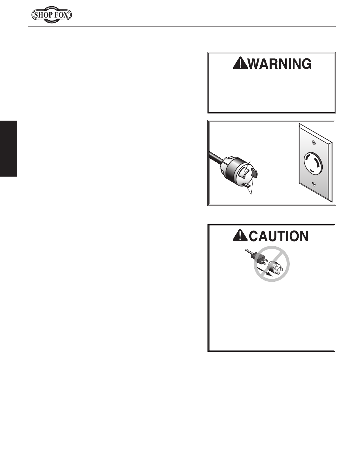
For 220V Connection
The plug must only be inserted into a matching
see Figure) that is properly installed and
Extension Cords
If you ever notice that a cord or
wire and NE M A L6-3 0 grounding
L6-30 GROUNDED
LOCKING
RECEPTACLE
Grounding Prong
is Hooked
L6-30
LOCKING
PLUG
Current Carrying Prongs
Figure 4. NEMA L6-30 plug & receptacle.
No adapter should be used with the
required plug. If the plug does not fit
Minimum Gauge Size at 230V ...................... 10 AWG
Maximum Length (Shorter is Better) ................50 ft.
, match the required
must be reconnected to a different
type of circuit, the reconnection must
be made by an electrician or qualified
service personnel and it must comply
with all local codes and ordinances.
-14-
Model W1864/W1865 (For Machines Mfd. Since 02/19)
This machine has been carefully packaged for safe
transportation. If you notice the machine has been
damaged during shipping, please contact your authorized
Shop Fox dealer immediately.
The following items are needed, but not included, to set
up your machine.
This machine presents
serious injury hazards
to untrained users. Read
to become familiar with
tions before starting the
Immediately discard all
materials to eliminate
Straining or crushing
improperly lifting the
parts. To reduce this
SETUP
Unpacking
through this entire manual
the controls and opera-
Items Needed for Setup
Description Qty
• Additional People ..........................................1
• Safety Glasses ................................ 1 Per Person
• Forklift (rated for at least 1000 lbs.) ..................1
• Cleaner/Degreaser ............................ As Needed
• Disposable Shop Rags ......................... As Needed
• Phillips Screwdriver #2 ...................................1
• Hex Wrench 6mm ..........................................1
• Wrench or Socket 18mm .................................1
• Straightedge 4' .............................................1
• Dust-Collection System ...................................1
• 5" Dust Hose ........................... Length As Needed
• 5" Hose Clamps ............................................2
W1864 Only:
• Wrench or Socket 10mm, 16mm ...................1 Ea.
W1865 Only:
• Wrench or Socket 13mm .................................1
machine!
Wear safety glasses during
entire setup process!
SETUP
SUFFOCATION HAZARD!
plastic bags and packing
choking/suffocation
hazards for children and
animals.
HEAVY LIFT!
injury may occur from
machine or some of its
risk, get help from other
people and use a forklift
(or other lifting equipment) rated for weight of
machine.
-15-
Model W1864/W1865 (For Machines Mfd. Since 02/19)
The following is a list of items shipped with your machine.
Before beginning setup, lay these items out and inventory
them.
Note:
check around/inside the machine and packaging materials.
Often, these items get lost in packaging materials while
unpacking or they are pre-installed at the factory.
Inventory
If you cannot find an item on this list, carefully
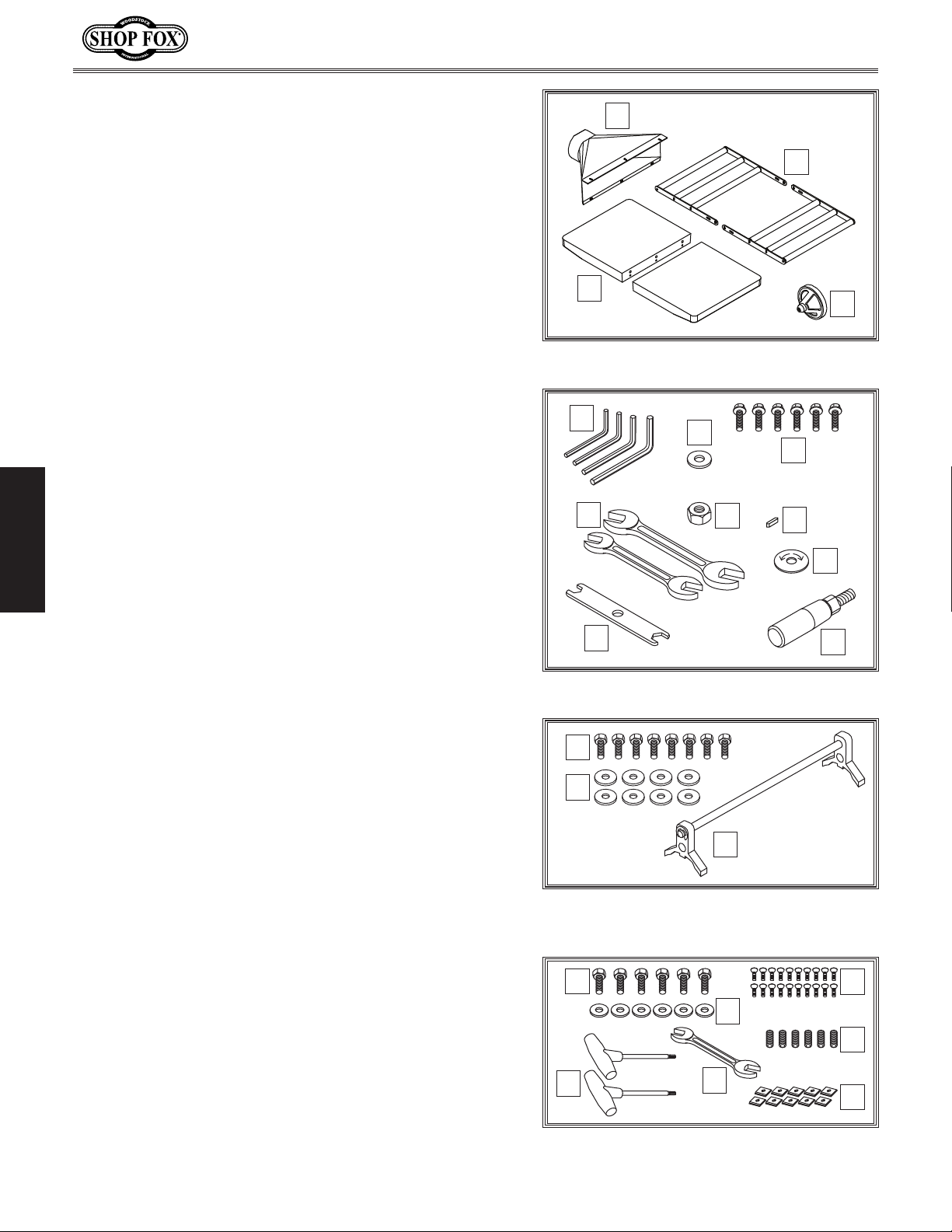
Box 1 (Figure 5) Qty
A. Planer Unit (Not Shown)..................................1
B. Dust Hood ...................................................1
C. Roller Ext. Tables (W1864) ...............................2
D. Cast-Iron Extension Tables (W1865) ....................2
E. Table Height Handwheel .................................1
Tools and Hardware (Figure 6)
F. Hex Wrenches 3, 4, 5, 6mm ........................1 Ea.
G. Flat Washer 12mm (Handwheel) ........................1
SETUP
H. Flange Bolts M6-1 x 12 (Dust Hood) ....................6
I. Key 4 x 4 x 10 (Handwheel)..............................1
J. LOW/HIGH Direction Label (Handwheel) ..............1
K. Handwheel Handle (Handwheel) ........................1
L. Flat Wrench 10/13mm ....................................1
M. Open-End Wrenches 12/14, 17/19mm ............1 Ea.
N. Hex Nut M12-1.75 (Handwheel) .........................1
B
D
Figure 5. Box inventory.
F
M
L
Figure 6. Tools and hardware.
G
N
LOW HIGH
C
E
H
I
J
K
W1864 Only (Figure 7)
O. Hex Bolts M10-1.5 x 25 (Ext. Tables) ...................8
P. Fender Washers 10mm (Ext. Tables) ...................8
Q. Knife-Setting Jig Assembly ...............................1
— Knife-Setting Jig Foot ..................................2
— Knife-Setting Jig Shaft .................................1
— E-Clip 9mm ..............................................4
W1865 Only (Figure 8)
R. Hex Bolts M8-1.25 x 25 (Ext. Tables) ...................6
S. Flat Washers 8mm (Ext. Tables) .........................6
T. Flat Head Torx Screws #10-32 x
U. Set Screws M8-1.25 x 12 (Ext. Tables) .................6
V. Indexable Carbide Inserts 15 x 15 x 2.5 ............. 10
W. Wrench 8/10mm ...........................................1
X. T-Handle Torx Wrenches T-25 ............................2
1
⁄2" .................. 20
-16-
O
P
Q
Figure 7. Tools and hardware (W1864 only).
R
S
X
Figure 8. Tools and hardware (W1865
W
only).
T
U
V
Model W1864/W1865 (For Machines Mfd. Since 02/19)
To prevent
machine, the factory has coated t
of your machine
compound
I
be difficult to
coating is as easy as possible, please gather the correct
cleaner, lubricant, and tools listed below:
• Cleaner/degreaser
and grease
• Safety glasses & disposable gloves
•
• Disposable Rags
To
1.
2.
3
4
5
6
immediately coat with a quality metal protectant.
Cleaning Machine
corrosion during shipment and storage of your
with a heavy-duty rust prevention
.
f you are unprepared or impatient, this compound can
remove. To ensure that the removal of this
designed to remove storage wax
Solvent brush or paint brush
remove rust preventative coating, do these steps:
DISCONNECT MACHINE FROM POWER!
he bare metal surfaces
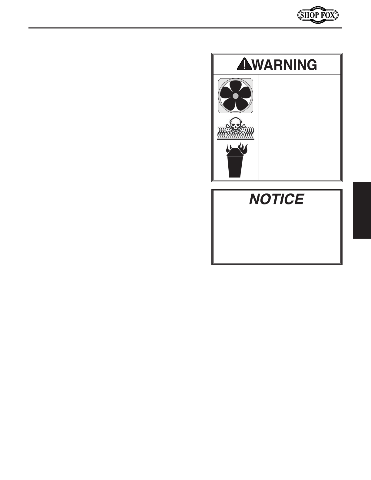
Gasoline and petroleum
products have low flash
points and can explode
or cause fire if used to
clean machinery. Avoid
using these products
to clean machinery.
Many cleaning solvents
are toxic if inhaled.
Minimize your risk
by only using these
products in a well
ventilated area.
SETUP
Put on safety glasses and disposable gloves.
. Coat the rust preventative with a liberal amount of
cleaner/degreaser, then let it soak for 5–10 minutes.
. Wipe off surfaces. If your cleaner/degreaser is
effective, the coating will wipe off easily.
Tip: An easier way to clean off thick coats of rust
preventative from flat surfaces is to use a PLASTIC
paint scraper to scrape off the majority of the
coating before wiping it off with your rag. (Do
not use a metal scraper or you may scratch your
machine.)
. Repeat cleaning steps as necessary until all of the
compound is removed.
. To prevent rust on freshly cleaned surfaces,
In a pinch, automotive degreasers,
mineral spirits or WD•40 can be used
to remove rust preventative coating.
Before using these products, though,
test them on an inconspicuous area of
your paint to make sure they will not
damage it.
-17-
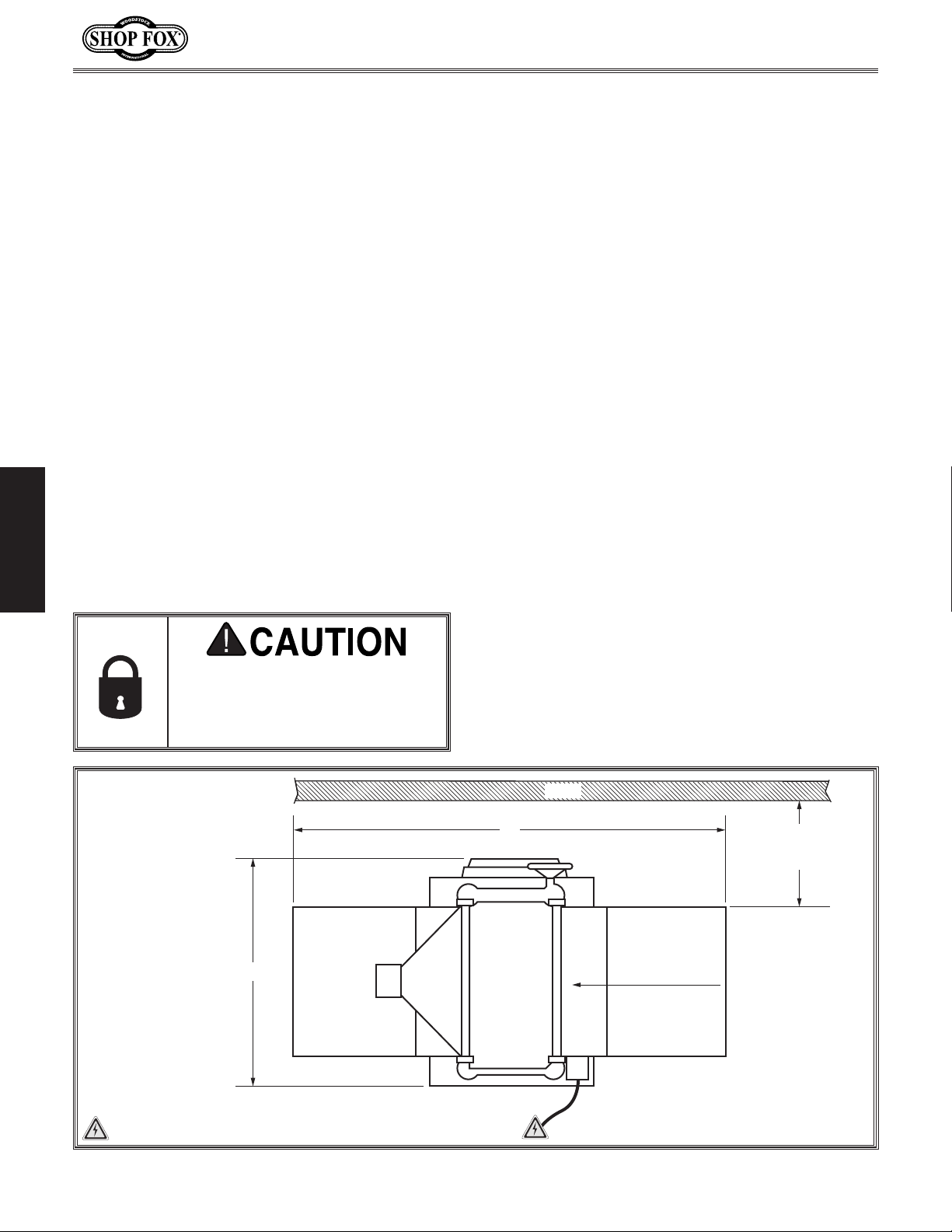
Machine Placement
Weight Load
Refer to the
weight of your machine. Make sure that the
surface upon which the machine is placed will
bear the weight of the machine, additional
equipment that may be installed on the
machine, and the heaviest workpiece that will
be used. Additionally, consider the weight of
the operator and any dynamic loading that may
occur when operating the machine.
Space Allocation
Consider the largest size of workpiece that
will be processed through this machine and
provide enough space around the machine
for adequate operator material handling or
the installation of auxiliary equipment. With
permanent installations, leave enough space
around the machine to open or remove doors/
covers as required by the maintenance and
service described in this manual.
required space allocation.
Physical Environment
The physical environment where your machine is
operated is important for safe operation and the
ambient temperature range exceeds 41°–104°F;
(non-condensing); or the environment is subject
source. Make sure all power cords are protected
chemicals, or other hazards. Make sure to leave
Machine Specifications for the
Model W1864/W1865 (For Machines Mfd. Since 02/19)
longevity of its components. For best results,
operate this machine in a dry environment
that is free from excessive moisture, hazardous
chemicals, airborne abrasives, or extreme
conditions. Extreme conditions for this type
of machinery are generally those where the
the relative humidity range exceeds 20–95%
to vibration, shocks, or bumps.
Electrical Installation
Place this machine near an existing power
SETUP
See below for
Children or untrained people
may be seriously injured by this
machine. Only install in an access
restricted location.
Model W1864
X = 58"
Y = 39"
Y
Port
Model W1865
X = 56"
Y = 39"
from traffic, material handling, moisture,
access to a means of disconnecting the power
source or engaging a lockout/tagout device.
Lighting
Lighting around the machine must be adequate
enough that operations can be performed
safely. Shadows, glare, or strobe effects that
may distract or impede the operator must be
eliminated.
Wall
X
Feed DirectionDust
Min. 30"
for Maintenance
= Electrical Connection
Figure 9. Working clearances.
-18-
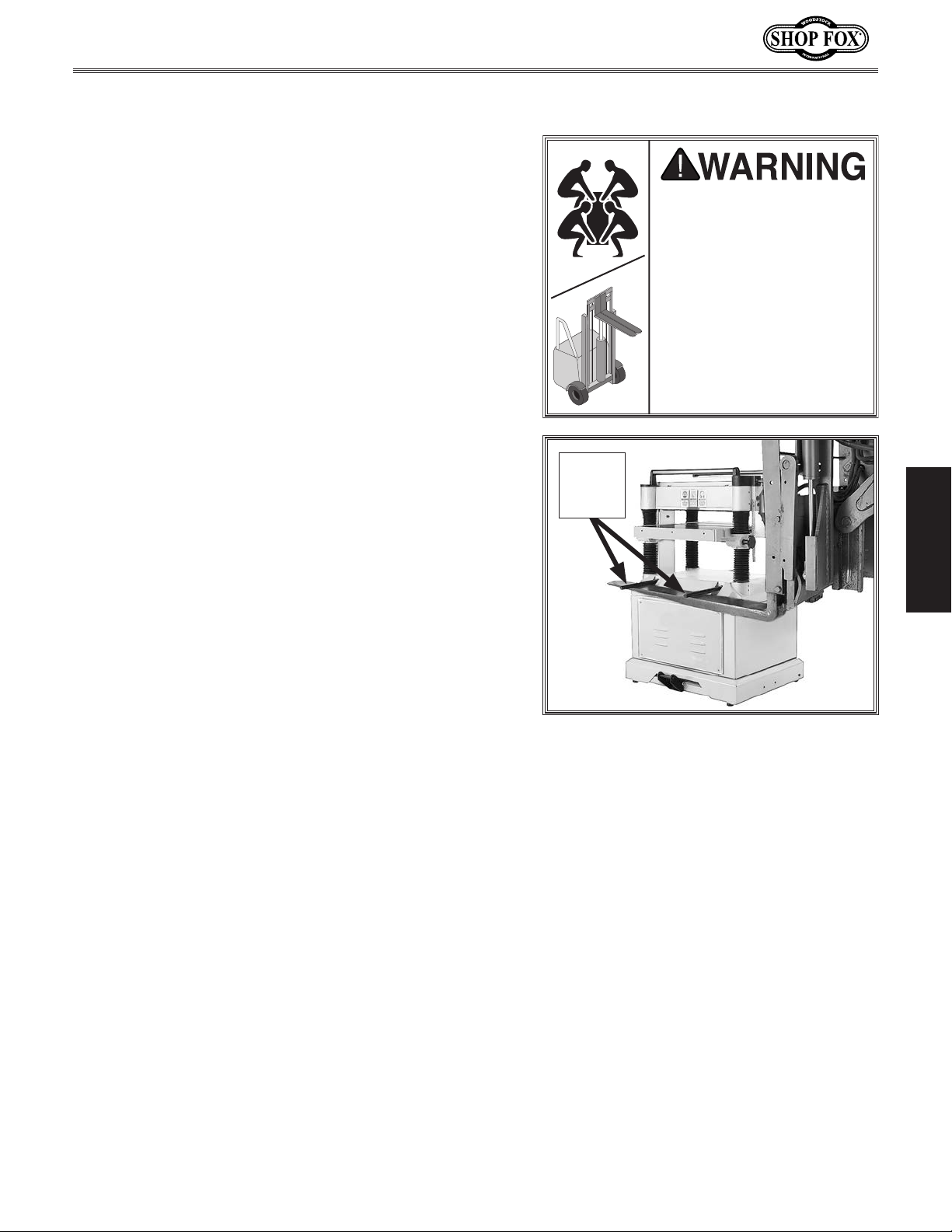
Model W1864/W1865 (For Machines Mfd. Since 02/19)
Straining or crushing
improperly lifting the
parts. To reduce this
Lifting & Moving
The planer is equipped with four lifting bars that extend
in order to lift and place the planer.
To lift and place the planer, extend the lifting bars and
use a forklift to lift the machine off the pallet, as shown
in Figure 10, then set the planer down in a suitable
location and return the lifting bars to their original
position.
Tip: When positioning lift forks, place shop rags or
cardboard between forks and cabinet stand to avoid
scratching paint.
Lifting
Bars
(2 of 4)
HEAVY LIFT!
injury may occur from
machine or some of its
risk, get help from other
people and use a forklift
(or other lifting equipment) rated for weight of
machine.
SETUP
Figure 10. Example of lifting planer with
forklift.
-19-
Assembly
Before beginning the assembly process, refer to Items
Needed for Setup
Ensure all parts have been properly cleaned of any
heavy-duty rust-preventative applied at the factory (if
applicable). Be sure to complete all steps in the assembly
procedure prior to performing the Test Run or connecting
and gather everything you need.
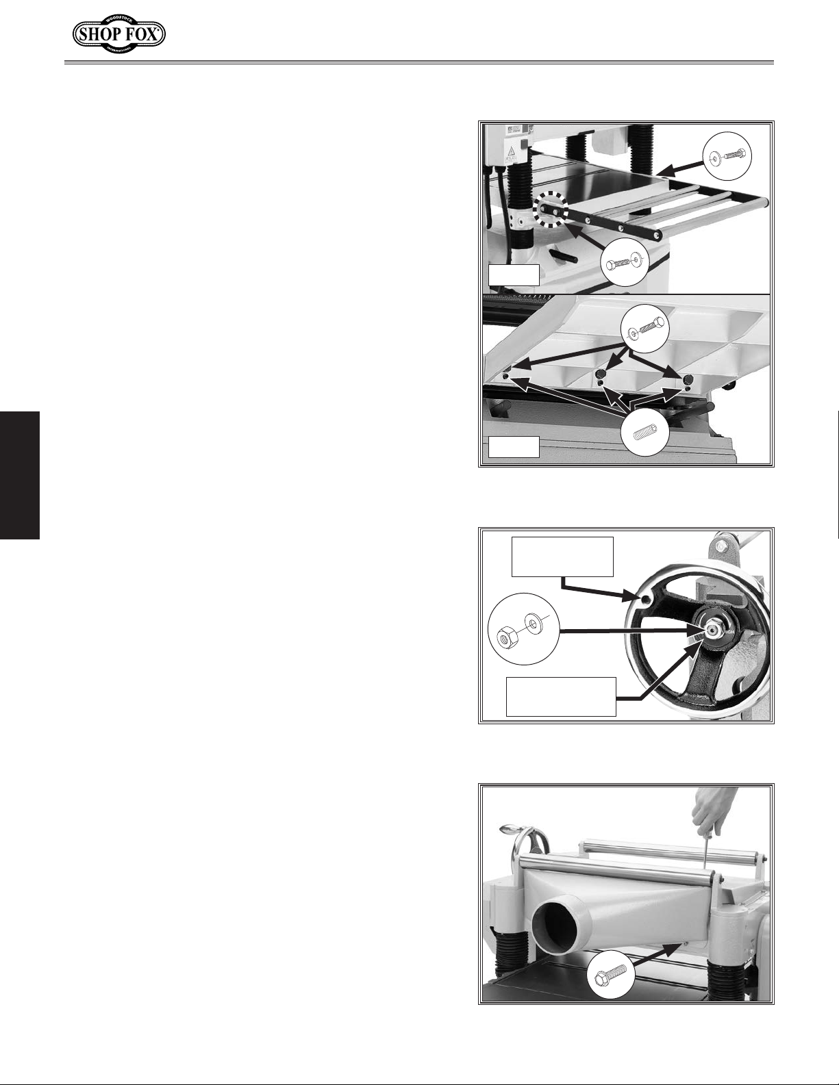
To assemble planer, do these steps:
1. W1864: Attach each roller extension table to planer
table with (4) M10-1.5 x 25 hex bolts and (4) 10mm
fender washers (see Figure 11). Do not fully tighten
hex bolts at this time.
W1865: Attach each cast-iron extension table to
planer table with (3) M8-1.25 x 25 hex bolts and (3)
8mm flat washers (see Figure 11). Do not tighten
hex bolts at this time.
2. W1865: Thread (3) M8-1.25 x 20 set screws into each
extension table at locations shown in Figure 11.
SETUP
3. W1864: Using a straightedge as a guide, position
extension tables so they are in plane with main
table, then fully tighten hex bolts from Step 1.
Model W1864/W1865 (For Machines Mfd. Since 02/19)
x 2
W1864
W1865
Figure 11. Extension table mounting
Install Handle
Here
x 2
x 3
x 3
locations.
W1865: Using a straightedge as a guide, rotate set
screws from Step 2 until extension tables are in
plane with main table, then fully tighten hex bolts
from Step 1.
Note: Bed rollers will give you a false reading
with your straightedge if they are raised above
table. Move them down or work around them when
leveling extension wings (refer to Bed Roller Height
on Page 29 for details).
4. Insert key into keyway on handwheel shaft on top of
planer.
5. Line up notch in handwheel bore with key, then slide
handwheel onto shaft (see Figure 12).
6. Slide LOW/HIGH direction label onto handwheel
shaft, and secure handwheel with 12mm flat washer
and M12-1.75 hex nut (see Figure 12).
7. Thread handwheel handle into handwheel (see
Figure 12), and tighten with wrench.
8. Attach dust hood to planer with (6) M6-1 x 12 flange
bolts (see Figure 13).
x 1
LOW/HIGH
Direction Label
Figure 12. Table elevation handwheel
installed.
x 6
Figure 13. Dust port installed.
-20-
Model W1864/W1865 (For Machines Mfd. Since 02/19)
Do not confuse this CFM recommendation with the rating
of the dust collector. To determine the CFM at the dust
port, you must consider these variables: (1) CFM rating of
the dust collector, (2) hose type and length between the
dust collector and the machine, (3) number of branches
or wyes, and (4) amount of other open lines throughout
the system. Explaining how to calculate these variables
is beyond the scope of this manual. Consult an expert or
purchase a good dust collection “how-to” book.
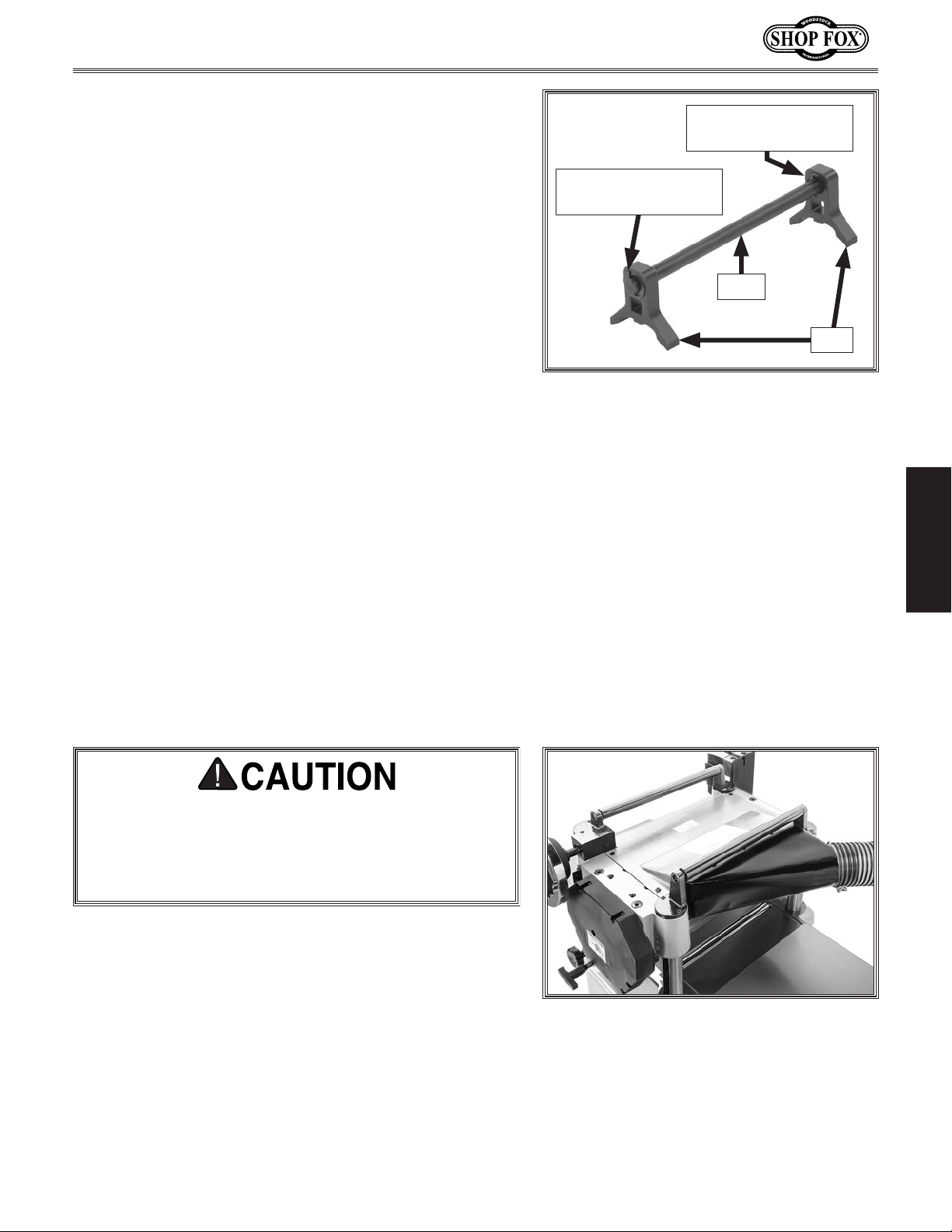
9. W1864: Assemble knife-setting jig (see Figure 14).
a. Snap (2) 9mm E-clips into inner notches on knife-
setting jig shaft.
b. Slide (2) knife-setting jig feet onto ends of shaft.
c. Snap (2) 9mm E-clips into outer notches on ends
of shaft to secure feet.
Dust Collection
Recommended CFM at Dust Port: ................ 600 CFM
E-Clip Snapped Into
Inner Notch (1 of 2)
E-Clip Snapped Into
Outer Notch (1 of 2)
Shaft
Feet
Figure 14. Example of assembled knife-
setting jig components.
SETUP
This machine creates substantial amounts of dust
during operation. Breathing airborne dust on a regular basis can result in permanent respiratory illness.
Reduce your risk by wearing a respirator and capturing the dust with a dust collection system.
To connect the machine to a dust-collection system, fit a
5" dust hose over the dust port, and secure in place with
a hose clamp (see Figure 15). Tug the hose to make sure
it does not come off.
Note: A tight fit is necessary for proper performance.
Figure 15. Example of dust hose
connected to dust port.
-21-
 Loading...