

Page 1

MODEL W1844
WALL-MOUNT DUST COLLECTOR
W/CANISTER FILTER
OWNER'S MANUAL
(FOR MODELS MANUFACTURED SINCE 5/17)
Phone: (360) 734-3482 • Online Technical Support: techsupport@woodstockint.com
COPYRIGHT © AUGUST, 2017 BY WOODSTOCK INTERNATIONAL, INC.
WARNING: NO PORTION OF THIS MANUAL MAY BE REPRODUCED IN ANY SHAPE OR FORM WITHOUT
THE WRITTEN APPROVAL OF WOODSTOCK INTERNATIONAL, INC.
#19009JH Printed in Taiwan
Page 2

This manual provides critical safety instructions on the proper setup,
operation, maintenance, and service of this machine/tool. Save this
document, refer to it often, and use it to instruct other operators.
Failure to read, understand and follow the instructions in this manual
may result in fire or serious personal injury—including amputation,
electrocution, or death.
The owner of this machine/tool is solely responsible for its safe use.
This responsibility includes but is not limited to proper installation in
a safe environment, personnel training and usage authorization,
proper inspection and maintenance, manual availability and comprehension, application of safety devices, cutting/sanding/grinding tool
integrity, and the usage of personal protective equipment.
The manufacturer will not be held liable for injury or property
damage from negligence, improper training, machine modifications or
misuse.
Some dust created by power sanding, sawing, grinding, drilling, and
other construction activities contains chemicals known to the State of
California to cause cancer, birth defects or other reproductive harm.
Some examples of these chemicals are:
• Lead from lead-based paints.
• Crystalline silica from bricks, cement and other masonry products.
• Arsenic and chromium from chemically-treated lumber.
Your risk from these exposures varies, depending on how often you
do this type of work. To reduce your exposure to these chemicals:
Work in a well ventilated area, and work with approved safety equipment, such as those dust masks that are specially designed to filter
out microscopic particles.
Page 3

Contents
INTRODUCTION .....................................2
Woodstock Technical Support .................. 2
Machine Specifications .......................... 3
SAFETY ............................................... 6
Standard Machinery Safety Instructions ...... 6
Additional Safety for Dust Collectors ......... 8
ELECTRICAL .........................................9
Circuit Requirements ............................9
Grounding Requirements ...................... 10
Extension Cords ................................ 10
Converting Voltage to 240V .................. 11
SETUP .............................................. 12
Unpacking ....................................... 12
Items Needed for Setup ....................... 12
Unpacking ....................................... 13
Inventory ........................................ 13
Hardware Recognition Chart ................. 14
Machine Placement ............................ 15
Assembly ......................................... 16
Dust Collection System ........................ 17
Test Run .......................................... 19
OPERATIONS....................................... 20
General .......................................... 20
Machine Storage ................................ 20
ACCESSORIES ...................................... 21
MAINTENANCE .................................... 22
General .......................................... 22
Cleaning & Protecting ......................... 22
Cleaning Canister Filter ....................... 23
Replacing Bags .................................. 23
SERVICE ............................................ 24
General .......................................... 24
Tightening Impeller ............................ 24
Troubleshooting ................................. 25
Electrical Safety Instructions ................. 27
Wiring Diagram ................................. 28
PARTS .............................................. 29
Main .............................................. 29
WARRANTY ........................................ 33
SAFETYINTRODUCTION
SET UPELECTRICAL MAINTENANCE
OPERATIONS
SERVICE PARTS
USE THE QUICK GUIDE PAGE LABELS TO SEARCH OUT INFORMATION FAST!
Page 4

Model W1844 (For Machines Mfd. Since 5/17)
INTRODUCTION
INTRODUCTION
Woodstock Technical Support
This machine has been specially designed to provide many years of trouble-free service. Close attention
to detail, ruggedly built parts and a rigid quality control program assure safe and reliable operation.
Woodstock International, Inc. is committed to customer satisfaction. Our intent with this manual is to
include the basic information for safety, setup, operation, maintenance, and service of this product.
We stand behind our machines! In the event that questions arise about your machine, please contact
Woodstock International Technical Support at (360) 734-3482 or send e-mail to: tech-support@shopfox.
biz. Our knowledgeable staff will help you troubleshoot problems and process warranty claims.
If you need the latest edition of this manual, you can download it from http://www.shopfox.biz.
If you have comments about this manual, please contact us at:
Woodstock International, Inc.
Attn: Technical Documentation Manager
P.O. Box 2309
Bellingham, WA 98227
Email: manuals@woodstockint.com
-2-
Page 5

Model W1844 (For Machines Mfd. Since 5/17)
MODEL W1844
WALLMOUNT DUST COLLECTOR WITH CANISTER FILTER
Product Dimensions
Weight........................................................................................................... 62 lbs.
Width (side‐to‐side) x Depth (front‐to‐back) x Height................................... 19‐1/2 x 22 x 46 in.
Footprint (Length x Width).............................................................................. 14 x 14 in.
Shipping Dimensions
Carton #1
Type............................................................................................. Cardboard Box
Content................................................................................................. Machine
Weight.................................................................................................... 50 lbs.
Length x Width x Height..................................................................... 20 x 22 x 19 in.
Carton #2
Type............................................................................................. Cardboard Box
Content......................................................................................... Canister Filter
Weight.................................................................................................... 14 lbs.
Length x Width x Height..................................................................... 16 x 16 x 20 in.
Electrical
Power Requirement.......................................................... 120V or 240V, Single‐Phase, 60 Hz
Prewired Voltage................................................................................................. 120V
Full‐Load Current Rating............................................................... 7A at 120V, 3.5A at 240V
Minimum Circuit Size................................................................... 15A at 120V, 15A at 240V
Connection Type......................................................................................... Cord & Plug
Power Cord Included.............................................................................................. Yes
Power Cord Length............................................................................................... 6 ft.
Power Cord Gauge............................................................................................ 16 AWG
Plug Included....................................................................................................... Yes
Included Plug Type.................................................................................... 5‐15 for 120V
Recommended Plug Type............................................................................. 6‐15 for 240V
Switch Type............................................................ Paddle Safety Switch w/Removable Key
INTRODUCTION
Motors
Main
Horsepower................................................................................................. 1 HP
Phase.............................................................................................. Single‐Phase
Amps.................................................................................................... 7A/3.5A
Speed.................................................................................................. 3450 RPM
Type......................................................................... TEFC Capacitor‐Start Induction
Power Transfer .......................................................................................... Direct
Bearings................................................................. Sealed & Permanently Lubricated
-3-
Page 6

INTRODUCTION
Model W1844 (For Machines Mfd. Since 5/17)
Main Specifications
Operation
Dust Collector Type.............................................................................. Single‐Stage
Approved Dust Types.................................................................................... Wood
Filter Type...................................................................................... Canister Filter
Airflow Performance................................................................................. 537 CFM
Max Static Pressure (at 0 CFM)........................................................................ 7.2 in.
Main Inlet Size............................................................................................. 4 in.
Inlet Adapter Included...................................................................................... No
Machine Collection Capacity At One Time................................................................. 1
Maximum Material Collection Capacity......................................................... 1.5 cu. ft.
Filtration Rating...................................................................................... 1 Micron
Bag Information
Number of Upper Bags........................................................................................ 1
Upper Bag Diameter................................................................................ 14‐1/2 in.
Upper Bag Length........................................................................................ 12 in.
Canister Information
Number of Canister Filters................................................................................... 1
Canister Filter Diameter................................................................................ 15 in.
Canister Filter Length............................................................................ 16‐3/16 in.
Impeller Information
Impeller Type........................................................................................ Radial Fin
Impeller Size.............................................................................................. 10 in.
Impeller Blade Thickness............................................................................. 3/32 in.
Construction
Upper Bag................................................................................................. Fabric
Base.......................................................................................... Steel Sheet Metal
Impeller............................................................................ Balanced Cast Aluminum
Paint Type/Finish............................................................................. Powder Coated
Blower Housing............................................................................. Steel Sheet Metal
Body......................................................................................... Steel Sheet Metal
Other
Country of Origin ............................................................................................. Taiwan
Warranty ....................................................................................................... 2 Years
Approximate Assembly & Setup Time ...................................................................... 1 Hour
Serial Number Location ............................................................. ID Label on Blower Housing
ISO 9001 Factory .................................................................................................. Yes
Certified by a Nationally Recognized Testing Laboratory (NRTL) .......................................... No
Features
1‐Micron Canister Filtration
10" Cast Aluminum Impeller
Steel Base Plate Mounts Easily to Most Walls
White Powder‐Coated Finish
Ideal Point‐Of‐Use Dust Collector
-4-
Page 7
Model W1844 (For Machines Mfd. Since 5/17)
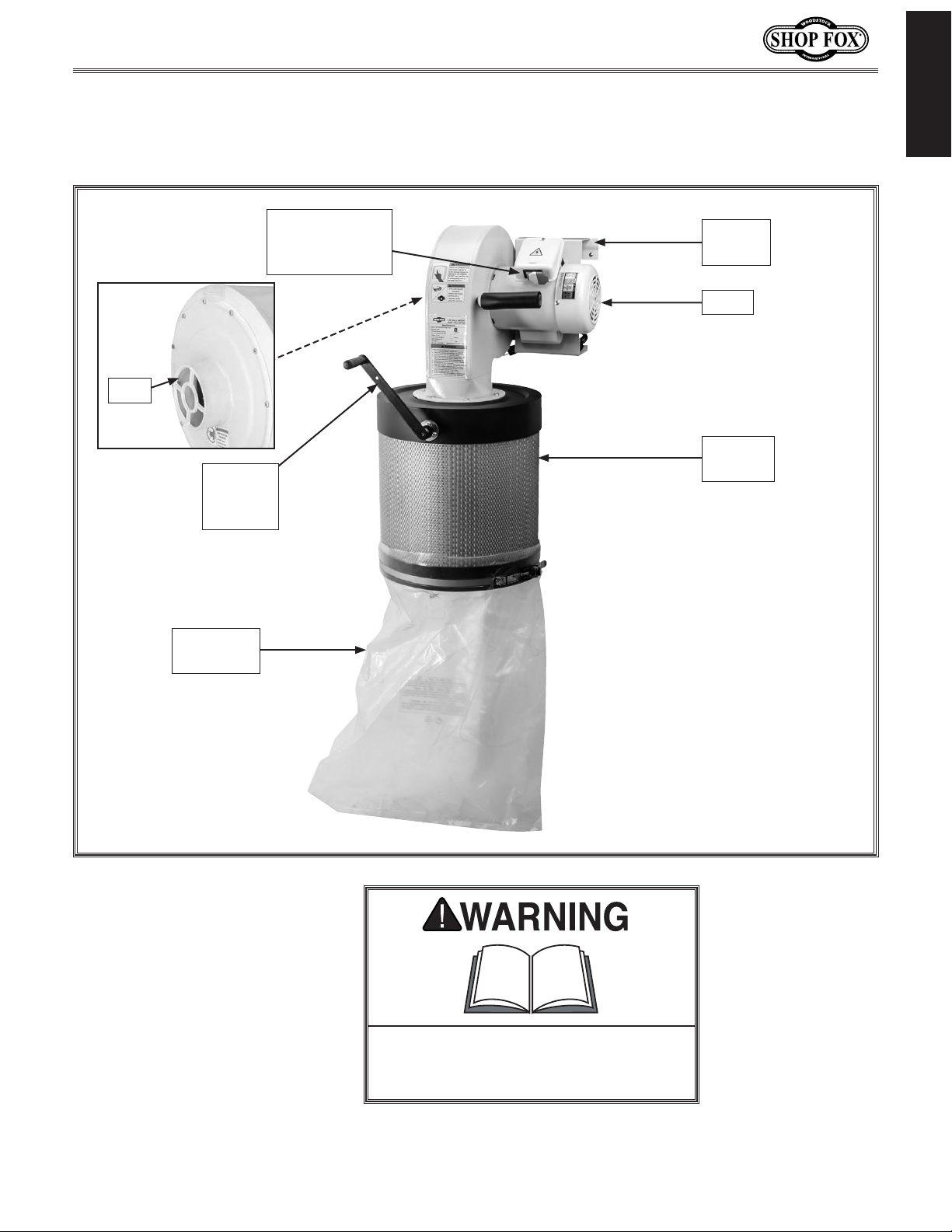
Become familiar with the names and locations of the controls and features shown below to better
Identification
INTRODUCTION
Inlet
Filter
Cleaning
Handle
Collection
Bag
Paddle Switch
w/Removable
Key
Wall
Bracket
Motor
Canister
Filter
To reduce your risk of serious injury
or damage to the machine, read this
entire manual BEFORE using machine.
-5-
Page 8

Model W1844 (For Machines Mfd. Since 5/17)
SAFETY
OWNER’S MANUAL.
TRAINED OPERATORS ONLY.
DANGEROUS ENVIRONMENTS.
MENTAL ALERTNESS REQUIRED.
electrical components or improperly grounded
manual uses a series of symbols and signal words intended to convey the level of importance of the
safety messages. The progression of symbols is described below. Remember that safety messages by
SAFETY
For Your Own Safety,
Read Manual Before Operating Machine
The purpose of safety symbols is to attract your attention to possible hazardous conditions. This
SAFETY
themselves do not eliminate danger and are not a substitute for proper accident prevention measures—this responsibility is ultimately up to the operator!
NOTICE
Standard Machinery Safety Instructions
Standard Machinery Safety Instructions
Indicates an imminently hazardous situation which, if not avoided,
WILL result in death or serious injury.
Indicates a potentially hazardous situation which, if not avoided,
COULD result in death or serious injury.
Indicates a potentially hazardous situation which, if not avoided,
MAY result in minor or moderate injury.
This symbol is used to alert the user to useful information about
proper operation of the equipment or a situation that may cause
damage to the machinery.
Read and understand this
owner’s manual BEFORE using machine.
have a higher risk of being hurt or killed. Only
allow trained/supervised people to use this
machine. When machine is not being used,
disconnect power, remove switch keys, or
lock-out machine to prevent unauthorized
use—especially around children. Make
workshop kid proof!
machinery in areas that are wet, cluttered,
or have poor lighting. Operating machinery
in these areas greatly increases the risk of
accidents and injury.
alertness is required for safe operation of
machinery. Never operate under the influence
of drugs or alcohol, when tired, or when
distracted.
Untrained operators
Do not use
Full mental
ELECTRICAL EQUIPMENT INJURY RISKS. You can
be shocked, burned, or killed by touching live
machinery. To reduce this risk, only allow an
electrician or qualified service personnel to
do electrical installation or repair work, and
always disconnect power before accessing or
exposing electrical equipment.
DISCONNECT POWER FIRST. Always disconnect
machine from power supply BEFORE making
adjustments, changing tooling, or servicing
machine. This eliminates the risk of injury
from unintended startup or contact with live
electrical components.
EYE PROTECTION. Always wear ANSI-approved
safety glasses or a face shield when operating
or observing machinery to reduce the risk of
eye injury or blindness from flying particles.
Everyday eyeglasses are not approved safety
glasses.
-6-
Page 9

Model W1844 (For Machines Mfd. Since 5/17)
WEARING PROPER APPAREL. Do not wear
HAZARDOUS
HEARING PROTECTION.
REMOVE ADJUSTING TOOLS.
INTENDED USAGE.
AWKWARD POSITIONS.
CHILDREN & BYSTANDERS.
GUARDS & COVERS.
FORCING MACHINERY. Do not force machine. It
will do the job safer and better at the rate for
loss of control. Before starting, verify machine
malfunction, leading to serious personal injury
from heated surfaces, high traffic areas, harsh
clothing, apparel, or jewelry that can become
entangled in moving parts. Always tie back
or cover long hair. Wear non-slip footwear to
avoid accidental slips, which could cause loss
of workpiece control.
DUST. Dust created while using
machinery may cause cancer, birth defects,
or long-term respiratory damage. Be aware of
dust hazards associated with each workpiece
material, and always wear a NIOSH-approved
respirator to reduce your risk.
Always wear hearing
protection when operating or observing
loud machinery. Extended exposure to this
noise without hearing protection can cause
permanent hearing loss.
machinery can become dangerous projectiles
upon startup. Never leave chuck keys,
wrenches, or any other tools on machine.
Always verify removal before starting!
intended purpose—never make modifications
without prior approval from Woodstock
International. Modifying machine or using
it differently than intended will void the
warranty and may result in malfunction or
mechanical failure that leads to serious
personal injury or death!
balance at all times when operating machine.
Do not overreach! Avoid awkward hand
positions that make workpiece control difficult
or increase the risk of accidental injury.
bystanders at a safe distance from the work
area. Stop using machine if they become a
distraction.
Only use machine for its
Tools left on
Keep proper footing and
Keep children and
which it was designed.
NEVER STAND ON MACHINE. Serious injury may
occur if machine is tipped or if the cutting
tool is unintentionally contacted.
STABLE MACHINE. Unexpected movement during
operation greatly increases risk of injury or
is stable and mobile base (if used) is locked.
USE RECOMMENDED ACCESSORIES. Consult
this owner’s manual or the manufacturer for
recommended accessories. Using improper
accessories will increase risk of serious injury.
UNATTENDED OPERATION. To reduce the risk
of accidental injury, turn machine OFF and
ensure all moving parts completely stop
before walking away. Never leave machine
running while unattended.
MAINTAIN WITH CARE. Follow all maintenance
instructions and lubrication schedules to
keep machine in good working condition. A
machine that is improperly maintained could
or death.
CHECK DAMAGED PARTS. Regularly inspect
machine for any condition that may affect
safe operation. Immediately repair or replace
damaged or mis-adjusted parts before
operating machine.
MAINTAIN POWER CORDS. When disconnecting
cord-connected machines from power, grab
and pull the plug—NOT the cord. Pulling the
cord may damage the wires inside, resulting
in a short. Do not handle cord/plug with wet
hands. Avoid cord damage by keeping it away
chemicals, and wet/damp locations.
SAFETY
accidental contact with moving parts or flying
debris—make sure they are properly installed,
undamaged, and working correctly.
Guards and covers reduce
EXPERIENCING DIFFICULTIES. If at any time
you experience difficulties performing the
intended operation, stop using the machine!
-7-
Contact Technical Support at (360) 734-3482.
Page 10

Model W1844 (For Machines Mfd. Since 5/17)
INTENDED USE. This dust collector is only
OPERATING LOCATION.
DISCONNECTING POWER SUPPLY.
IMPELLER HAZARDS.
HAZARDOUS
DUST ALLERGIES.
there is a possibility of an allergic reaction.
EMPTYING DUST. When emptying dust from
reduce this risk, thoroughly ground all plastic
Regularly check/empty the
Additional Safety for Dust Collectors
intended for collecting wood dust and chips
from woodworking machines. DO NOT use
this dust collector to collect metal, dirt,
pebbles, drywall, asbestos, lead paint,
SAFETY
silica, liquids, aerosols, or any flammable,
combustible, or hazardous materials.
To reduce respiratory
exposure to fine dust, locate permanently
installed dust collectors away from the
working area, or in another room that is
equipped with a smoke detector. DO NOT
operate the dust collector in rainy or wet
locations—exposure to water may create a
shock hazard and decrease machine life.
switch OFF, disconnect the dust collector
from the power supply, and allow the
impeller to completely stop before
leaving the machine unattended or doing
any service, cleaning, maintenance, or
adjustments.
DO NOT place your hair,
loose clothing, hands, or tools near the open
inlet during operation for any reason. Only
operate machine with ducting attached to
inlet. The powerful suction could easily
cause accidental contact with the impeller,
which will cause serious personal injury or
damage to the machine. Always keep small
animals and children away from open dustcollection inlets.
Turn the
the collection container, wear a respirator
and safety glasses. Empty dust away from
ignition sources and into an approved
container.
FIRE SUPPRESSION. Only operate the dust
collector in locations that contain a
fire suppression system or have a fire
extinguisher nearby.
SUSPENDED PARTICULATE & IGNITION SOURCES.
DO NOT operate the dust collector in areas
where explosion risks are high. Areas of high
risk include, but are not limited to, areas
near pilot lights, open flames, or other
ignition sources.
AVOIDING SPARKS. DO NOT allow steel or rocks
to strike the impeller—this may produce
sparks. Sparks can smolder in wood dust
for a long time before a fire is detected. If
you accidentally cut into wood containing
tramp metal (nails, staples, spikes, etc.),
immediately turn OFF the dust collector,
disconnect it from power, and wait for the
impeller to stop—then empty the collection
container into an approved airtight metal
container.
STATIC ELECTRICITY. High amounts of static
electricity are generated when plastic
ducting is used for dust-collection lines.
Although rare, sparks caused by static
electricity can cause explosions or fire. To
DUST—WEAR RESPIRATOR. Fine
dust that is too small to be caught in the
filter will be blown into the ambient air
during operation. Always wear a NIOSHapproved respirator during operation and
for a short time after to reduce your risk of
permanent respiratory damage.
Dust from certain woods may
cause an allergic reaction in people and
animals. Make sure you know what type of
wood dust you will be exposed to in case
ducting used in the dust-collection system.
REGULAR CLEANING.
collection bags or drum to avoid buildup of
-8-
fine dust that can increase the risk of fire.
Make sure to regularly clean the surrounding
area where the machine is operated—
excessive dust buildup on overhead lights,
heaters, electrical panels, or other heat
sources will increase the risk of fire.
Page 11
Model W1844 (For Machines Mfd. Since 5/17)
This machine must be connected to the correct size and
type of power supply circuit, or fire or electrical damage
may occur. Read through this section to determine if an
adequate power supply circuit is available. If a correct
circuit is not available, a qualified electrician MUST install
one before you can connect the machine to power.
A power supply circuit includes all electrical equipment
between the breaker box or fuse panel in the building
and the machine. The power supply circuit used for
this machine must be sized to safely handle the fullload current drawn from the machine for an extended
period of time. (If this machine is connected to a circuit
protected by fuses, use a time delay fuse marked D.)
This machine is prewired to operate on a power supply
circuit that has a verified ground and meets the following
requirements:
This machine can be converted to operate on a power
supply circuit that has a verified ground and meets the
requirements listed below. (Refer to
instructions for details.)
The full-load current rating is the amperage a machine
draws at 100% of the rated output power. On machines
with multiple motors, this is the amperage drawn by the
largest motor or sum of all motors and electrical devices
that might operate at one time during normal operations.
or machine damage. To reduce this risk,
a dedicated circuit—
where only one machine will be running
multiple machines will be running at the
ELECTRICAL
Circuit Requirements
The machine must be properly set up
before it is safe to operate. DO NOT
connect this machine to the power
source until instructed to do so later in
this manual.
ELECTRICAL
Full-Load Current Rating
Full-Load Current Rating at 120V ....................7 Amps
Full-Load Current Rating at 240V ................. 3.5 Amps
Circuit Requirements for 120V (Prewired)
Voltage Conversion
Circuit Type ............... 110V/120V, 60 Hz, Single-Phase
Circuit Size ............................................. 15 Amps
Plug/Receptacle .................................... NEMA 5-15
Circuit Requirements for 240V
Circuit Type ...............220V/240V, 60 Hz, Single-Phase
Circuit Size ............................................. 15 Amps
Plug/Receptacle .................................... NEMA 6-15
Incorrectly wiring or grounding this
machine can cause electrocution, fire,
only an electrician or qualified service
personnel should do any required
electrical work on this machine.
NOTICE
The circuit requirements listed in this
manual apply to
at a time. If this machine will be
connected to a shared circuit where
same time, consult with an electrician
to ensure that the circuit is properly
sized for safe operation.
-9-
Page 12

the available receptacle or the machine
Grounding Requirements
This machine MUST be grounded. In the event of certain
types of
a path of least resistance for electric current
order
Improper connection of the equipment-grounding
will
increase
insulation
grounding
cord or plug is necessary, do not connect the equipmentgrounding
Check with a qualified electrician or service personnel
if
or if
properly grounded.
plug is damaged or worn, disconnect it from power, and
immediately replace it with a new one.
This machine is equipped with a power cord that has
an equipment-grounding
plug
a matching
grounded in accordance with local codes and ordinances.
We do not recommend using an extension cord with
Any extension cord used with this machine must contain a
plug and receptacle, and
meet the following requirements:
This machine is equipped with a power cord with an
equipment-grounding
plug
a matching
grounded in accordance with local codes and ordinances.
malfunctions or breakdowns, grounding provides
to travel—in
to reduce the risk of electric shock.
wire
the risk of electric shock. The wire with green
(with/without yellow stripes) is the equipment-
wire. If repair or replacement of the power
Model W1844 (For Machines Mfd. Since 5/17)
The machine must be properly set up
before it is safe to operate. DO NOT
connect this machine to the power
source until instructed to do so later in
this manual.
wire to a live (current carrying) terminal.
you do not understand these grounding requirements,
you are in doubt about whether the tool is
If you ever notice that a cord or
For 120V Connection (Prewired)
SETUP
wire and NE M A 5-15 grounding
(see figure). The plug must only be inserted into
receptacle that is properly installed and
For 240V Connection (Must be Rewired)
wire and NE M A 6-15 grounding
(see figure). The plug must only be inserted into
receptacle that is properly installed and
120V
5-15 PLUG
Figure 1. NEMA 5-15 plug & receptacle.
No adapter should be used with the
required plug. If the plug does not fit
GROUNDED
5-15 RECEPTACLE
Grounding Prong
Neutral Hot
this machine. Extension cords cause voltage drop, which
may damage electrical components and shorten motor
life. Voltage drop increases with longer extension cords
and smaller gauge sizes (higher gauge numbers indicate
smaller sizes).
ground wire, match the required
Minimum Gauge Size at 220V ...................... 14 AWG
Maximum Length (Shorter is Better) ................50 ft.
Extension Cords
-10-
must be reconnected to a different
type of circuit, the reconnection must
be made by an electrician or qualified
service personnel and it must comply
with all local codes and ordinances.
240V
Current Carrying Prongs
6-15 PLUG
Figure 2. NEMA 6-15 plug & receptacle.
GROUNDED
6-15 RECEPTACLE
Grounding Prong
Page 13

Model W1844 (For Machines Mfd. Since 5/17)
120 Volt Motor
Ground
Paddle
Switch
Neutral
Hot
Ground
120 VAC
5-15 Plug
240 Volt Motor
Paddle
Switch
Hot
Ground
240
VAC
G
Wt
Start
Capacitor
200MFD
125VAC
Run
Capacitor
30MFD
250VAC
Start
Capacitor
200MFD
125VAC
3
2
3
1
Wt
120 Volt Motor
Paddle
Switch
Neutral
Hot
Ground
120 VAC
5-15 Plug
Start
Capacitor
200MFD
125VAC
3
Converting Voltage to
240V
The voltage conversion MUST be performed by an
electrician or qualified service personnel.
The voltage conversion procedure consists of rewiring the
motor and installing the correct plug. A wiring diagram is
provided on Page 28 for your reference.
IMPORTANT: If the diagram included on the motor
conflicts with the one on Page 28, the motor may have
changed since the manual was printed. Use the diagram
included on the motor instead.
Items Needed Qty
• Phillips Head Screwdriver #2 ............................1
• Electrical Tape ................................. As Needed
• Wire Nut (14 AWG x 3) ....................................1
• 6-15 Plug ....................................................1
To convert the Model W1844 to 240V, do these steps:
1. DISCONNECT MACHINE FROM POWER!
2. Remove 5-15 plug from power cord.
3. Open motor junction box, then loosen wire nuts
indicated in Figure 3.
Run
Wt
1
Capacitor
30MFD
250VAC
2
Ground
Wt
Loosen These
Wire Nuts
Figure 3. Location of wire nuts to be
loosened on Model W1844 when converting
to 240V.
Run
Capacitor
30MFD
2
250VAC
Wt
Wt
1
ELECTRICAL
4. Use wire nuts to connect wires as indicated in
Figure 4. Twist all three wire nuts onto their
respective wires and wrap them with electrical tape
so they will not come loose.
5. Close and secure motor junction box.
Connect
Wires with
Nuts Here
Figure 4. Model W1844 rewired to 240V.
Ground
6. Install 6-15 plug according to manufacturer's
instructions.
-11-
Page 14

SETUP
This machine has been carefully packaged for safe
transportation. If you notice the machine has been
damaged during shipping, please contact your authorized
Shop Fox dealer immediately.
The following items are needed, but not included, to set
up your machine.
Immediately discard all
plastic bags and packing
materials to eliminate
This machine presents
serious injury hazards
to untrained users. Read
to become familiar with
tions before starting the
Unpacking
Items Needed for Setup
Description Qty
• Safety Glasses for Each Person ..........................1
• Mounting fasteners ............................ As Needed
• Tape Measure ...............................................1
• Drill w/Bits ..................................... As Needed
Model W1844 (For Machines Mfd. Since 5/17)
through this entire manual
the controls and opera-
machine!
Wear safety glasses during
entire setup process!
SETUP
USE helpers or power
lifting equipment to lift
this machine. Otherwise,
serious personal injury
may occur.
SUFFOCATION HAZARD!
choking/suffocation
hazards for children and
animals.
-12-
Page 15

Model W1844 (For Machines Mfd. Since 5/17)
This machine has been carefully packaged for safe
transportation. If you notice the machine has been
damaged during shipping, please contact your authorized
Shop Fox dealer immediately.
The following is a list of items shipped with your machine.
Before beginning setup, lay these items out and inventory
them.
Note:
check around/inside the machine and packaging materials.
Often, these items get lost in packaging materials while
unpacking or they are pre-installed at the factory.
Unpacking
Inventory
If you cannot find an item on this list, carefully
Box 1 Contents (Figure 5) Qty
A. Wall Bracket ................................................1
B. Filter Cleaning Handle ....................................1
C. Motor Mounting Plate .....................................1
D. Open-End Wrench 10 x 12mm ...........................1
E. Bag Clamp ..................................................1
F. Impeller Housing & Fan/Motor Assembly ..............1
A
Figure 5. Box 1 contents.
G
B
F
C
D
E
SETUP
H
Box 2 Contents (Figure 6) Qty
G. Canister Filter ..............................................1
H. Foam Strip 2 x 16 x 1250mm ............................1
Hardware and Bags (Not Shown)
• Flange Bolts
• Flange Bolts
• Dust Collection Bag .......................................1
1
⁄4-20 x 1⁄2" .................................4
1
⁄4-20 x 3⁄4" .................................6
Figure 6. Box 2 contents.
-13-
Page 16

Model W1844 (For Machines Mfd. Since 5/17)
Hardware Recognition Chart
USE THIS CHART TO IDENTIFY
D
I
A
R
5
⁄8"
M
E
T
E
R
HARDWARE DURING THE
INVENTORY/ASSEMBLY
PROCESS.
A
W
E
H
S
#10
1
⁄4"
3
⁄8"
1
⁄2"
5
⁄8"
5
⁄16"
7
⁄16"
9
⁄16"
3
⁄4"
7
⁄8"
1
⁄4"
5
⁄16"
R
E
H
8mm
S
A
W
D
I
A
M
E
T
E
R
R
E
H
S
10mm
A
W
1
1
1
⁄4"
1
1
⁄2"
3
⁄4"
1
2
⁄16" INCH APART
1
SETUP
LINES ARE
1
2
⁄4"
1
2
⁄2"
3
2
⁄4"
3
3
⁄8"
7
⁄16"
1
⁄2"
D
I
A
R
E
7
R
E
H
S
A
#10
⁄16"
D
I
A
W
M
E
T
E
R
M
E
T
E
R
E
H
S
A
D
R
E
H
S
A
W
4mm
H
S
A
W
WASHERS ARE MEASURED BY THE INSIDE DIAMETER
R
I
R
W
A
3
M
E
D
⁄8"
E
T
D
I
A
R
A
E
T
9
⁄16"
M
E
T
E
R
M
E
T
E
R
H
S
A
A
I
D
M
R
S
I
A
R
5
⁄16"
A
M
E
T
E
E
T
E
R
W
E
H
D
R
E
H
S
A
W
E
H
S
A
W
D
I
I
A
M
E
R
5mm
E
H
S
A
W
R
E
12mm
W
D
R
1
D
⁄2"
I
A
M
E
H
S
A
R
E
H
S
A
6mm
I
A
E
R
1
W
D
W
M
T
E
R
D
I
⁄4"
I
A
R
E
T
E
R
A
M
E
T
E
R
M
E
T
E
5mm
10mm
15mm
20mm
25mm
30mm
35mm
MEASURE BOLT DIAMETER BY PLACING INSIDE CIRCLE
40mm
45mm
50mm
55mm
LINES ARE 1MM APART
60mm
65mm
70mm
75mm
4mm
5mm
6mm
8mm
10mm
12mm
16mm
Cap
Screw
Hex
Bolt
External
Retaining
Ring
Key
Carriage
Bolt
Flat
Head
Screw
Internal
Retaining
Ring
Flat Washer
Flange
Bolt
Tap
Screw
E-Clip
Lock
Washer
Button
Head
Screw
Set
Screw
Lock
Nut
Hex
Nut
Phillips
Head
Screw
Wing
Nut
Hex
Wrench
-14-
Page 17

Model W1844 (For Machines Mfd. Since 5/17)
Weight Load
Refer to the
weight of your machine. Make sure that the
surface upon which the machine is placed will
bear the weight of the machine, additional
equipment that may be installed on the
machine, and the heaviest workpiece that will
be used. Additionally, consider the weight of
the operator and any dynamic loading that may
occur when operating the machine.
Space Allocation
Consider the largest size of workpiece that
will be processed through this machine and
provide enough space around the machine
for adequate operator material handling or
the installation of auxiliary equipment. With
permanent installations, leave enough space
around the machine to open or remove doors/
covers as required by the maintenance and
service described in this manual.
required space allocation.
Physical Environment
The physical environment where your machine is
operated is important for safe operation and the
that is free from excessive moisture, hazardous
ambient temperature range exceeds 41°–104°F;
(non-condensing); or the environment is subject
source. Make sure all power cords are protected
chemicals, or other hazards. Make sure to leave
Machine Placement
Machine Specifications for the
longevity of its components. For best results,
operate this machine in a dry environment
chemicals, airborne abrasives, or extreme
conditions. Extreme conditions for this type
of machinery are generally those where the
the relative humidity range exceeds 20–95%
to vibration, shocks, or bumps.
Electrical Installation
Place this machine near an existing power
See below for
Children or untrained people
may be seriously injured by this
machine. Only install in an access
restricted location.
Side View
59"
Minimum
Keep
Area
Clear
Floor
Wall
Power
Wall
from traffic, material handling, moisture,
access to a means of disconnecting the power
source or engaging a lockout/tagout device.
Lighting
Lighting around the machine must be adequate
enough that operations can be performed
safely. Shadows, glare, or strobe effects that
may distract or impede the operator must be
eliminated.
Wall
3"
Wall
Minimum
Motor
Cooling
Air Gap
Front View
Floor
23"
Minimum
SETUP
Figure 7. Minimum working clearances.
-15-
Page 18

Assembly
Before beginning the assembly process, refer to Items
Needed for Setup
Ensure all parts have been properly cleaned of any
heavy-duty rust-preventative applied at the factory (if
applicable). Be sure to complete all steps in the assembly
procedure prior to performing the Test Run.
Model W1844 (For Machines Mfd. Since 5/17)
and gather everything you need.
For adequate motor cooling, the motor fan intake must
not be restricted by a wall or cabinet.
To assemble and mount dust collector, do these steps:
1. Fasten motor mounting plate to motor base with (4)
1
⁄4-20 x 1⁄2" flange bolts (see Figure 8).
2. Use wall bracket as a template to mark mounting
hole locations. Bottom of bracket should be a
1
minimum of 56" from floor and at least 4
⁄2" away
from any wall, as shown in Figure 9.
SETUP
— If mounting to a wood framed wall (with or
without drywall), bracket must be mounted
directly to a support board that is wide enough
to span and mount onto two wall studs. Mount
support to wall studs with lag screws, then mount
bracket to support with appropriate fasteners, as
shown in Figure 10.
— If mounting to a concrete or masonry wall, attach
bracket using lag shield anchors with lag screws or
anchor studs (see Figure 11).
Bag Clamp
Foam
Strip
Flange Bolt
Wall
Bracket
Motor Mounting
Plate
Figure 8. Dust collector assembly diagram.
Minimum
1
4
/2"
Wall
Note: Drawing
Not to Scale.
Wall
56"
Minimum
Floor
Figure 9. Wall bracket positioning.
Lag Bolt
Wall
Bracket
Wall Stud
3. After wall bracket is installed, have another person
help you hang dust collector on bracket.
4. Apply foam strip to outside bottom of canister filter
(see Figure 8).
5. Install dust-collection bag with bag clamp (see
Figure 8) over foam strip, then connect ducting.
Refer to Collection System on next page for
grounding requirements.
Support
Board
Figure 10. Wall bracket secured to support
board on wall studs.
Anchor Stud
Lag Shield Anchor
and Lag Screw
Figure 11. Typical fasteners for mounting
bracket to masonry or concrete walls.
-16-
Page 19

Model W1844 (For Machines Mfd. Since 5/17)
Dust Collection System
Material Selection
You have many choices regarding dust collection ducting,
but flexible hose is the most common for this size of
machine. However, be aware that there is a fire or
explosion hazard if plastic duct material is used for dust
collection without being grounded against static electrical
charge build-up.
Flexible rubber hose, polyethylene, plastic flex-hose and
other flexible ribbed hose is generally used for short
runs. These are manufactured from materials such as
polyethylene, PVC, cloth hose dipped in rubber and even
metal, including steel and aluminum.
If using flex-hose, you should choose one of the many
types that are designed specifically for the movement of
solid particles, such as wood dust.
Duct Grounding
Plastic flex-hose is an insulator, and dust particles moving against the walls of the hose creates a static electrical buildup. This charge will build until it discharges
to a ground. If a grounding medium is not available to
prevent static electrical build up, the electrical charge
will arc to the nearest grounded source. This electrical
discharge may cause an explosion and subsequent fire
inside the system.
To protect against static electrical buildup inside a nonconducting duct, a bare copper wire should be placed
inside the duct along its length and grounded to the dust
collector. ALWAYS confirm the dust collector is continuously grounded through the electrical circuit to the electric service panel.
Be sure that you extend the bare copper wire down all
branches of the system. Do not forget to connect the
wires to each other with wire nuts when two branches
meet at a “Y” or “T” connection.
Ensure that the entire system is grounded. If using plastic blast gates to direct air flow, the grounding wire must
be jumped (see Figure 12) around the blast gate without
interruption to the grounding system.
We also recommend wrapping the outside of all plastic
ducts with bare copper wire to ground the outside of the
system against static electrical buildup. Wire connections
at Y’s and T’s should be made with wire nuts.
Plastic duct generates
static electrical buildup
that can cause fire or
shock. Properly ground
it to reduce this risk.
Plastic
Blast Gate
Metal Duct
Copper Ground
Wire
Figure 12. Ground jumper wire when
using plastic blast gates or elbows and
metal duct.
Flex
Hose
External Ground Wire
Internal Ground Wire
Figure 13. Flex hose grounded to machine.
Attach the bare ground wire to each stationary woodworking machine and attach
the dust-collector frame with a ground
screw, as shown in Figure 13. Ensure that
each machine is continuously grounded to
the grounding terminal in your electric service panel.
Ground
Screw
SETUP
-17-
Page 20

Model W1844 (For Machines Mfd. Since 5/17)
Dust Collection
Since each machine produces a different amount
of sawdust, the requirements for the minimum
amount of CFM to move that sawdust is unique
to the machine (for example, a planer produces
more sawdust than a table saw). Knowing this
required CFM is important to gauging which size
of duct to use.
Based on the dust port size of the machine to
be connected to the dust collector, Figure 14
will give you a close estimation of the CFM that
is reduced because of dust port size. A machine
that generates large wood chips should be
placed as close to the dust collector as possible.
Machine
Dust Port Size
2" 98
2.5" 150
3" 220
SETUP
4" 395
5" 614
6" 884
7" 1203
8" 1570
Approximate
Required CFM
If your machine doesn't have a built-in dust port,
use Figure 15 to verify which size of ducting to
install on your machine.
Machine Average Dust Port Size
Table Saw .........................................4"
Miter/Radial-Arm Saw ...........................2"
Jointer (6" and smaller) ........................4"
Jointer (8"–12") ...................................5"
Thickness Planer (13" and smaller) ...........4"
Thickness Planer (14"–20") ......................6"
Shaper .............................................4"
Router (mounted to table) .....................2"
Bandsaw ...........................................4"
Lathe ............................................... 4"
Disc Sander (12" and smaller) ..................2"
Disc Sander (13-18") .............................4"
Belt Sander (6" and smaller) ...................2"
Belt Sander (7"-9") ...............................3"
Edge Sander (6" x 80" and smaller) ...........4"
Edge Sander (6" x 80" and larger) .............5"
Drum Sander (24" and smaller) ........... 2 x 4"
Drum Sander (24" and larger) ............. 4 x 4"
Widebelt Sander (18" and smaller) ............5"
Widebelt Sander (24"–37" single head) .. 2 x 6"
Widebelt Sander (24"–51" double head) . 5 x 4"
Figure 15. Typical ducting sizes and port sizes
for various machines.
9" 1990
10" 2456
Figure 14. Approximate CFM reduction, based
on machine dust port size.
-18-
Page 21

Model W1844 (For Machines Mfd. Since 5/17)
performed. Operating an improperly set
Once assembly is complete, test run the machine to
ensure it is properly connected to power and safety
components are functioning properly.
If you find an unusual problem during the test run,
immediately stop the machine, disconnect it from power,
and fix the problem BEFORE operating the machine again.
The
section of this
manual can help.
Test Run
Troubleshooting table in the SERVICE
The test run consists of verifying the following: 1) The
motor powers up and runs correctly, and 2) the safety disabling mechanism on the switch works correctly.
To test run machine, do these steps:
Serious injury or death can result
from using this machine BEFORE
understanding its controls and related
safety information. DO NOT operate, or
allow others to operate, machine until
the information is understood.
DO NOT start machine until all
preceding setup instructions have been
1. Clear all setup tools away from machine.
2. Connect machine to power supply.
3. Turn machine ON, verify motor operation, then turn
machine OFF.
The motor should run smoothly and without unusual
noises or vibration.
4. Remove switch disabling key (see example).
5. Try to start machine with paddle switch. The
machine should not start.
— If machine does not start, the switch disabling
feature is working as designed.
— If machine does start, immediately stop the
machine. The switch disabling feature is not
working correctly. This safety feature must
work properly before proceeding with regular
operations. Call Tech Support for help.
up machine may result in malfunction
or unexpected results that can lead
to serious injury, death, or machine/
property damage.
Figure 16. Removing switch key from
paddle switch.
SETUP
-19-
Page 22

OPERATIONS
General
Operating your Model W1844 is simple and straightforward. Position the machine near the dust collector where
it will not interfere with the workpiece being processed,
connect the duct, connect the ducting ground, and you
are ready to begin.
Keep in mind that the dust collector is intended for
single machine use and is not designed to draw dust
through long ducting runs and multiple ports simultaneously. We do not recommend using ducting longer than 10
feet. Otherwise, dust-collection efficiency will be greatly
reduced.
To complete a typical operation, the operator does the
following:
Model W1844 (For Machines Mfd. Since 5/17)
To reduce your risk of serious injury
or damage to the machine, read this
entire manual BEFORE using machine.
1. Examines workpiece to make sure it is suitable for
dust collector.
2. Puts on appropriate PPE for operation.
3. Turns dust collector ON before turning machine ON.
4. Turns machine OFF, allowing machine to come to a
complete stop before turning dust collector OFF.
OPERATIONS
Machine Storage
When the dust collector is not in use, unplug the
power cord from the power source. Place the cord away
from potential damage sources, such as high-traffic
areas, sharp objects, heat sources, harsh chemicals,
water, damp areas, etc.
To reduce the risk of eye injury and
long-term respiratory damage, always
wear safety glasses and a respirator
while operating this machine.
If you are an inexperienced operator,
we strongly recommend that you read
books or trade articles, or seek training
from an experienced operator of this
type of machinery before performing
unfamiliar operations. Above all, safety
must come first!
-20-
Page 23

Model W1844 (For Machines Mfd. Since 5/17)
ACCESSORIES
The following dust collector accessories may be available through your local Woodstock International Inc.
Dealer. If you do not have a dealer in your area, these products are also available through online dealers.
Please call or e-mail Woodstock International Inc. Customer Service to get a current listing of dealers at:
1-800-840-8420 or at sales@woodstockint.com.
The Shop Fox W1054 Dust Collection Kit #1 contains everything
needed for a single machine hookup, including simple and concise
instructions.
Features:
• (1) 4" x 10 ft. Black Plastic Hose
• (1) Universal Dust Hood
• (2) 4" Wire Hose Clamps
The Shop Fox W1055 Dust Collection Kit #2 takes our dust
collection kit concept a step further by providing the necessary
hoses, clamps, hoods and fittings to connect two woodworking
machines to a dust collector. Air flow to each machine is controlled
by a blast gate. Kit comes complete with comprehensive instructions
and can be expanded even further using our other dust collection
accessories (list enclosed in each box).
Features:
• (2) 4" Blast Gates
• (2) 4" x 10 ft. Black Plastic Hose
• (1) Tablesaw Dust Hood
Pick up free dust in your shop with the Shop Fox D3756 Dust
Collection Accessories Kit. The fittings attach to your 4" flex-
ible dust collection hose. 4" connection hose and hose clamp not
included.
Features:
• 4" Quick-Connect Blast Gate
• Bench Brush Attachment
• Quick-Connect Coupler
• Floor sweep attachment with
swivel caster
The D4781 Replacement Bag is the lower plastic replacement bag
for the W1844 Dust Collector. Always have extra on-hand!
• (1) Universal Dust Hood
• (1) 4" Y-Fitting
• (10) 4" Wire Hose Clamps
• 4" x 3' clear pipe
• Two adjustable handles
• Quick-Connect Hose
Attachment
OPERATIONS
-21-
Page 24

MAINTENANCE
General
For optimum performance from your machine, follow this
maintenance schedule and refer to any specific instructions given in this section.
Daily Check:
• Loose mounting bolts.
• Worn switch.
• Worn or damaged wires.
• Full collection bag.
• Any other unsafe condition.
Model W1844 (For Machines Mfd. Since 5/17)
Always empty the collection bags on a regular basis.
Emptying the collection bags allows the machine to
operate at a much higher level of efficiency. To limit your
exposure to dust particles, we recommend that you tie
off the bag and dispose of it.
Always wear the appropriate respirator or dust mask
and safety glasses when emptying or disposing of the
collection bags. Small dust particles can escape the bags
during emptying, causing them to become airborne and
easily inhaled. This microscopic airborne dust is extremely
unhealthy to breathe and can cause serious health
problems.
While this dust collector excels at collecting the majority
of wood dust produced by your machines, it is not
an air filter; therefore, we strongly recommend the
supplemental aid of a shop air filter such as the Shop Fox
W1830. Air filters are designed to collect the smaller dust
particles that dust collector bags cannot trap.
MAKE SURE that your machine is
unplugged during all maintenance
procedures! If this warning is ignored,
serious personal injury may occur.
To reduce the risk of eye injury and
long-term respiratory damage, always
wear safety glasses and a respirator
while operating this machine.
Cleaning & Protecting
MAINTENANCE
Since all bearings are shielded and permanently lubricated, simply leave them alone until they need to be
replaced. Do not lubricate them.
-22-
Page 25

Model W1844 (For Machines Mfd. Since 5/17)
Cleaning Canister Filter
Always empty the collection bag on a regular basis.
Emptying the collection bag allows the machine to
operate at a much higher level of efficiency. Always wear
the appropriate respirator or dust mask and safety glasses
when emptying the collection bag. Small dust particles
can escape the bag during emptying, causing them to
become airborne and easily inhaled. This microscopic
airborne dust is unsafe to breathe and can cause serious
health problems.
To clean the canister filter on the Model W1844, move the
canister cleaning handle back and forth to free trapped
dust particles from the filter pleats (see Figure 17). The
particles will fall into the collection bag.
NOTICE
The use of compressed air or liquids to clean the
canister filter will damage the filtration pleats of the
filter. Use ONLY the cleaning handle or, if necessary,
a soft brush to clean the inside of the canister filter.
Figure 17. Canister cleaning handle
directions.
Replacing Bags
To replace collection bag:
1. DISCONNECT MACHINE FROM POWER!
2. Put on safety glasses and respirator.
3. Release belt clamp securing collection bag, then
remove bag from collector.
4. Securely close top of bag and safely dispose of it
according to local and federal standards.
5. Install new collection bag, and secure with belt
clamp.
MAINTENANCE
-23-
Page 26

SERVICE
General
This section covers the most common service adjustments
or procedures that may need to be made during the life
of your machine.
If you require additional machine service not included
in this section, please contact Woodstock International
Technical Support at (360) 734-3482 or send e-mail to:
tech-support@shopfox.biz.
Tightening Impeller
Any unusual vibration or noise may be an indication
that the impeller has loosened. If this occurs, check the
impeller to make sure it is tight on the motor shaft. A set
screw and a left-hand cap screw secure the impeller to
the shaft. These can be accessed through the inlet cover,
as shown in Figure 18. Tighten the fasteners as needed.
Model W1844 (For Machines Mfd. Since 5/17)
MAKE SURE that your machine is
unplugged during all service procedures! If this warning is ignored, serious personal injury may occur.
Inlet Housing
Cover
Tools Needed Qty
Phillips Screwdriver #2 .........................................1
Hex Wrench 5mm ...............................................1
Hex Wrench 4mm ...............................................1
To tighten impeller, do these steps:
1. DISCONNECT MACHINE FROM POWER!
2. Remove (12) M5-.8 x 10 Phillips head screws (see
Figure 18) that secure inlet housing cover, then set
inlet cover aside.
5
3. Loosen
Figure 19).
4. Tighten M6-1 x 30 left-hand cap screw that secures
impeller to shaft.
5. Tighten set screw loosened in Step 3.
6. Re-install inlet housing cover.
SERVICE
⁄16-18 x 5⁄16 set screw on impeller (see
x 12
Figure 18. Inlet housing cover completely
installed.
Set Screw
Cap Screw
-24-
Figure 19. Impeller screw locations.
Page 27

Model W1844 (For Machines Mfd. Since 5/17)
Troubleshooting
Troubleshooting
This section covers the most common problems and corrections with this type of
machine. WARNING! DO NOT make any adjustments until power is disconnected and
moving parts have come to a complete stop!
Motor & Electrical
SYMPTOM POSSIBLE CAUSE
Machine does not
start or a breaker
trips immediately
after startup.
Machine stalls or is
underpowered.
Machine has
vibration or noisy
operation.
1. Switch disabling key removed.
2. Incorrect power supply voltage or circuit
size.
3. Power supply circuit breaker tripped or
fuse blown.
4. Wiring open/has high resistance.
5. Start capacitor at fault.
6. ON/OFF switch at fault.
7. Motor at fault.
1. Motor overheated.
2. Dust collection ducting problem.
3. Filter element clogged/at fault.
4. Dust collector undersized.
5. Motor wired incorrectly.
6. Run capacitor at fault.
7. Centrifugal switch at fault.
8. Motor bearings at fault.
1. Motor or component is loose.
2. Motor mount loose/broken.
3. Machine is incorrectly mounted to wall.
4. Motor fan is rubbing on fan cover.
5. Motor bearings are at fault.
POSSIBLE SOLUTION
1. Install switch disabling key.
2. Ensure correct power supply voltage and circuit
size.
3. Ensure circuit is sized correctly and free of shorts.
Reset circuit breaker or replace fuse.
4. Check/x broken, disconnected, or corroded wires.
5. Test/replace.
6. Test/replace.
7. Test/repair/replace.
1. Allow motor to cool.
2. Clear blockages, seal leaks, use smooth-wall duct,
eliminate bends, close other branches.
3. Clean/replace filter (Page 23).
4. Move closer to machine/redesign ducting layout/
upgrade dust collector.
5. Wire motor correctly (Page 28).
6. Test/replace.
7. Adjust/replace centrifugal switch if available.
8. Test by rotating shaft; rotational grinding/loose
shaft requires bearing replacement.
1. Inspect/replace stripped or damaged bolts/nuts,
and re-tighten with thread-locking fluid.
2. Tighten/replace.
3. Tighten/replace mounting hardware (Page 16).
4. Replace dented fan cover; replace loose/damaged
fan.
5. Test by rotating shaft; rotational grinding/loose
shaft requires bearing replacement.
on
-25-
SERVICE
Page 28

Model W1844 (For Machines Mfd. Since 5/17)
Dust Collector Operation
SYMPTOM POSSIBLE CAUSE POSSIBLE SOLUTION
Loud, repetitious
noise, or excessive
vibration coming
from dust collector.
Dust collector does
not adequately
collect dust
or chips; poor
performance.
Dust collector
blows sawdust into
the air.
1. Dust collector or component is loose.
2. Motor mounting or housing connections
are loose.
3. Motor fan cover is dented, causing motor
fan to hit the cover while spinning.
4. Impeller is loose on motor shaft.
5. Impeller is damaged and unbalanced.
1. Dust collection bag is full.
2. Restriction in the duct line.
3. Dust collector is too far away from point
of suction, or there are too many sharp
bends in the ducting.
4. Lumber is wet and dust is not flowing
through the ducting smoothly.
5. Leak in the ducting, or a series of small
leaks, or too many open ports.
6. Ducting and ports are incorrectly sized.
7. Machine dust collection design is
inadequate.
8. Dust collector is undersized.
1. Duct clamps or dust collection bag is not
properly clamped and secured.
2. Cylinder or funnel seals are loose or
damaged.
1. Tighten/replace mounting hardware.
2. Make sure all fasteners on dust collector are tight.
3. Replace motor fan cover.
4. Secure impeller; replace motor and impeller as a
set if motor shaft and impeller hub are damaged
(Page 24).
5. Disconnect dust collector from power, and inspect
impeller for dents, bends, loose fins. Replace
impeller if damaged (Page 24).
1. Empty collection bag (Page 23).
2. Remove dust line from dust collector inlet
and unblock the restriction in the duct line. A
plumbing snake may be necessary.
3. Relocate the dust collector closer to the point of
suction, and rework ducting without sharp bends.
Refer to Collection System on Pag e 17.
4. Process lumber with less than 20% moisture
content.
5. Rework ducting to eliminate all leaks. Close dust
ports for lines not being used.
6. Re-install correctly sized ducts and fittings. Refer
to Collection System beginning on Page 17 for
more solutions.
7. Use a dust-collection nozzle on a stand, or
upgrade dust-collection system.
8. Install a larger dust collector.
1. Re-secure ducts and dust collection bag, making
sure duct and bag clamps are tight and completely
over ducts and bag.
2. Retighten all mounting and sealing points; replace
damaged seals/gaskets.
SERVICE
-26-
Page 29

Model W1844 (For Machines Mfd. Since 5/17)
These pages are current at the time of printing. However, in the spirit of improvement, we may make
changes to the electrical systems of future machines. Compare the manufacture date of your machine to
If there are differences between your machine and what is shown in this section, call Technical Support
for assistance BEFORE making any changes to the wiring on your machine. An updated
machine before calling. This information can be found on the main machine label.
Electrical Safety Instructions
the one stated in this manual, and study this section carefully.
at (360) 734-3482
wiring diagram may be available. Note: Please gather the serial number and manufacture date of your
SHOCK HAZARD. Working on wiring that is
connected to a power source is extremely
dangerous. Touching electrified parts will
result in personal injury including but not
limited to severe burns, electrocution,
or death. Disconnect the power from
the machine before servicing electrical
components!
QUALIFIED ELECTRICIAN. Due to the inherent
hazards of electricity, only a qualified
electrician should perform wiring tasks on
this machine. If you are not a qualified
electrician, get help from one before
attempting any kind of wiring job.
WIRE CONNECTIONS. All connections must
be tight to prevent wires from loosening
during machine operation. Double-check all
wires disconnected or connected during any
wiring task to ensure tight connections.
WIRE/COMPONENT DAMAGE. Damaged wires
or components increase the risk of serious
personal injury, fire, or machine damage. If
you notice that any wires or components are
damaged while performing a wiring task,
replace those wires or components before
completing the task.
MODIFICATIONS. Using aftermarket parts or
modifying the wiring beyond what is shown
in the diagram may lead to unpredictable
results, including serious injury or fire.
MOTOR WIRING. The motor wiring shown
in these diagrams is current at the time
of printing, but it may not match your
machine. Always use the wiring diagram
inside the motor junction box.
CAPACITORS/INVERTERS. Some capacitors
and power inverters store an electrical
charge for up to 10 minutes after being
disconnected from the power source.
To reduce the risk of being shocked,
wait at least this long before working on
capacitors.
CIRCUIT REQUIREMENTS. You MUST follow
the requirements at the beginning of this
manual when connecting your machine to a
power source.
EXPERIENCING DIFFICULTIES. If you are
experiencing difficulties understanding
the information included in this section,
contact our Technical Support at
(360) 734-3482.
SERVICE
WIRING DIAGRAM COLOR KEY
The photos and diagrams
included in this section are
best viewed in color. You
can view these pages in
color at www.shopfox.biz.
BLACK
WHITE
GREEN
RED
BLUE
BROWN
GRAY
ORANGE
-27-
YELLOW
YELLOW
GREEN
PURPLE
PINK
LIGHT
BLUE
BLUE
WHITE
TURQUOISE
Page 30

Wiring Diagram
Ground
120 Volt Motor
Wt
Wt
Capacitor
Wt
250VAC
Run
30MFD
Model W1844 (For Machines Mfd. Since 5/17)
Start
Capacitor
200MFD
125VAC
Safety Paddle
Switch
Figure 21. 120V
junction box.
Ground
Figure 20. Start
capacitor.
240 Volt Motor
Wt
Wt
Wt
Run
Capacitor
30MFD
250VAC
Start
Capacitor
200MFD
125VAC
Safety Paddle
Switch
Neutral
Hot
Ground
120 VAC
5-15 Plug
(Pre-Wired)
Figure 22. 240V
junction box.
SERVICE
Ground
Hot
240
VAC
Hot
G
240 VAC
6-15 Plug
(As Recommended)
-28-
Page 31

Model W1844 (For Machines Mfd. Since 5/17)
PARTS
Main
21
16
29
51
23
50
35
12
36
11
10
26
40
9
32
25
14
31
7
15
8
27
1-1
10-7
10-3
10-4
10-8
10-9
10-1
10-2
10-5
10-6
1
5
10-10
30
17
24
23
5
30
4
17
23
24
2
42
18
19
6
34
13
20
33
6
3
39
41
37
22
39
41
28
23
24
43
44
45
-29-
49
To reduce risk of circuit
overload or machine
electrical damage, only
operate dust collector with
bags/filters installed.
46
47
48
PARTS
Page 32

Model W1844 (For Machines Mfd. Since 5/17)
Main Parts List
REF PART # DESCRIPTION REF PART # DESCRIPTION
1 X1844001 CANISTER FILTER 21 X1844021 PHLP HD SCR M5-.8 X 10
1-1 X1844001-1 CANISTER GASKET 22 X1844022 PHLP HD SCR M5-.8 X 15
2 X1844002 MAIN SPINDLE 23 X1844023 FLAT WASHER 1/4
3 X1844003 BEARING PLATE 24 X1844024 PHLP HD SCR M6-1 X 12
4 X1844004 CRANK SPINDLE 25 X1844025 FLANGE SCREW 1/4-20 X 1/2
5 X1844005 BEVEL GEAR 26 X1844026 HEX BOLT 1/4-20 X 1/2
6 X1844006 BUSHING 27 X1844027 FLANGE SCREW 1/4-20 X 3/4
7 X1844007 IMPELLER HOUSING 28 X1844028 PHLP HD SCR M5-.8 X 8
8 X1844008 INLET COVER 29 X1844029 COLLECTION BAG 22-3/4" X 30"
9 X1844009 ALUMINIUM IMPELLER 10" 30 X1844030 SET SCREW 1/4-20 X 5/16
10 X1844010 MOTOR 1HP 120/240V 1-PH 31 X1844031 LOCK WASHER 1/4
10-1 X1844010-1 MOTOR JUNCTION BOX 32 X1844032 MOTOR GASKET
10-2 X1844010-2 S CAPACITOR 200M 125V 1-3/8 X 2-3/4 33 X1844033 CRANK HANDLE M10-1.5 X 14, 98L
10-3 X1844010-3 FAN COVER 34 X1844034 LOCK NUT M10-1.5
10-4 X1844010-4 MOTOR FAN 35 X1844035 HAND GRIP 1 X 5" (FOAM)
10-5 X1844010-5 R CAPACITOR 30M 250V 1-3/8 X 2-1/2 36 X1844036 END CAP 1"
10-6 X1844010-6 CAPACITOR COVER 37 X1844037 SPINDLE BRACKET
10-7 X1844010-7 BALL BEARING 6203ZZ (FRONT) 39 X1844039 HEX NUT M5-.8
10-8 X1844010-8 BALL BEARING 6202ZZ (REAR) 40 X1844040 SET SCREW 5/16-18 X 5/16
10-9 X1844010-9 CENTRIFUGAL SWITCH 41 X1844041 MOUNTING PLATE
10-10 X1844010-10 CONTACT PLATE 42 X1844042 GASKET (RUBBER)
11 X1844011 MOTOR MOUNTING PLATE 43 X1844043 OUTLET DIRECTION LABEL
12 X1844012 WALL MOUNTING BRACKET 44 X1844044 READ MANUAL LABEL
13 X1844013 CLEANOUT CRANK HANDLE 45 X1844045 EYE/LUNG INJURY HAZARD LABEL
14 X1844014 IMPELLER WASHER 6MM 46 X1844046 AMPUTATION HAZARD LABEL
15 X1844015 CAP SCREW M6-1 X 30 LH 47 X1844047 ELECTRICITY LABEL
16 X1844016 BAG CLAMP 48 X1844048 MACHINE ID LABEL
17 X1844017 CLEANOUT FLAPPER 49 X1844049 NOTICE HANGING TAG
18 X1844018 BEARING PLATE 50 X1844050 TOUCH-UP PAINT, SHOP FOX WHITE
19 X1844019 PHLP HD SCR M5-.8 X 10 51 X1844051 FOAM STRIP 2 X 16 X 1250MM
20 X1844020 HEX BOLT M6-1 X 16
PARTS
-30-
Page 33

Model W1844 (For Machines Mfd. Since 6/17)
Page 34

FOLD ALONG DOTTED LINE
FOLD ALONG DOTTED LINE
Place
Stamp
Here
Woodstock international inc.
p.o. box 2309
bellingham, Wa 98227-2309
TAPE ALONG EDGES--PLEASE DO NOT STAPLE
Page 35

WARRANTY
Woodstock International, Inc. warrants all Shop Fox machinery to be free of defects from workmanship
and materials for a period of two years from the date of original purchase by the original owner.
This warranty does not apply to defects due directly or indirectly to misuse, abuse, negligence or
accidents, lack of maintenance, or reimbursement of third party expenses incurred.
Woodstock International, Inc. will repair, replace, or arrange for a dealer refund, at its expense and
option, the Shop Fox machine or machine part proven to be defective for its designed and intended
use, provided that the original owner returns the product prepaid to an authorized warranty or repair
facility as designated by our Bellingham, Washington office with proof of their purchase of the product
within two years, and provides Woodstock International, Inc. reasonable opportunity to verify the
alleged defect through inspection. If it is determined there is no defect, or that the defect resulted
from causes not within the scope of Woodstock International Inc.'s warranty, then the original owner
must bear the cost of storing and returning the product.
This is Woodstock International, Inc.’s sole written warranty and any and all warranties that may be
implied by law, including any merchantability or fitness, for any particular purpose, are hereby limited
to the duration of this written warranty. We do not warrant that Shop Fox machinery complies with
the provisions of any law, acts or electrical codes. We do not reimburse for third party repairs. In no
event shall Woodstock International, Inc.’s liability under this limited warranty exceed the purchase
price paid for the product, and any legal actions brought against Woodstock International, Inc. shall be
tried in the State of Washington, County of Whatcom. We shall in no event be liable for death, injuries
to persons or property or for incidental, contingent, special or consequential damages arising from the
use of our products.
Every effort has been made to ensure that all Shop Fox machinery meets high quality and durability
standards. We are commited to continuously improving the quality of our products, and
right to change specifications at any time
WARRANTY
.
reserve the
Page 36

 Loading...