

Page 1

MODEL W1839/W1840
6"/8" VARIABLE-SPEED GRINDER
OWNER'S MANUAL
(FOR MODELS MANUFACTURED SINCE 3/16)
Phone: (360) 734-3482 • Online Technical Support: techsupport@woodstockint.com
COPYRIGHT © MAY, 2016 BY WOODSTOCK INTERNATIONAL, INC.
WARNING: NO PORTION OF THIS MANUAL MAY BE REPRODUCED IN ANY SHAPE OR FORM WITHOUT
THE WRITTEN APPROVAL OF WOODSTOCK INTERNATIONAL, INC.
#18150JH Printed in China
Page 2

This manual provides critical safety instructions on the proper setup,
operation, maintenance, and service of this machine/tool. Save this
document, refer to it often, and use it to instruct other operators.
Failure to read, understand and follow the instructions in this manual
may result in fire or serious personal injury—including amputation,
electrocution, or death.
The owner of this machine/tool is solely responsible for its safe use.
This responsibility includes but is not limited to proper installation in
a safe environment, personnel training and usage authorization,
proper inspection and maintenance, manual availability and comprehension, application of safety devices, cutting/sanding/grinding tool
integrity, and the usage of personal protective equipment.
The manufacturer will not be held liable for injury or property
damage from negligence, improper training, machine modifications or
misuse.
Some dust created by power sanding, sawing, grinding, drilling, and
other construction activities contains chemicals known to the State of
California to cause cancer, birth defects or other reproductive harm.
Some examples of these chemicals are:
• Lead from lead-based paints.
• Crystalline silica from bricks, cement and other masonry products.
• Arsenic and chromium from chemically-treated lumber.
Your risk from these exposures varies, depending on how often you
do this type of work. To reduce your exposure to these chemicals:
Work in a well ventilated area, and work with approved safety equipment, such as those dust masks that are specially designed to filter
out microscopic particles.
Page 3

Contents
INTRODUCTION .....................................2
Contact Info ....................................... 2
Manual Accuracy .................................. 2
W1839 Machine Specifications ................. 3
W1840 Machine Specifications ................. 5
Components & Controls ......................... 7
SAFETY ............................................... 8
Standard Machinery Safety Instructions ...... 8
Additional Safety for Benchtop Grinders ... 10
ELECTRICAL ....................................... 11
Circuit Requirements .......................... 11
Grounding Requirements ...................... 12
Extension Cords ................................ 12
SETUP .............................................. 13
Unpacking ....................................... 13
Items Needed for Setup ....................... 13
Inventory ........................................ 14
Machine Placement ............................ 15
Bench Mounting................................. 15
Assembly ......................................... 16
Test Run .......................................... 18
ACCESSORIES ...................................... 25
Grinder Accessories ............................ 25
MAINTENANCE .................................... 26
Schedule ......................................... 26
Grinding Wheels ................................ 26
Cleaning & Protecting ......................... 26
Wheel Storage .................................. 26
Wheel Dressing ................................. 26
SERVICE ............................................ 27
Troubleshooting ................................. 27
Electrical Safety Instructions ................. 29
Wiring Diagram ................................. 30
PARTS .............................................. 31
System Breakdown ............................. 31
System Parts List ............................... 32
Labels & Cosmetics ............................ 33
WARRANTY ........................................ 36
SAFETYINTRODUCTION
SET UPELECTRICAL MAINTENANCE
OPERATIONS....................................... 19
Operation Overview ........................... 19
Workpiece Inspection .......................... 20
Wheel Selection ................................ 20
Wheel Inspection ............................... 21
Wheel Care ...................................... 22
Wheel Dressing ................................. 23
Wheel Removal & Installation ................ 24
OPERATIONS
SERVICE PARTS
USE THE QUICK GUIDE PAGE LABELS TO SEARCH OUT INFORMATION FAST!
Page 4
INTRODUCTION
We are proud to provide a high-quality owner’s
manual with your new machine!
We
the
instructions, specifications, drawings, and photographs contained inside. Sometimes we make
mistakes, but our policy of continuous improvement
machine
you receive will be slightly different than what
is shown in the manual
If you find this to be the case, and the difference
between the manual and machine leaves you
confused about a procedure
check our website
for an updated version. W
manuals
and
on our website at
www.
Alternatively, you can call our Technical Support
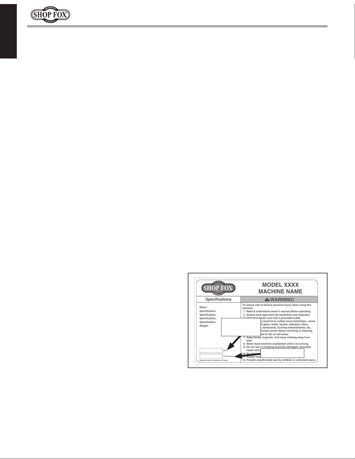
for help. Before calling, make sure you write
down the
from the machine ID label (see below). Also, if
available, have a copy of your original purchase
receipt on hand. This information is required for
all Tech Support calls.
MODEL XXXX
MACHINE NAME
Motor:
Specification:
Specification:
Specification:
Specification:
Weight:
Specifications
To reduce risk of serious personal injury when using this
machine:
1. Read & understand owner’s manual before operating.
2. Always wear approved eye protection and respirator.
3. Only plug power cord into a grounded outlet.
4. Only use this machine to collect wood dust/chips—never
use to collect glass, metal, liquids, asbestos, silica,
animal parts, biohazards, burning material/ashes, etc.
5. Always disconnect power before servicing or cleaning.
6. Do not expose to rain or wet areas.
7. Keep hands, long hair, and loose clothing away from
inlet.
8. Never leave machine unattended while it is running.
9. Do not use if cord/plug becomes damaged—promptly
repair and protect cord from future damage.
10. Do not use without dust bag or filters in place.
11. Always wear a respirator when emptying bags.
12. Prevent unauthorized use by children or untrained users.
Date
Serial Number
Manufactured for Woodstock in Taiwan
WARNING!
We are committed to customer satisfaction. If
you have any questions or need help, use the
information below to contact us.
IMPORTANT: Before contacting, please get the
original purchase receipt, serial number, and
manufacture date of your machine. This information is required for all Technical Support
calls and it will help us help you faster.
We want your feedback on this manual. What did
you like about it? Where could it be improved?
Please take a few minutes to give us feedback.
Email: manuals@woodstockint.com
Model W1839 & W1840 (For Machines Mfd. Since 3/16)
INTRODUCTION
Contact Info
Woodstock International Technical Support
Phone: (360) 734-3482
Email: techsupport@woodstockint.com
Technical Documentation Manager
P.O. Box 2309
Bellingham, WA 98227
Manual Accuracy
made every effort to be exact with
also means that sometimes the
.
,
e post current
manual updates for free
woodstockint.com.
Manufacture Date and Serial Number
Manufacture
Date
Serial Number
-2-
Page 5

Model W1839 & W1840 (For Machines Mfd. Since 3/16)
MODEL W1839
6" VARIABLESPEED GRINDER WITH WORK LIGHT
Product Dimensions
Weight........................................................................................................... 28 lbs.
Width (side‐to‐side) x Depth (front‐to‐back) x Height................................... 15 x 12 x 17‐1/2 in.
Footprint (Length x Width)..................................................................... 11‐1/4 x 6‐3/4 in.
Shipping Dimensions
Type......................................................................................................... Cardboard
Content........................................................................................................ Machine
Weight........................................................................................................... 29 lbs.
Length x Width x Height........................................................................... 21 x 13 x 11 in.
Must Ship Upright.................................................................................................. Yes
INTRODUCTION
Electrical
Power Requirement.................................................................... 120V, Single‐Phase, 60 Hz
Full‐Load Current Rating........................................................................................ 2.5A
Minimum Circuit Size............................................................................................. 15A
Power Cord Included.............................................................................................. Yes
Power Cord Length............................................................................................... 6 ft.
Power Cord Gauge............................................................................................ 18 AWG
Plug Included....................................................................................................... Yes
Included Plug Type........................................................................................ NEMA 5‐15
Switch Type............................................................. Toggle Safety Switch w/Removable Key
Motors
Main
Type........................................................................ Capacitor‐Start Induction Motor
Horsepower.............................................................................................. 1/3 HP
Phase.............................................................................................. Single‐Phase
Amps.......................................................................................................... 2.5
Speed......................................................................................... 2000 – 3400 RPM
Power Transfer ................................................................................... Direct Drive
Main Specifications
Operation Info
Grinder Type.................................................................................. Variable‐Speed
Wheel Type.................................................................................. Aluminum Oxide
Right Wheel Diameter.................................................................................... 6 in.
Left Wheel Diameter...................................................................................... 6 in.
Right Wheel Grinding Face Width.................................................................... 3/4 in.
Left Wheel Grinding Face Width..................................................................... 3/4 in.
Wheel Bore.............................................................................................. 1/2 in.
Wheel Speed at Maximum Wheel Diameter..................................................... 4450 RPM
-3-
Page 6

INTRODUCTION
Model W1839 & W1840 (For Machines Mfd. Since 3/16)
Construction
Base.................................................................................................... Cast Iron
Work Rest............................................................................................ Aluminum
Eye Shields........................................................................................ Clear Plastic
Lamp.......................................................................................................... LED
Other
Country of Origin ............................................................................................... China
Warranty ....................................................................................................... 2 Years
Approximate Assembly & Setup Time ................................................................. 15 Minutes
Serial Number Location .................................................................................... ID Label
ISO 9001 Factory .................................................................................................. Yes
Certified by a Nationally Recognized Testing Laboratory (NRTL) .......................................... No
Features
1/3 HP Variable‐Speed Induction Motor
Dual 6" Aluminum‐Oxide Grinding Wheels
1/2" Grinding Wheel Bore
4450 RPM Grinding Wheel Speed
Dual Eye Safety Shields
Dual Adjustable Aluminum Work Rests
Base Mounting Holes 3/8" (2) x 9‐7/8" OC
-4-
Page 7

Model W1839 & W1840 (For Machines Mfd. Since 3/16)
MODEL W1840
8" VARIABLESPEED GRINDER WITH WORK LIGHT
Product Dimensions
Weight........................................................................................................... 40 lbs.
Width (side‐to‐side) x Depth (front‐to‐back) x Height................................... 15‐1/2 x 12 x 19 in.
Footprint (Length x Width)..................................................................... 11‐1/4 x 6‐3/4 in.
Shipping Dimensions
Type.................................................................................................... Cardboard Box
Content........................................................................................................ Machine
Weight........................................................................................................... 43 lbs.
Length x Width x Height........................................................................... 22 x 15 x 13 in.
Must Ship Upright.................................................................................................. Yes
INTRODUCTION
Electrical
Power Requirement.................................................................... 120V, Single‐Phase, 60 Hz
Full‐Load Current Rating........................................................................................... 5A
Minimum Circuit Size............................................................................................. 15A
Power Cord Included.............................................................................................. Yes
Power Cord Length............................................................................................... 6 ft.
Power Cord Gauge............................................................................................ 18 AWG
Plug Included....................................................................................................... Yes
Included Plug Type........................................................................................ NEMA 5‐15
Switch Type............................................................. Toggle Safety Switch w/Removable Key
Motors
Main
Type........................................................................ Capacitor‐Start Induction Motor
Horsepower.............................................................................................. 3/4 HP
Phase.............................................................................................. Single‐Phase
Amps........................................................................................................... 5A
Speed......................................................................................... 2000 – 3400 RPM
Power Transfer ................................................................................... Direct Drive
Main Specifications
Operation Info
Grinder Type.................................................................................. Variable‐Speed
Wheel Type.............................................................................................. Type 1
Right Wheel Diameter.................................................................................... 8 in.
Left Wheel Diameter...................................................................................... 8 in.
Right Wheel Grinding Face Width....................................................................... 1 in.
Left Wheel Grinding Face Width........................................................................ 1 in.
Wheel Bore.............................................................................................. 5/8 in.
Wheel Speed at Maximum Wheel Diameter..................................................... 3600 RPM
-5-
Page 8

INTRODUCTION
Model W1839 & W1840 (For Machines Mfd. Since 3/16)
Construction
Base.................................................................................................... Cast Iron
Work Rest............................................................................................ Aluminum
Eye Shields........................................................................................ Clear Plastic
Lamp.......................................................................................................... LED
Other
Country of Origin ............................................................................................... China
Warranty ....................................................................................................... 2 Years
Approximate Assembly & Setup Time ................................................................. 15 Minutes
Serial Number Location .................................................................................... ID Label
ISO 9001 Factory .................................................................................................. Yes
Certified by a Nationally Recognized Testing Laboratory (NRTL) .......................................... No
Features
3/4 HP Variable‐Speed Induction Motor
Dual 8" Aluminum‐Oxide Grinding Wheels
5/8" Grinding Wheel Bore
3600 RPM Grinding Wheel Speed
Dual Eye Safety Shields
Dual Adjustable Aluminum Work Rests
Base Mounting Holes 3/8" (2) x 9‐7/8" OC
-6-
Page 9
Model W1839 & W1840 (For Machines Mfd. Since 3/16)
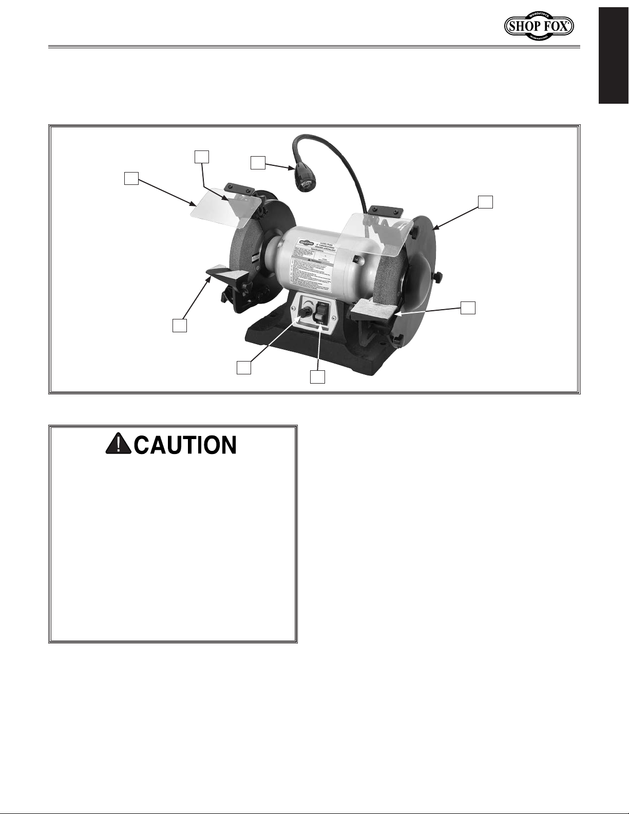
Become familiar with the names and locations of the controls and features shown below to better
Controls & Components
INTRODUCTION
B
A
H
Figure 1. W1839 & W1840 controls and components.
C
D
E
G
F
C. LED Work Lamp: Work lamp turns ON/OFF
when machine is turned ON/OFF.
For Your Own Safety Read Instruction
Manual Before Operating Grinder
a) Replace cracked wheel immediately.
b) Always use guards and eye shields.
c) Do not overtighten wheel nut.
d) Only use flanges furnished with grinder.
e) Adjust work rest to maintain
distance from wheel as diameter of
wheels will decrease with use. DO NOT
allow more than
rest and wheel.
f) Frequently clean grinding dust from
beneath grinder.
A. Safety Shield: Helps protect operator
from sparks during grinding. Shield is not
a substitute for proper personal protective
equipment.
B. Spark Deflector: Helps contain sparks
inside wheel guard to reduce operator
exposure.
1
⁄8" gap between work
1
⁄16" – 1⁄8"
D. Wheel Guard: Prevents accidental contact
with grinding wheel, and contains sparks
during grinding.
E. Tool Rest (Right): Provides flat surface to
rest workpiece during operation. Tilt angle
is adjustable.
F. ON/OFF Switch w/Disabling Key: Turns
motor ON when flipped up; turns motor
OFF when pressed down. Key prevents
motor from starting when removed.
G. Variable-Speed Dial: Controls grinding
wheel speed. Turn clockwise to increase
speed; turn counterclockwise to decrease
speed.
H. Tool Rest (Left): Provides a 60° "V" shaped
groove for sharpening drill bits. Also
includes a flat surface for general grinding.
Tilt angle is adjustable.
-7-
Page 10

Model W1839 & W1840 (For Machines Mfd. Since 3/16)
SAFETY
OWNER’S MANUAL.
TRAINED OPERATORS ONLY.
DANGEROUS ENVIRONMENTS.
MENTAL ALERTNESS REQUIRED.
electrical components or improperly grounded
manual uses a series of symbols and signal words intended to convey the level of importance of the
safety messages. The progression of symbols is described below. Remember that safety messages by
SAFETY
For Your Own Safety,
Read Manual Before Operating Machine
The purpose of safety symbols is to attract your attention to possible hazardous conditions. This
SAFETY
themselves do not eliminate danger and are not a substitute for proper accident prevention measures—this responsibility is ultimately up to the operator!
NOTICE
Standard Machinery Safety Instructions
Standard Machinery Safety Instructions
Indicates an imminently hazardous situation which, if not avoided,
WILL result in death or serious injury.
Indicates a potentially hazardous situation which, if not avoided,
COULD result in death or serious injury.
Indicates a potentially hazardous situation which, if not avoided,
MAY result in minor or moderate injury.
This symbol is used to alert the user to useful information about
proper operation of the equipment or a situation that may cause
damage to the machinery.
Read and understand this
owner’s manual BEFORE using machine.
have a higher risk of being hurt or killed. Only
allow trained/supervised people to use this
machine. When machine is not being used,
disconnect power, remove switch keys, or
lock-out machine to prevent unauthorized
use—especially around children. Make
workshop kid proof!
machinery in areas that are wet, cluttered,
or have poor lighting. Operating machinery
in these areas greatly increases the risk of
accidents and injury.
alertness is required for safe operation of
machinery. Never operate under the influence
of drugs or alcohol, when tired, or when
distracted.
Untrained operators
Do not use
Full mental
ELECTRICAL EQUIPMENT INJURY RISKS. You can
be shocked, burned, or killed by touching live
machinery. To reduce this risk, only allow an
electrician or qualified service personnel to
do electrical installation or repair work, and
always disconnect power before accessing or
exposing electrical equipment.
DISCONNECT POWER FIRST. Always disconnect
machine from power supply BEFORE making
adjustments, changing tooling, or servicing
machine. This eliminates the risk of injury
from unintended startup or contact with live
electrical components.
EYE PROTECTION. Always wear ANSI-approved
safety glasses or a face shield when operating
or observing machinery to reduce the risk of
eye injury or blindness from flying particles.
Everyday eyeglasses are not approved safety
glasses.
-8-
Page 11

Model W1839 & W1840 (For Machines Mfd. Since 3/16)
WEARING PROPER APPAREL. Do not wear
HAZARDOUS
HEARING PROTECTION.
REMOVE ADJUSTING TOOLS.
INTENDED USAGE.
AWKWARD POSITIONS.
CHILDREN & BYSTANDERS.
GUARDS & COVERS.
FORCING MACHINERY. Do not force machine. It
will do the job safer and better at the rate for
loss of control. Before starting, verify machine
malfunction, leading to serious personal injury
from heated surfaces, high traffic areas, harsh
clothing, apparel, or jewelry that can become
entangled in moving parts. Always tie back
or cover long hair. Wear non-slip footwear to
avoid accidental slips, which could cause loss
of workpiece control.
DUST. Dust created while using
machinery may cause cancer, birth defects,
or long-term respiratory damage. Be aware of
dust hazards associated with each workpiece
material, and always wear a NIOSH-approved
respirator to reduce your risk.
Always wear hearing
protection when operating or observing
loud machinery. Extended exposure to this
noise without hearing protection can cause
permanent hearing loss.
machinery can become dangerous projectiles
upon startup. Never leave chuck keys,
wrenches, or any other tools on machine.
Always verify removal before starting!
intended purpose—never make modifications
without prior approval from Woodstock
International. Modifying machine or using
it differently than intended will void the
warranty and may result in malfunction or
mechanical failure that leads to serious
personal injury or death!
balance at all times when operating machine.
Do not overreach! Avoid awkward hand
positions that make workpiece control difficult
or increase the risk of accidental injury.
bystanders at a safe distance from the work
area. Stop using machine if they become a
distraction.
Only use machine for its
Tools left on
Keep proper footing and
Keep children and
which it was designed.
NEVER STAND ON MACHINE. Serious injury may
occur if machine is tipped or if the cutting
tool is unintentionally contacted.
STABLE MACHINE. Unexpected movement during
operation greatly increases risk of injury or
is stable and mobile base (if used) is locked.
USE RECOMMENDED ACCESSORIES. Consult
this owner’s manual or the manufacturer for
recommended accessories. Using improper
accessories will increase risk of serious injury.
UNATTENDED OPERATION. To reduce the risk
of accidental injury, turn machine OFF and
ensure all moving parts completely stop
before walking away. Never leave machine
running while unattended.
MAINTAIN WITH CARE. Follow all maintenance
instructions and lubrication schedules to
keep machine in good working condition. A
machine that is improperly maintained could
or death.
CHECK DAMAGED PARTS. Regularly inspect
machine for any condition that may affect
safe operation. Immediately repair or replace
damaged or mis-adjusted parts before
operating machine.
MAINTAIN POWER CORDS. When disconnecting
cord-connected machines from power, grab
and pull the plug—NOT the cord. Pulling the
cord may damage the wires inside, resulting
in a short. Do not handle cord/plug with wet
hands. Avoid cord damage by keeping it away
chemicals, and wet/damp locations.
SAFETY
accidental contact with moving parts or flying
debris—make sure they are properly installed,
undamaged, and working correctly.
Guards and covers reduce
EXPERIENCING DIFFICULTIES. If at any time
you experience difficulties performing the
intended operation, stop using the machine!
-9-
Contact Technical Support at (360) 734-3482.
Page 12

Model W1839 & W1840 (For Machines Mfd. Since 3/16)
Additional Safety for Benchtop Grinders
Serious injury or death can occur from impact injuries if a grinding wheel breaks apart during
operation. Rotating grinding wheels can easily remove skin or cause entanglement injuries if
clothing or apparel is caught in moving parts. Fingers can be pinched/cut by in-running pinch points.
Flying sparks can ignite explosive or flammable materials. To minimize risk of injury or death,
anyone operating machine MUST completely heed hazards and warnings below.
SAFE MOUNTING & WORK AREA. An unsecured
SAFETY
grinder may become dangerously out of control
during operation. Before use, verify grinder is
FIRMLY secured in a location free of explosive
or flammable materials.
STARTING GRINDER. If a wheel is damaged, it
will usually fly apart shortly after start-up. To
protect yourself, always stand to side of grinder
when turning it ON and allow it to run for at
least one minute before standing in front of it.
VISUAL INSPECTION. Verify that grinding wheels
are free of cracks, chips, or dents in wheel
surface before installing. Do not use wheel if
it has any of these problems or it could break
apart during operation.
WHEEL SPEED RATING. Before mounting a new
wheel, be sure wheel RPM rating is equal to
or higher than speed of grinder. Never use
unmarked wheels or wheels rated for lower
RPM than grinder.
VIBRATING WHEEL. Never use a wheel that
vibrates excessively. Replace wheel or shaft
bearings immediately.
SPARK DEFLECTOR GAP. Never allow gap
between end of spark deflector and
grinding wheel to exceed
gap is larger, additional sparks and
abrasives will be expelled toward the
operator, which will increase the risk of injury.
TOOL REST POSITION. A large distance (gap)
between tool rest and wheel increases risk
of workpiece being pinched between wheel
and tool rest causing wheel breakage, loss
of control, and possible injury. Never allow
gap between tool rest and wheel to exceed
1
⁄8”. Replace grinding wheel when tool rest
gap becomes wider than
adjustment can be made to tool rest.
1
⁄4”. If the
1
⁄8″ and no additional
SIDE & TOP GRINDING. Grinding on side of
wheels can cause them to crack and burst—
unless wheel is rated for side grinding.
Grinding on top of wheels greatly increases
risk of workpiece kickback. Always grind on
downward part of wheel.
SPINDLE NUT. Only tighten wheel spindle nut
enough to drive wheel and prevent slippage.
EYE SHIELDS. Place eye shields close to grinding
wheel and re-adjust as wheel wears down.
HAND & WHEEL CONTACT. Keep a firm grip
on workpiece and position your hands a safe
distance away when grinding. Anticipate when
workpiece will heat up, and cool it before it
becomes too hot to hold, or use an appropriate
clamp. Avoid wearing gloves as they may get
caught in grinding wheel and cause even more
serious entanglement injuries.
WHEEL FLANGES. Only use flanges included with
or designed for this grinder when mounting
wheels. Other flanges may not properly
secure wheel and cause an accident. Do not
use warped or damaged flanges, and always
use paper discs (blotters) between wheels
and flanges to reduce risk of flanges cracking
wheel when tightening.
EYE, FACE, & LUNG PROTECTION. Grinding
ejects small particles at a high rate of speed.
These particles can cause blindness, skin
injuries or respiratory damage. ALWAYS wear
approved clothing, safety goggles, face shield,
and a respirator for type of grinding to be
done.
RING TEST. Perform a “ring test” on grinding
wheels before installation to ensure they are
safe to use. A wheel that does NOT pass ring
test may break or fly apart during operation.
-10-
Page 13

Model W1839 & W1840 (For Machines Mfd. Since 3/16)
This machine must be connected to the correct size and
type of power supply circuit, or fire or electrical damage
may occur. Read through this section to determine if an
adequate power supply circuit is available. If a correct
circuit is not available, a qualified electrician MUST install
one before you can connect the machine to power.
A power supply circuit includes all electrical equipment
between the breaker box or fuse panel in the building
and the machine. The power supply circuit used for
this machine must be sized to safely handle the fullload current drawn from the machine for an extended
period of time. (If this machine is connected to a circuit
protected by fuses, use a time delay fuse marked D.)
This machine is prewired to operate on a power supply
circuit that has a verified ground and meets the following
requirements:
The full-load current rating is the amperage a machine
draws at 100% of the rated output power. On machines
with multiple motors, this is the amperage drawn by the
largest motor or sum of all motors and electrical devices
that might operate at one time during normal operations.
or machine damage. To reduce this risk,
a dedicated circuit—
where only one machine will be running
multiple machines will be running at the
ELECTRICAL
Circuit Requirements
The machine must be properly set up
before it is safe to operate. DO NOT
connect this machine to the power
source until instructed to do so later in
this manual.
ELECTRICAL
Full-Load Current Rating
W1839 Full-Load Current Rating at 120V ........ 2.5 Amps
W1840 Full-Load Current Rating at 120V ...........5 Amps
Circuit Requirements for 120V
Circuit Type ............... 110V/120V, 60 Hz, Single-Phase
Circuit Size ............................................. 15 Amps
Plug/Receptacle .................................... NEMA 5-15
Incorrectly wiring or grounding this
machine can cause electrocution, fire,
only an electrician or qualified service
personnel should do any required
electrical work on this machine.
NOTICE
The circuit requirements listed in this
manual apply to
at a time. If this machine will be
connected to a shared circuit where
same time, consult with an electrician
to ensure that the circuit is properly
sized for safe operation.
-11-
Page 14

Model W1839 & W1840 (For Machines Mfd. Since 3/16)
This machine MUST be grounded. In the event of certain
types of
a path of least resistance for electric current
order
Improper connection of the equipment-grounding
will
increase
insulation
grounding
cord or plug is necessary, do not connect the equipmentgrounding
Check with a qualified electrician or service personnel
if
or if
properly grounded.
plug is damaged or worn, disconnect it from power, and
immediately replace it with a new one.
We do not recommend using an extension cord with
Any extension cord used with this machine must contain a
plug and receptacle, and
meet the following requirements:
This machine is equipped with a power cord that has an
equipment-grounding
The plug
receptacle
(
accordance with local codes and ordinances.
Grounding Requirements
malfunctions or breakdowns, grounding provides
to reduce the risk of electric shock.
the risk of electric shock. The wire with green
(with/without yellow stripes) is the equipment-
wire. If repair or replacement of the power
wire to a live (current carrying) terminal.
you do not understand these grounding requirements,
ELECTRICAL
you are in doubt about whether the tool is
If you ever notice that a cord or
For 120V Connection
wire and NE M A 5-15 grounding plug.
must only be inserted into a matching
see Figure) that is properly installed and grounded in
to travel—in
wire
120V
5-15 PLUG
Figure 2. NEMA 5-15 plug & receptacle.
DO NOT modify the provided plug or
use an adapter if the plug will not
fit the receptacle. Instead, have an
electrician install the proper receptacle
on a power supply circuit that meets
the requirements for this machine.
GROUNDED
5-15 RECEPTACLE
Grounding Prong
Neutral Hot
Extension Cords
this machine. Extension cords cause voltage drop, which
may damage electrical components and shorten motor
life. Voltage drop increases with longer extension cords
and smaller gauge sizes (higher gauge numbers indicate
smaller sizes).
ground wire, match the required
Minimum Gauge Size at 120V ...................... 16 AWG
Maximum Length (Shorter is Better) ................50 ft.
-12-
Page 15

Model W1839 & W1840 (For Machines Mfd. Since 3/16)
This machine has been carefully packaged for safe
transportation. If you notice the machine has been
damaged during shipping, please contact your authorized
Shop Fox dealer immediately.
The following items are needed, but not included, to set
up your machine.
Immediately discard all
plastic bags and packing
materials to eliminate
This machine presents
serious injury hazards
to untrained users. Read
to become familiar with
tions before starting the
SETUP
Unpacking
Items Needed for Setup
Description Qty
• Safety Glasses for Each Person ..........................1
• Degreaser or Solvent for Cleaning .......... As Needed
• Disposable Rags for Cleaning ................ As Needed
• Mounting Hardware (Page 15) ............... As Needed
• Phillips Screwdriver #2 ...................................1
• Open-End Wrench 13mm .................................1
through this entire manual
the controls and opera-
machine!
Wear safety glasses during
entire setup process!
SETUP
SUFFOCATION HAZARD!
choking/suffocation
hazards for children and
animals.
-13-
Page 16

Inventory
The following is a list of items shipped with your machine.
Before beginning setup, lay these items out and inventory
them.
Note:
check around/inside the machine and packaging materials.
Often, these items get lost in packaging materials while
unpacking or they are pre-installed at the factory.
Immediately discard all
materials to eliminate
Model W1839 & W1840 (For Machines Mfd. Since 3/16)
SUFFOCATION HAZARD!
If you cannot find an item on this list, carefully
Box Contents (Figure 3): Qty
A. Grinder (not shown) .......................................1
B. Tool Rest Bracket (Right) .................................1
C. Tool Rest Bracket (Left) ..................................1
D. Tool Rest (Left) ............................................1
E. Tool Rest (Right) ...........................................1
F. Spark Deflector (Right) ...................................1
G. Spark Deflector (Left) ....................................1
H. Safety Shield Mounting Brackets ........................2
I. Safety Shield Mounting Plates ...........................2
SETUP
J. Spark Deflectors ...........................................2
plastic bags and packing
choking/suffocation
hazards for children and
animals.
D
E
C
B
J
Figure 3. Tool rest and safety shield parts.
F
G
H
I
Hardware (Figure 4): Qty
K. Flat Washers 8mm .........................................2
L. Flat Washers 6mm .........................................4
M. Flat Washers 5mm .........................................4
N. Lock Washers 6mm ........................................4
O. Lock Washers 5mm ........................................4
P. Hex Bolts M8-1.25 x 12 ...................................4
Q. Phillips Head Screws M4-.7 x 12 ........................4
R. Carriage Bolts M6-1 x 12 .................................2
S. Phillips Head Screws M5-.8 x 10 ........................4
T. Flange Nuts M4-.7 .........................................4
U. Knobs M6-1 .................................................2
V. Knob Bolts M6-1 x 18 ......................................2
K
P
U
Figure 4. Fastener inventory.
L
Q
M N
R
O
S
V
T
-14-
Page 17

Model W1839 & W1840 (For Machines Mfd. Since 3/16)
Refer to the Machine Specifications for the
weight and footprint specifications of your
machine. Some workbenches may require
additional reinforcement to support the weight
of the machine and workpiece materials.
Machine Placement
Workbench Load
Placement Location
Consider anticipated workpiece sizes and
additional space needed for auxiliary stands,
work tables, or other machinery when
establishing a location for this machine in the
shop. Below is the minimum amount of space
needed for the machine.
Mount the grinder to a workbench to avoid
accidental tipping. For portable bench grinding,
mount it to a heavy plywood base (at least 1"
thick) that is wide enough to prevent tipping or
rocking during use.
Bench Mounting
Number of Mounting Slots ........................ 2
Diameter of Mounting Hardware Needed ..
The base of this machine has mounting holes
that allow it to be fastened to a workbench
or other mounting surface to prevent it from
moving during operation and causing accidental
injury or damage.
The strongest mounting option is a “Through
Mount” (see example) where holes are drilled all
the way through the workbench—and hex bolts,
washers, and hex nuts are used to secure the
machine in place.
Hex
Bolt
Flat Washer
3
⁄8"
SETUP
11”
12"
15"
Figure 5. W1839 minimum working clearances.
12"
11”
Machine Base
Workbench
Flat Washer
Lock Washer
Hex Nut
Figure 7. Typical "Through Mount" setup.
Another option is a “Direct Mount” (see
example) where the machine is secured directly
to the workbench with lag screws and washers.
Lag Screw
Flat Washer
Machine Base
1
2
/
15
"
Figure 6. W1840 minimum working clearances.
Workbench
Figure 8. Typical "Direct Mount" setup.
-15-
Page 18

Model W1839 & W1840 (For Machines Mfd. Since 3/16)
Before beginning the assembly process, refer to Items
Needed for Setup
Ensure all parts have been properly cleaned of the
heavy-duty rust-preventative applied at the factory, if
applicable. Be sure to complete all steps in the assembly
procedure prior to performing the Test Run.
Assembly
and gather everything you need.
To assemble machine, do these steps:
1. Assemble safety shields (see Figure 9) using (4)
M4-.7 x 12 Phillips head screws, (4) M4-.7 flange
nuts, (2) safety shield mounting plates, (2) safety
shields, and (2) safety shield mounting brackets.
2. Attach safety shield assemblies to spark deflectors
(see Figure 10) using (2) M6-1 x 12 carriage bolts,
(2) 6mm flat washers, and (2) M6-1 knobs.
SETUP
Safety
Shield
Safety Shield
Mounting Bracket
Figure 9. Safety shield components.
Safety
Shield
Assembly
Carriage
Bolt
Safety Shield
Mounting Plate
Flange
Nuts
Knob
Washer
Spark
Deflector
Phillips
Head
Screws
Flat
3. Attach each spark deflector/safety shield assembly
to grinder with (4) M5-.8 x 10 Phillips head screws,
(4) 5mm flat washers, and (4) 5mm lock washers
(see Figure 11).
4. Assemble left tool rest using (1) left tool rest
bracket, (1) left tool rest, (1) 6mm flat washer, (1)
6mm lock washer, and (1) M6-1 x 18 knob bolt (see
Figure 12).
5. Assemble right tool rest using (1) right tool rest
bracket, (1) right tool rest, (1) 6mm flat washer, (1)
6mm lock washer, and (1) M6-1 x 18 knob bolt.
Figure 10. Safety shield attached to spark
deflectors (1 or 2).
x 2
Figure 11. Spark deflector attached.
Lock
Tool Rest
Tool Rest
Bracket
Washer
Knob
Bolt
Flat
Washer
Figure 12. Tool rest assembly.
-16-
Page 19

Model W1839 & W1840 (For Machines Mfd. Since 3/16)
6. Attach each tool rest assembly to grinder using (4)
M8-1.25 x 12 hex bolts and (4) 8mm flat washers
(see Figure 13).
Some grinding wheels must be replaced before spark
deflector or tool rest reach their final adjustment. As
diameter of a grinding wheel is reduced, so is surface
speed. Grinding under these conditions can lead to
faster abrasive loss and poor grinding results. Always
follow wheel manufacturer's directions.
Tool Rest Adjustment
The toll rest can be adjusted closer/farther from grinding
wheel or tilted and secured every 15° from 0°—75°.
The tool rest stabilizes the workpiece when grinding.
It must always be positioned correctly when using the
grinder to help prevent the operator's hands from being
pulled into grinding wheel.
x 4
x 4
Figure 13. Tool rest assembly attached to
grinder.
1
⁄16" –1⁄8"
SETUP
Each tool rest features detents that allow it to lock at a
specific angle. To adjust a tool rest, loosen the knob bolt
(see Figure 13) several turns, pivot the tool rest to the
1
appropriate angle, position it
⁄16" away from the grinding
wheel, and then tighten knob bolt to secure setting.
As grinding wheel wears, shift tool rest closer to grinding
1
wheel to maintain a gap of
IMPORTANT: If the gap reaches
⁄16" –1⁄8" (see Figure 14).
1
⁄8" and the tool rest
cannot be adjusted any closer to the wheel, the grinding
wheel MUST be replaced before you can resume safely
operating grinder.
Spark Deflector Adjustment
The spark deflector prevents sparks from showering the top
of the workpiece and the operator's hands. As the wheel
wears, adjust the spark deflector closer to the grinding
wheel to maintain a gap of
1
the gap reaches
⁄4" and no additional adjustments can be
made, replace the grinding wheel.
1
⁄8"–1⁄4" (see Figure 15). If
Knob
Bolt
Figure 14. Tool rest gap.
1
⁄8" –1⁄4"
Never grind WITHOUT tool rest in place and properly
positioned. "Free hand" grinding or too large of a gap
between wheel and tool rest increases risk of pinching,
which may result in wheel breakage or operator injury.
-17-
Figure 15. Spark deflector gap.
Page 20

Test Run
performed. Operating an improperly set
Once assembly is complete, test run the machine to
ensure it is properly connected to power and safety
components are functioning properly.
If you find an unusual problem during the test run,
immediately stop the machine, disconnect it from power,
and fix the problem BEFORE operating the machine again.
The
section of this
manual can help.
Troubleshooting table in the SERVICE
To test run machine, do these steps:
Model W1839 & W1840 (For Machines Mfd. Since 3/16)
Serious injury or death can result
from using this machine BEFORE
understanding its controls and related
safety information. DO NOT operate, or
allow others to operate, machine until
the information is understood.
1. Clear all setup tools away from machine.
2. Connect machine to power supply.
3. Rotate variable-speed dial all the way left and turn
machine ON, verify motor operation, and slowly
rotate variable-speed dial to the right, then turn
machine OFF.
SETUP
The motor should run smoothly and without unusual
noises.
4. Remove key from toggle switch (see Figure 16).
5. Try to start machine with switch.
Machine should NOT start. If it does start, the switch
disabling feature is not functioning properly and the
switch must be replaced.
DO NOT start machine until all
preceding setup instructions have been
up machine may result in malfunction
or unexpected results that can lead
to serious injury, death, or machine/
property damage.
Figure 16. Removing switch key from
toggle switch.
-18-
Page 21

Model W1839 & W1840 (For Machines Mfd. Since 3/16)
If you are an inexperienced operator, we
or trade articles, or seek training from
machinery before performing unfamiliar
This machine will perform many types of operations
that are beyond the scope of this manual. Many of these
operations can be dangerous or deadly if performed
incorrectly.
The instructions in this section are written with the
understanding that the operator has the necessary
knowledge and skills to operate this machine. If at any
time you are experiencing difficulties performing any
operation, stop using the machine!
The overview below provides the novice machine operator
with a basic understanding of how the machine is used
during operation, so the machine controls/components
discussed later in this manual are easier to understand.
Due to its generic nature, this overview is
to be an instructional guide.
OPERATIONS
Operation Overview
To reduce your risk of serious injury
or damage to the machine, read this
entire manual BEFORE using machine.
NOT intended
To complete a typical operation, the operator does the
following:
1. Ensures workpiece is suitable for grinding.
2. Selects correct grinding wheel for operation,
inspects wheel, performs a "ring test," and installs
wheel.
3. Verifies/adjusts tool rest position so gap is
perpendicular and
and verifies/adjusts spark deflector and wheel gap is
between
4. Positions safety shield for safe grinding.
5. Ensures that ON/OFF switch is in OFF position and
variable-speed dial is turned all the way left, then
connects grinder to power.
6. Puts on personal protective equipment.
1
⁄8"—1⁄4".
1
⁄16"—1⁄8" from grinding wheel,
To reduce the risk of eye injury and
long-term respiratory damage, always
wear safety glasses and a respirator
while operating this machine.
strongly recommend that you read books
an experienced operator of this type of
operations. Above all, safety must come
first!
9. Operator gradually feeds workpiece
into grinding wheel and moves
workpiece left and right to prevent
grooves in wheel.
OPERATIONS
7. Stands aside, starts grinder, and allows it to reach
full speed and operate for at least one minute to
ensure grinding wheel does not fly apart from the
centrifugal force of rotation.
8. Positions workpiece on tool rest for grinding.
10. Quenches workpiece as required to
prevent surface hardening or temper
loss.
11. Stops bench grinder.
-19-
Page 22

Model W1839 & W1840 (For Machines Mfd. Since 3/16)
Workpiece Inspection Wheel Selection
Some workpieces are not suitable for grinding
on a bench grinder. Before grinding, inspect all
workpieces for the following:
• Hard Workpiece: Workpieces that are made
of stone, carbide, stainless steel, ceramics,
glass, or have hardened welds will wear out
most general-grade grinding wheels quickly.
If hard materials are to be ground, you must
install the correct type of grinding wheel.
• Soft Workpiece: Workpieces that are made
of aluminum, brass, lead, and other nonferrous metals will load up in the grinding
wheel and render the abrasive useless.
Grinding wood, plastics, rubber, fiberglass,
or other soft materials can also cause the
same problem and lead to the wheel overheating and possibly bursting during use if
ignored. To restore a loaded grinding wheel
surface, redress with a dressing tool.
• Flexible/Unstable Workpiece: Grinding on
the side or the ends of cable, chain, or round
workpieces creates the hazard of workpiece
twist or grab, leading to entanglement with
the wheel or shaft. This hazard must be
avoided.
• Loose Parts: Make sure that the workpiece
OPERATIONS
is free of any parts like springs, pins, balls,
or other components that may loosen or dislodge during grinding, and hit the operator.
• Strength: Make sure that the workpiece is
strong enough to be ground. Should it break,
the broken piece may dig into the wheel and
cause kickback or severe injury.
Electrical system is not waterproof. DO NOT
use grinder with liquid cooling system for
wet grinding. Ignoring warning can lead to
electrocution or machine damage.
The Model W1839 only accepts Type-1 wheels
with a
wheels with a
Aluminum oxide and silicon carbide wheels are
marked in a somewhat uniform manner by all
the major manufacturers. Understanding these
markings will help you understand the capabilities of various wheels. Always refer to the
manufacturer’s grinding recommendations when
selecting a wheel for your project.
The basic format for wheel numbering is:
The Prefix is the manufacturer’s designation for
a particular wheel type (e.g. Type-1 wheels).
The most common Abrasive Types used are A
for Aluminum Oxide, C for Silicon Carbide, and
occasionally SG for Seeded Gel.
The Grit Size is a number that refers to the
size of the abrasive grain in the wheel. The
lower the number, the coarser the wheel. Ten
is a very coarse wheel for roughing, and 220 is
usually the upper range for fine finish work.
Grade is an indication of the hardness of the
wheel—“A” being the softest and “Z” being the
hardest.
Bond Type refers to the type of bonding
material used to hold the abrasive material.
Most general purpose wheels will have a “V”
indicating Vitrified Clay is used. Vitrified Clay
provides high strength and good porosity. The
other common bond type is “B” for resin where
synthetic resins are used. These are used to
grind cemented carbide and ceramic materials.
Note: There may be other numbers inserted
that have meaning for a particular type of
wheel. Refer to the manufacturer’s technical
data for a complete explanation.
1
⁄2" bore. The W1840 only accepts Type-1
Prefix
1 A 60 L V
5
⁄8" bore.
Abrasive
Type
Grit Size Grade
Bond
Type
-20-
Page 23

Model W1839 & W1840 (For Machines Mfd. Since 3/16)
Wheel Inspection
Before mounting a new grinding wheel, it must be
inspected. Do not assume that a wheel is in sound
condition just because it is new—often, damage can occur
in shipping, with age, or with exposure to moisture.
First, do a Visual Inspection. Look for any cracks, chips,
nicks, or dents in the surface of the wheel. If you see any
of these, DO NOT use the wheel.
Second, do a Rin g Test. This test will give you an
indication of any internal damage that may not be obvious
during a visual inspection.
To perform ring test, do these steps:
STOP
Rated 3500 RPM
Make sure your grinder is not
faster than the rated RPM of this wheel
Type-1
Aluminum
Oxide
WARNING
Grinding can be dangerous
Visually inspect this wheel
for cracks, nicks,chips
60 Grit
Grade L
Vitrified Bond
1. Make sure grinding wheel is clean and dry;
otherwise, you may get false results.
2. Hang wheel in air with a piece of cord or string
looped through mounting hole in center.
3. At spots shown in Figure 17, gently tap grinding
wheel with a light non-metallic device such as
handle of a screwdriver or a wooden mallet.
Note: Finding exact spot to tap may take several
attempts.
4. An undamaged grinding wheel will emit a clear
metallic ring or “ping” sound in each of these spots.
A damaged grinding wheel will respond with a dull
thud that has no clear tone.
— If you determine from the ring test that a grinding
wheel is damaged, DO NOT use it!
Figure 17. Tapping locations when
performing a ring test.
Warped wheel flanges can increase
risk of grinding wheel breaking and
flying apart. Never use warped wheel
flanges. Always check flanges for flatness before installing grinding wheel.
OPERATIONS
-21-
Page 24

Model W1839 & W1840 (For Machines Mfd. Since 3/16)
Wheel Care
When grinding, your safety depends, to a large degree,
on the condition of the wheel. A wheel in poor condition
could break apart during rotation and injure the operator
and others in the area.
Here are some tips to help you avoid breaking the
wheel:
• Always transport, store and handle wheels with care.
Wheels may be damaged if they are dropped or if
heavy objects are stacked on them.
• Select the right grinding wheel for the job. DO NOT
grind material inappropriate for the wheel type.
• Only use wheels that are rated for the RPM of the
grinder.
• Mount the wheel properly (see Wheel Removal &
Installation on Page 24).
• Do not push the workpiece into the grinding wheel
with such force that it causes the grinder to bog
down. And do not apply pressure to stop the wheel
after turning the grinder OFF.
• Dress the wheel when necessary. Do not allow it to
become glazed (see Wheel Dressing on Page 23).
• Do not store wheels in damp or wet locations.
OPERATIONS
• Do not overtighten the nut when mounting the
wheel.
-22-
Page 25

Model W1839 & W1840 (For Machines Mfd. Since 3/16)
Wheel Dressing
Depending on the type of grinding you do, the grinding
wheel may require periodic dressing.
There are several different types of wheel dressing
devices available on the market (see Accessories on
Page 25 for examples). Dressing restores the abrasive
quality of the wheel surface and brings the wheel edge
back to square.
Refer to the instructions that accompany your dressing
accessory for complete details on how to properly dress
the wheel.
To dress grinder wheel, do these steps:
1. Turn grinder ON.
2. Place wheel dresser on tool rest with dressing wheels
facing toward grinding wheel.
3. Slowly move dressing wheel toward grinding wheel
and maintain slight pressure until a clear, even grinding surface appears across face of wheel.
4. Turn grinder OFF.
Always adjust the tool rest and spark
deflector after dressing or replacing
the grinding wheel. Failure to do so
could lead to workpiece kickback and
injury.
Grinder
Wheel
Wheel
Dresser
Tool
Rest
Figure 21. Example of dressing grinder
wheel.
OPERATIONS
5. Adjust spark deflector and tool rest as shown on
Page 17.
-23-
Page 26

Wheel Removal &
Installation
Model W1839 & W1840 (For Machines Mfd. Since 3/16)
To remove and install grinding wheel, do these steps:
1. DISCONNECT MACHINE FROM POWER!
2. Remove outer guard by removing (3) knob bolts, (3)
6mm lock washers, and (3) 6mm flat washers that
secure outer guard (see Figure 18).
3. Remove M16-2 hex nut (see Figure 19).
Tip: Hold grinding wheel with free hand to stop it
from turning while loosening the hex nut.
Note: Nut on left side of grinder has left-hand
threads. Turn it clockwise to loosen.
4. Remove outer grinding wheel flange and paper disc.
5. Remove grinding wheel from spindle. Take note
of paper or fiber disc between wheel flanges and
wheel. These cushion the pressure of the wheel
flanges and help distribute pressure more evenly.
They also help reduce damage to the flanges.
Outer
Guard
Figure 18. Location of outer guard
hardware that must be removed when
removing wheel.
Outer Grinding
Wheel Flange
Paper
Disc
M16-2 Hex Nut
6. Verify flatness of inner and outer flanges by placing
them on a flat surface. If either flange is warped or
damaged, replace it.
OPERATIONS
7. Mount new grinding wheel, as shown in Figure 20.
Tighten M16-2 hex nut snugly but do not overtighten. Over-tightening can stress and crack wheel.
8. Re-assemble outer wheel guard using hardware
removed in Step 2.
9. While standing away from line of rotation, turn
grinder ON and run new grinding wheel for at least
1–2 minutes before standing in front of it. This helps
protect you if the wheel has internal damage that
will cause it to fly apart from the centrifugal force
of rotation.
— If grinder runs smoothly, grinding wheel may now
be used.
— If wheel appears to wobble, grinder vibrates
excessively, or any other unsafe condition appears
with new wheel, stop grinder and refer to
Troubleshooting on Page 27.
Figure 19. Outer wheel guard removed.
NEVER assemble grinding wheel on
spindle without paper or fiber discs
between wheel and flange. Not using
discs can put stress on wheel, causing
it to crack and possibly fly apart.
Paper Discs
u
m
n
i
n
m
O
u
l
x
A
i
d
e
M
P
T
y
R
p
0
e
0
-
1
5
3
V
i
t
r
i
f
i
e
d
B
o
n
d
Figure 20. Assembly order for wheel
installation.
-24-
Page 27

Model W1839 & W1840 (For Machines Mfd. Since 3/16)
ACCESSORIES
Grinder Accessories
The following grinder accessories may be available through your local Woodstock International Inc.
Dealer. If you do not have a dealer in your area, these products are also available through online
dealers. Please call or e-mail Woodstock International Inc. Customer Service to get a current listing of
dealers at: 1-800-840-8420 or at sales@woodstockint.com.
The D 4144 Shop Fox Drill Sharpener mounts next to your bench
grinder and can sharpen drill bits from
accuracy. Adjustable for various drill-point angles.
The D4141 Drill Gauge Set offers 3 steel plates with clear markings,
precision stamped gauge holes and lists numbered (1 – 60), lettered
(A - Z) and fractional (
ing and check those drill sizes before you drill that hole! It even
includes a tap drill/clearance drill reference chart.
The D3744 STEELEX Diamond Dresser with Handle features a 0.25
carat diamond tip for trueing abrasive grinding wheels fast and easy
while exposing a fresh surface for efficient grinding operations.
Simply guide the Diamond Dresser against the grinder's tool rest to
restore the wheel back to its original condition. Overall length is
1
⁄2" long with a 33⁄4" long handle. The industrial diamond measures
8
0.25 carat.
1
⁄16" – 1⁄2" by 1⁄64") sized drill bits. Stop guess-
1
⁄8" to 3⁄4" with speed and
OPERATIONS
-25-
Page 28

Model W1839 & W1840 (For Machines Mfd. Since 3/16)
MAINTENANCE
Schedule
For optimum performance from your machine, follow
this maintenance schedule and refer to any specific
instructions given in this section.
Daily Check
• Loose mounting bolts.
• Cracked or loose grinding wheel.
• Worn or damaged wires.
• Any other unsafe condition.
Grinding Wheels
The grinding wheels should be inspected before every
use. Use the ring test method noted in Wheel Inspection
on Page 21 to verify the structural integrity. Take care in
storing grinding wheels to keep them free from potential
damage by being dropped or having other items drop on
them. Replace the wheel when the spark deflector or tool
rest has no more adjustment and the gap has exceeded
the safe limit.
MAKE SURE that your machine is
unplugged during all maintenance procedures! If this warning is ignored, serious personal injury may occur.
Cleaning & Protecting
Cleaning the grinder is relatively easy. Vacuum excess
debris, and wipe off the remaining dust with a dry cloth.
Wheel Storage
Grinding wheels can be easily damaged, so it is important
to store them properly. Follow all wheel manufacturer
storage instructions. Always store grinding wheels in a
location that is dry and protected from potential damage
MAINTENANCE
due to them being dropped or having other items dropped
on them. Also, avoid storing grinding wheels where there
is high humidity, extreme heat or cold, or solvents.
Wheel Dressing
Depending on the type of grinding you do, the grinding
wheel may require periodic dressing. Dressing restores the
abrasive quality of the wheel surface and squares up the
wheel edge. Refer to the instructions that accompany your
dressing accessory for complete details on how to properly
dress a wheel.
-26-
Page 29

Model W1839 & W1840 (For Machines Mfd. Since 3/16)
The following troubleshooting tables cover common problems that may occur with this machine. If you
need replacement parts or additional troubleshooting help, contact our Technical Support.
Note:
available, your original purchase receipt. This information is required to properly assist you.
SERVICE
Troubleshooting
Before contacting Tech Support, find the machine serial number and manufacture date, and if
Motor and Electrical
PROBLEM POSSIBLE CAUSE CORRECTIVE ACTION
Machine does not
start or a breaker
trips.
Machine stalls or
is underpowered.
Machine has
vibration or
noisy operation.
1. Switch disabling key removed.
2. Incorrect power supply voltage or circuit size.
3. Power supply circuit breaker tripped or fuse
blown.
4. Motor wires connected incorrectly.
5. Potentiometer/variable-speed dial controller
at fault.
6. Circuit board at fault.
7. Motor at fault.
1. Machine undersized for task.
2. Motor wired incorrectly.
3. Motor overheated.
4. Run capacitor at fault.
5. Motor bearings at fault
1. Machine incorrectly mounted to workbench or
floor.
2. Motor or component loose.
3. Grinding wheel at fault/arbor hole not round.
4. Motor bearings at fault.
5. Motor shaft bent.
.
1. Install switch disabling key.
2. Ensure correct power supply voltage and circuit
size.
3. Ensure circuit is sized correctly and free of shorts.
Reset circuit breaker or replace fuse.
4. Correct motor wiring connections.
5. Test/replace.
6. Inspect/replace.
7. Test/repair/replace.
1. Use new grinding wheel; reduce feed rate/pressure.
2. Wire motor correctly.
3. Clean motor, let cool, and reduce workload.
4. Test/repair/replace.
5. Test by rotating shaft; rotational grinding/loose
shaft requires bearing replacement.
1. Adjust feet, shim, or tighten mounting hardware.
2. Inspect/replace damaged bolts/nuts, and re-tighten with thread-locking fluid.
3. Dress/replace grinding wheel (Page 23).
4. Test by rotating shaft; rotational grinding/loose
shaft requires bearing replacement.
5. Test with dial indicator and replace motor.
-27-
SERVICE
Page 30

Model W1839 & W1840 (For Machines Mfd. Since 3/16)
Operation
PROBLEM POSSIBLE CAUSE CORRECTIVE ACTION
Machine slows
when operating.
Wavy condition
on surface of
workpiece.
Lines on surface
of workpiece.
Burning spots
or cracks in the
workpiece.
Wheel dulls
quickly, grit
falls off.
1. Operator applying too much pressure too
quickly.
2. RPM too low.
1. Machine vibrating.
2. Workpiece not being held firmly.
3. Wheel face uneven.
4. Wheel is too hard.
1. Impurity on wheel surface.
2. Workpiece not being held tightly.
1. Improper type of grinding wheel.
2. Improper feed rate.
3. Workpiece requires quenching.
1. Operator applying too much pressure too
quickly.
2. Wheel is too soft.
3. Wheel diameter too small.
4. Bad wheel dress.
5. Defective wheel bonding.
1. Slow down rate of movement of workpiece into
wheel; use less pressure.
2. Adjust RPM.
1. Ensure machine is securely mounted to a solid surface (Page 15).
2. Use a holding device to firmly retain workpiece.
3. Dress grinding wheel (Page 23).
4. Use softer wheel or reduce feed rate.
1. Dress grinding wheel (Page 23).
2. Use a holding device to firmly retain workpiece.
1. Try a wheel with softer style or a coarser grit.
2. Slow down rate of movement of workpiece into
wheel.
3. Quench workpiece in water to cool.
1. Slow down rate of movement of workpiece into
wheel; use less pressure.
2. Wheel too soft for material being ground, select
harder bond.
3. Replace grinding wheel (Page 24).
4. Re-dress grinding wheel (Page 23).
5. Replace grinding wheel. Consult manufacturer of
grinding wheel.
SERVICE
-28-
Page 31

Model W1839 & W1840 (For Machines Mfd. Since 3/16)
These pages are current at the time of printing. However, in the spirit of improvement, we may make
changes to the electrical systems of future machines. Compare the manufacture date of your machine to
If there are differences between your machine and what is shown in this section, call Technical Support
for assistance BEFORE making any changes to the wiring on your machine. An updated
machine before calling. This information can be found on the main machine label.
Electrical Safety Instructions
the one stated in this manual, and study this section carefully.
at (360) 734-3482
wiring diagram may be available. Note: Please gather the serial number and manufacture date of your
SHOCK HAZARD. Working on wiring that is
connected to a power source is extremely
dangerous. Touching electrified parts will
result in personal injury including but not
limited to severe burns, electrocution,
or death. Disconnect the power from
the machine before servicing electrical
components!
QUALIFIED ELECTRICIAN. Due to the inherent
hazards of electricity, only a qualified
electrician should perform wiring tasks on
this machine. If you are not a qualified
electrician, get help from one before
attempting any kind of wiring job.
WIRE CONNECTIONS. All connections must
be tight to prevent wires from loosening
during machine operation. Double-check all
wires disconnected or connected during any
wiring task to ensure tight connections.
WIRE/COMPONENT DAMAGE. Damaged wires
or components increase the risk of serious
personal injury, fire, or machine damage. If
you notice that any wires or components are
damaged while performing a wiring task,
replace those wires or components before
completing the task.
MODIFICATIONS. Using aftermarket parts or
modifying the wiring beyond what is shown
in the diagram may lead to unpredictable
results, including serious injury or fire.
MOTOR WIRING. The motor wiring shown
in these diagrams is current at the time
of printing, but it may not match your
machine. Always use the wiring diagram
inside the motor junction box.
CAPACITORS/INVERTERS. Some capacitors
and power inverters store an electrical
charge for up to 10 minutes after being
disconnected from the power source.
To reduce the risk of being shocked,
wait at least this long before working on
capacitors.
CIRCUIT REQUIREMENTS. You MUST follow
the requirements at the beginning of this
manual when connecting your machine to a
power source.
EXPERIENCING DIFFICULTIES. If you are
experiencing difficulties understanding
the information included in this section,
contact our Technical Support at
(360) 734-3482.
SERVICE
WIRING DIAGRAM COLOR KEY
The photos and diagrams
included in this section are
best viewed in color. You
can view these pages in
color at www.shopfox.biz.
BLACK
WHITE
GREEN
RED
BLUE
BROWN
GRAY
ORANGE
-29-
YELLOW
YELLOW
GREEN
PURPLE
PINK
LIGHT
BLUE
BLUE
WHITE
TURQUOISE
Page 32

120 Volt Motor
Model W1839 & W1840 (For Machines Mfd. Since 3/16)
Wiring Diagram
Wt
Wt
Run
Capacitor
45MFD
250VAC
Ground
Ground
Rotation
Sensor
Wt
Wt
Wt
Speed Control
Potentiometer
B103
Wt
B103
Switch Panel
(Viewed from Back)
Safety Switch
KEDU HY7
Wt
Read
Page 29
STOP
Before
Wiring
R27
E123995
Wt
U6
Wt
T2/M
T1/M
T10AL/250V
F1
T4/L
T2/N
Grinder Base
(Viewed from Bottom)
SERVICE
Circuit Board Box
(Viewed from Top)
Hot
Neutral
Ground
Wt
Wt
120 VAC
The motor wiring shown here is
current at the time of printing, but it
may not match your machine.
Always use the wiring diagram
inside the motor junction box.
-30-
5-15 Plug
(Pre-Wired)
Page 33

Model W1839 & W1840 (For Machines Mfd. Since 3/16)
PARTS
W1839 Main Breakdown
2236
13
74
77
76
29
44
30
75
45
46
26
43
24
71
40
47
38
39
42
37
41
53
73
20
18
67
31
29
18
70
68
33
34
69
15
71
47
72
22
15
23
16
77
76
24
47
17
71
29
18
19
44
30
27
18
12
20
52
21
51
50
46
49
11
25
78
79
48
10
28
55
2
63
80
56
58
6
57
64
61
63
59
14
60
62
42
54
5
9
8
81
7
5
4
3
1
65
66
71
47
31
29
32
33
34
35
PARTS
-31-
Page 34

Model W1839 & W1840 (For Machines Mfd. Since 3/16)
W1839 Parts List
REF PART # DESCRIPTION REF PART # DESCRIPTION
1 X1839001 LAMP CIRCUIT BOARD 42 X1839042 GROMMET
2 X1839002 CIRCUIT BOARD E123995 43 X1839043 HEX NUT M4-.7
3 X1839003 TAP SCREW M3 X 5 44 X1839044 LOCK WASHER 6MM
4 X1839004 CIRCUIT BOARD COVER 45 X1839045 INNER MOTOR COVER
5 X1839005 PHLP HD SCR M4-.7 X 8 W/CAPTIVE WASHER 46 X1839046 BALL BEARING 6202ZZ
6 X1839006 R CAPACITOR 30M 300V 1-3/8 X 3 47 X1839047 FLAT WASHER 5MM
7 X1839007 BASE 48 X1839048 ROTOR
8 X1839008 STRAIN RELIEF MOUNTING PLATE 49 X1839049 STATOR
9 X1839009 PHLP HD SCR M5-.8 X 10 50 X1839050 WAVY WASHER 12MM
10 X1839010 STRAIN RELIEF TYPE-1 10MM 51 X1839051 MOTOR COVER (L)
11 X1839011 POWER CORD 14G 3W 72" 5-15P 52 X1839052 PHLP HD SCR M4-.7 X 145 W/CAPTIVE WASHER
12 X1839012 FLAT WASHER 12MM 53 X1839053 FLANGE NUT M4-.7
13 X1839013 LED LIGHT 54 X1839054 EXT TOOTH WASHER 4MM
14 X1839014 PHLP HD SCR M5-.8 X 8 55 X1839055 PHLP HD SCR M4-.7 X 16
15 X1839015 KNOB BOLT M5-.8 X 10 3-LOBE 56 X1839056 WIRE CLIP PLASTIC
16 X1839016 OUTER WHEEL COVER (L) 57 X1839057 PHLP HD SCR M6-1 X 18 W/CAPTIVE WASHER
17 X1839017 HEX NUT M12-1.75 LH 58 X1839058 POTENTIOMETER B103
18 X1839018 WHEEL FLANGE 59 X1839059 SWITCH MOUNTING PLATE
19 X1839019 GRINDING WHEEL 6 X 1/2 X 3/4 AO60 60 X1839060 TOGGLE SWITCH KEDU HY7
20 X1839020 PHLP HD SCR M5-.8 X 10 W/CAPTIVE WASHER 61 X1839061 SPEED KNOB SPACER
21 X1839021 INNER WHEEL COVER (L) 62 X1839062 SPEED ADJ KNOB
22 X1839022 CARRIAGE BOLT M6-1 X 12 63 X1839063 PHLP HD SCR M5-.8 X 16 W/CAPTIVE WASHER
23 X1839023 SPARK DEFLECTOR (L) 64 X1839064 PHLP HD SCR M4-.7 X 8 W/CAPTIVE WASHER
24 X1839024 PHLP HD SCR M5-.8 X 10 W/CAPTIVE WASHER 65 X1839065 BASE PLATE
25 X1839025 HEX NUT M4-.7 66 X1839066 RUBBER FOOT
26 X1839026 EYESHIELD (R) 67 X1839067 GRINDING WHEEL 6 X 1/2 X 3/4 AO36
27 X1839027 EYESHIELD (L) 68 X1839068 HEX NUT M12-1.75
28 X1839028 PHLP HD SCR M4-.7 X 8 69 X1839069 OUTER WHEEL COVER (R)
29 X1839029 FLAT WASHER 6MM 70 X1839070 TOOL REST (RIGHT)
30 X1839030 KNOB M6-1 71 X1839071 LOCK WASHER 5MM
31 X1839031 KNOB BOLT M6-1 X 14 3-LOBE 72 X1839072 SUPPORT BRACKET (R)
32 X1839032 TOOL REST (L) 73 X1839073 INNER WHEEL COVER (R)
33 X1839033 HEX BOLT M8-1.25 X 12 74 X1839074 LED LENS
34 X1839034 FLAT WASHER 8MM 75 X1839075 LED COVER
35 X1839035 SUPPORT BRACKET (L) 76 X1839076 FLANGE NUT M4-.7
36 X1839036 SPARK DEFLECTOR (R) 77 X1839077 PHLP HD SCR M4-.7 X 10
37 X1839037 MOTOR COVER (R) 78 X1839078 L-BRACKET METAL
38 X1839038 SET SCREW M5-.8 X 6 79 X1839079 HEX NUT M8-1.25
39 X1839039 FEEDBACK WHEEL 80 X1839080 MACHINE ID LABEL
40 X1839040 PHLP HD SCR M2.5-.45 X 6 81 X1839081 TOUCH-UP PAINT, SHOP FOX WHITE
41 X1839041 RPM SENSOR
PARTS
-32-
Page 35

Model W1839 & W1840 (For Machines Mfd. Since 3/16)
W1840 Main Breakdown
36
24
22
47
71
38
39
40
42
48
42
54
10
9
8
81
7
78
79
4
31
22
15
16
23
24
77
76
47
71
17
29
71
18
47
44
19
30
27
13
18
74
12
30
20
52
35
75
44
21
34
47
29
51
33
77
76
47
45
46
50
26
43
49
46
11
29
32
37
5
25
15
69
68
18
67
18
73
53
41
5
3
1
28
55
65
6
66
20
44
57
2
80
56
31
47
58
29
61
33
70
59
14
62
63
64
71
47
72
34
60
-33-
PARTS
Page 36

Model W1839 & W1840 (For Machines Mfd. Since 3/16)
W1840 Parts List
REF PART # DESCRIPTION REF PART # DESCRIPTION
1 X1840001 LAMP CIRCUIT BOARD 42 X1840042 GROMMET
2 X1840002 CIRCUIT BOARD E123995 43 X1840043 FLANGE NUT M5-.8
3 X1840003 TAP SCREW M3 X 5 44 X1840044 LOCK WASHER 6MM
4 X1840004 CIRCUIT BOARD COVER 45 X1840045 INNER MOTOR COVER (R)
5 X1840005 PHLP HD SCR M4-.7 X 8 46 X1840046 BALL BEARING 6203ZZ
6 X1840006 R CAPACITOR 45M 250V 1-3/8 X 3 47 X1840047 FLAT WASHER 5MM
7 X1840007 BASE 48 X1840048 ROTOR
8 X1840008 STRAIN RELIEF MOUNTING PLATE 49 X1840049 STATOR
9 X1840009 PHLP HD SCR M5-.8 X 10 50 X1840050 WAVY WASHER 12MM
10 X1840010 STRAIN RELIEF TYPE-1 10MM 51 X1840051 MOTOR COVER (L)
11 X1840011 POWER CORD 14G 3W 72" 5-15P 52 X1840052 PHLP HD SCR M5-.8 X 160
12 X1840012 FLAT WASHER 12MM 53 X1840053 HEX NUT M5-.8
13 X1840013 LED LIGHT 54 X1840054 EXT TOOTH WASHER 4MM
14 X1840014 PHLP HD SCR M5-.8 X 8 55 X1840055 PHLP HD SCR M4-.7 X 16
15 X1840015 KNOB M5-.8 X 10 3-LOBE 56 X1840056 WIRE CLIP PLASTIC
16 X1840016 OUTER WHEEL COVER (L) 57 X1840057 HEX BOLT M6-1 X 18
17 X1840017 HEX NUT M12-1.75 58 X1840058 POTENTIOMETER B103
18 X1840018 WHEEL FLANGE 59 X1840059 SWITCH MOUNTING PLATE
19 X1840019 GRINDING WHEEL 8 X 1/2 X 3/4 AO60 60 X1840060 TOGGLE SWITCH KEDU HY7
20 X1840020 PHLP HD SCR M5-.8 X 10 61 X1840061 SPEED KNOB SPACER
21 X1840021 INNER WHEEL COVER (L) 62 X1840062 SPEED ADJ KNOB
22 X1840022 HEX BOLT M6-1 X 12 63 X1840063 PHLP HD SCR M5-.8 X 16
23 X1840023 SPARK DEFLECTOR (L) 64 X1840064 PHLP HD SCR M4-.7 X 8
24 X1840024 HEX BOLT M5-.8 X 10 65 X1840065 BASE PLATE
25 X1840025 HEX NUT M4-.7 66 X1840066 RUBBER FOOT
26 X1840026 EYESHIELD (R) 67 X1840067 GRINDING WHEEL 8 X 1/2 X 3/4 AO36
27 X1840027 EYESHIELD (L) 68 X1840068 HEX NUT M12-1.75
28 X1840028 PHLP HD SCR M4-.7 X 8 69 X1840069 OUTER WHEEL COVER (R)
29 X1840029 FLAT WASHER 6MM 70 X1840070 TOOL REST (R)
30 X1840030 KNOB M6-1 71 X1840071 LOCK WASHER 5MM
31 X1840031 KNOB BOLT M6-1 X 14 3-LOBE 72 X1840072 SUPPORT BRACKET (R)
32 X1840032 TOOL REST (L) 73 X1840073 INNER WHEEL COVER (R)
33 X1840033 HEX BOLT M8-1.25 X 12 74 X1840074 LED LENS
34 X1840034 FLAT WASHER 8MM 75 X1840075 LED COVER
35 X1840035 SUPPORT BRACKET (L) 76 X1840076 FLANGE NUT M4-.7
36 X1840036 SPARK GUARD (R) 77 X1840077 PHLP HD SCR M4-.7 X 10
37 X1840037 MOTOR COVER (R) 78 X1840078 L-BRACKET METAL
38 X1840038 SET SCREW M5-.8 X 6 79 X1840079 HEX NUT M8-1.25
39 X1840039 FEEDBACK WHEEL 80 X1840080 MACHINE ID LABEL
40 X1840040 PHLP HD SCR M2.5-.45 X 6 81 X1840081 TOUCH-UP PAINT, SHOP FOX WHITE
41 X1840041 RPM SENSOR
PARTS
-34-
Page 37

Model W1839 & W1840 (For Machines Mfd. Since 3/16)
Page 38

FOLD ALONG DOTTED LINE
FOLD ALONG DOTTED LINE
Place
Stamp
Here
Woodstock international inc.
p.o. box 2309
bellingham, Wa 98227-2309
TAPE ALONG EDGES--PLEASE DO NOT STAPLE
Page 39

WARRANTY
Woodstock International, Inc. warrants all Shop Fox machinery to be free of defects from workmanship
and materials for a period of two years from the date of original purchase by the original owner.
This warranty does not apply to defects due directly or indirectly to misuse, abuse, negligence or
accidents, lack of maintenance, or reimbursement of third party expenses incurred.
Woodstock International, Inc. will repair, replace, or arrange for a dealer refund, at its expense and
option, the Shop Fox machine or machine part proven to be defective for its designed and intended
use, provided that the original owner returns the product prepaid to an authorized warranty or repair
facility as designated by our Bellingham, Washington office with proof of their purchase of the product
within two years, and provides Woodstock International, Inc. reasonable opportunity to verify the
alleged defect through inspection. If it is determined there is no defect, or that the defect resulted
from causes not within the scope of Woodstock International Inc.'s warranty, then the original owner
must bear the cost of storing and returning the product.
This is Woodstock International, Inc.’s sole written warranty and any and all warranties that may be
implied by law, including any merchantability or fitness, for any particular purpose, are hereby limited
to the duration of this written warranty. We do not warrant that Shop Fox machinery complies with
the provisions of any law, acts or electrical codes. We do not reimburse for third party repairs. In no
event shall Woodstock International, Inc.’s liability under this limited warranty exceed the purchase
price paid for the product, and any legal actions brought against Woodstock International, Inc. shall be
tried in the State of Washington, County of Whatcom. We shall in no event be liable for death, injuries
to persons or property or for incidental, contingent, special or consequential damages arising from the
use of our products.
Every effort has been made to ensure that all Shop Fox machinery meets high quality and durability
standards. We are commited to continuously improving the quality of our products, and
right to change specifications at any time
WARRANTY
.
reserve the
Page 40

High Quality Machines and Tools
Woodstock International, Inc. carries thousands of products designed
to meet the needs of today's woodworkers and metalworkers.
Ask your dealer about these fine products:
 Loading...