

Page 1

MODEL W1825
19" HEAVY DUTY
BANDSAW
OWNER'S MANUAL
(FOR MODELS MANUFACTURED SINCE 07/15)
Phone: (360) 734-3482 • Online Technical Support: tech-support@shopfox.biz
COPYRIGHT © JUNE, 2012 BY WOODSTOCK INTERNATIONAL, INC. REVISED NOVEMBER, 2017 (AB)
WARNING: NO PORTION OF THIS MANUAL MAY BE REPRODUCED IN ANY SHAPE OR FORM WITHOUT
V2.11.17
THE WRITTEN APPROVAL OF WOODSTOCK INTERNATIONAL, INC.
#14950KN Printed in Taiwan
Page 2

This manual provides critical safety instructions on the proper setup,
operation, maintenance, and service of this machine/tool. Save this
document, refer to it often, and use it to instruct other operators.
Failure to read, understand and follow the instructions in this manual
may result in fire or serious personal injury—including amputation,
electrocution, or death.
The owner of this machine/tool is solely responsible for its safe use.
This responsibility includes but is not limited to proper installation in
a safe environment, personnel training and usage authorization,
proper inspection and maintenance, manual availability and comprehension, application of safety devices, cutting/sanding/grinding tool
integrity, and the usage of personal protective equipment.
The manufacturer will not be held liable for injury or property
damage from negligence, improper training, machine modifications or
misuse.
Some dust created by power sanding, sawing, grinding, drilling, and
other construction activities contains chemicals known to the State of
California to cause cancer, birth defects or other reproductive harm.
Some examples of these chemicals are:
• Lead from lead-based paints.
• Crystalline silica from bricks, cement and other masonry products.
• Arsenic and chromium from chemically-treated lumber.
Your risk from these exposures varies, depending on how often you
do this type of work. To reduce your exposure to these chemicals:
Work in a well ventilated area, and work with approved safety equipment, such as those dust masks that are specially designed to filter
out microscopic particles.
Page 3

Contents
INTRODUCTION .....................................2
Woodstock Technical Support .................. 2
Functional Overview ............................. 2
Machine Specifications .......................... 3
Controls and Features ........................... 5
SAFETY ............................................... 6
Standard Machinery Safety Instructions ...... 6
Additional Safety for Bandsaws ................ 8
ELECTRICAL .........................................9
Circuit Requirements ............................9
Grounding Requirements ...................... 10
Extension Cords ................................ 10
SETUP .............................................. 11
Unpacking ....................................... 11
Inventory ........................................ 11
Cleaning Machine ............................... 12
Lifting & Moving ................................ 14
Mounting to Shop Floor ........................ 15
Assembly ......................................... 16
Blade Tracking .................................. 20
Dust Collection ................................. 22
Power Connection .............................. 22
Test Run .......................................... 23
Tensioning Blade ............................... 24
Adjusting Blade Guide Bearings .............. 26
Adjusting Support Bearings ................... 27
Aligning Table ................................... 29
Aligning Fence .................................. 30
Positive Stop .................................... 31
OPERATIONS....................................... 32
General .......................................... 32
Disabling Switch ................................ 32
Basic Controls ................................... 33
Operation Overview ........................... 34
Basic Cutting Tips .............................. 34
Workpiece Inspection .......................... 35
Table Tilt ........................................ 36
Guide Post ....................................... 36
Blade Selection ................................. 37
Blade Selection Chart ......................... 39
Blade Breakage ................................. 40
Blade Care & Break-In ......................... 40
Changing Blades ................................ 41
Blade Speed ..................................... 42
Crosscutting ..................................... 43
Ripping ........................................... 43
Resawing ......................................... 44
Stacked Cuts .................................... 44
MAINTENANCE .................................... 45
General .......................................... 45
Cleaning ......................................... 45
Table & Base .................................... 45
Brushes ........................................... 45
Lubrication ...................................... 46
SERVICE ............................................ 48
General .......................................... 48
Checking and Tensioning V-Belt .............. 48
Adjusting Tension Lever ....................... 50
Adjusting Wheel and Blade Brushes ......... 50
Adjusting Guide Post Travel .................. 51
Replacing Brake Shoe .......................... 53
Aligning Wheels ................................. 54
Calibrating Fence Pointer ..................... 57
Calibrating Miter Gauge ....................... 57
Correcting Blade Lead ......................... 58
Troubleshooting ................................. 59
Electrical Safety Instructions ................. 62
Wiring Diagram ................................. 63
PARTS .............................................. 64
W1825 Main ..................................... 64
W1825 Table and Fence ....................... 67
W1825 Guides ................................... 69
Label Placement ............................... 70
WARRANTY ........................................ 73
SAFETYINTRODUCTION
SET UPELECTRICAL MAINTENANCE
OPERATIONS
SERVICE PARTS
USE THE QUICK GUIDE PAGE LABELS TO SEARCH OUT INFORMATION FAST!
Page 4

Model W1825 (For Machines Mfd. Since 07/15)
INTRODUCTION
INTRODUCTION
Woodstock Technical Support
This machine has been specially designed to provide many years of trouble-free service. Close attention
to detail, ruggedly built parts and a rigid quality control program assure safe and reliable operation.
Woodstock International, Inc. is committed to customer satisfaction. Our intent with this manual is to
include the basic information for safety, setup, operation, maintenance, and service of this product.
We stand behind our machines! In the event that questions arise about your machine, please contact
Woodstock International Technical Support at (360) 734-3482 or send e-mail to: tech-support@shopfox.
biz. Our knowledgeable staff will help you troubleshoot problems and process warranty claims.
If you need the latest edition of this manual, you can download it from http://www.shopfox.biz.
If you have comments about this manual, please contact us at:
Woodstock International, Inc.
Attn: Technical Documentation Manager
P.O. Box 2309
Bellingham, WA 98227
Email: manuals@woodstockint.com
-2-
Page 5

Model W1825 (For Machines Mfd. Since 07/15)
MODEL W1825
SHOP FOX® 19" HEAVY DUTY BANDSAW
Product Dimensions
Weight.......................................................................................................... 427 lbs.
Width (side-to-side) x Depth (front-to-back) x Height........................................ 36 x 32 x 76 in.
Footprint (Length x Width).................................................................... 29-1/2 x 17-3/4 in.
Shipping Dimensions
Type....................................................................................................... Wood Crate
Content........................................................................................................ Machine
Weight.......................................................................................................... 480 lbs.
Length x Width x Height........................................................................... 21 x 33 x 85 in.
INTRODUCTION
Electrical
Full-Load Current Rating......................................................................................... 12A
Minimum Circuit Size......................................................................................... 15 Amp
Switch.............................................................. Magnetic with Thermal Overload Protection
Switch Voltage.................................................................................................... 220V
Cord Length....................................................................................................... 6 ft.
Plug Included....................................................................................................... Yes
Included Plug Type........................................................................................ NEMA 6-15
Motors
Main
Type......................................................................... TEFC Capacitor Start Induction
Horsepower................................................................................................. 3 HP
Voltage...................................................................................................... 220V
Phase...................................................................................................... Single
Amps.......................................................................................................... 12A
Speed.................................................................................................. 1725 RPM
Cycle....................................................................................................... 60 Hz
Number of Speeds............................................................................................. 1
Power Transfer ..................................................................................... Belt Drive
Bearings............................................................. Shielded and Permanently Lubricated
Main Specifications
Operation
Bandsaw Size.............................................................................................. 19 in.
Blade Speeds.................................................................................. 1700, 3500 FPM
Table Tilt................................................................................ Left 5, Right 45 deg.
-3-
Page 6

INTRODUCTION
Model W1825 (For Machines Mfd. Since 07/15)
Cutting Capacities
Maximum Cutting Height................................................................................ 12 in.
Max Capacity Under Handwheel....................................................................... 12 in.
Max Capacity Left of Blade........................................................................ 18-1/4 in.
Left of Blade W/Fence.................................................................................. 16 in.
Blade Information
Standard Blade Length................................................................................. 143 in.
Blade Width Range............................................................................ 1/8 – 1-1/4 in.
Upper Blade Guides.............................................................................. Ball Bearing
Lower Blade Guides.............................................................................. Ball Bearing
Guide Post Size............................................................................. 1.180 in. (30mm)
Guide Post Type..................................................... Sq. Tubing, 0.075 in. Wall Thickness
Table Information
Table Length......................................................................................... 26-3/4 in.
Table Width............................................................................................... 19 in.
Table Thickness....................................................................................... 1-1/2 in.
Floor to Table Height.............................................................................. 37-1/2 in.
Fence Information
Locks in Front............................................................................................... Yes
Locks in Rear................................................................................................. No
Adjustable for Blade Lead................................................................................. Yes
Construction
Table.............................................................................. Precision Ground Cast Iron
Rip Fence ............................................. Cast Iron Fence & Extruded Aluminum Rip Fence
Base............................................................................................... Formed Steel
Body............................................................................................... Formed Steel
Upper Wheel................................................................. Computer Balanced Cast Iron
Lower Wheel................................................................. Computer Balanced Cast Iron
Tire................................................................................................ Polyurethane
Wheel Cover ............................................................................... Pre-Formed Steel
Paint............................................................................................ Powder Coated
Other Related Information
Wheel Diameter..................................................................................... 18-7/8 in.
Wheel Width.......................................................................................... 1-1/4 in.
Number of Dust Ports......................................................................................... 2
Dust Port Size.............................................................................................. 4 in.
Mobile Base............................................................................................. D2058A
Other
ISO 9001 Factory .................................................................................................. Yes
Country Of Origin ............................................................................................. Taiwan
Warranty ....................................................................................................... 2 Years
Serial Number Location ........................................................ ID Label on Upper Wheel Cover
Customer Assembly & Setup Time .......................................................................... 1 Hour
-4-
Page 7
Model W1825 (For Machines Mfd. Since 07/15)
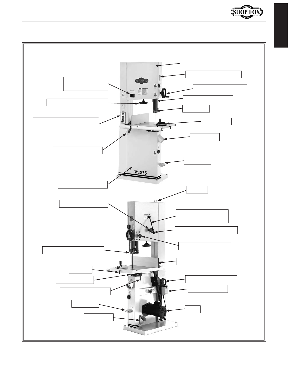
Controls and Features
Tension Indicator
Window
INTRODUCTION
Hinged Wheel Cover
Blade Tracking Window
Guide Post Handwheel
Blade Tension Handwheel
Key Switch, Start and Stop
Buttons
Fence Locking Lever
Hinged Wheel Cover
Blade Tracking Knob
Cutting Height Scale
Guide Post
Miter Gauge
Dust Port 4"
Foot Brake
Eye Bolt
Quick Release Blade
Tension Lever
Blade Tracking Lock Lever
Ball Bearing Blade Guides
Table Pin
Table Tilt Scale
Table Tilt Lock Lever
Foot Brake
Dust Port 4"
Figure 1. W1825 controls and features.
Guide Post Lock Knob
Rip Fence
Table Tilt Handwheel
Magnetic Switch
Motor
-5-
Page 8

Model W1825 (For Machines Mfd. Since 07/15)
SAFETY
OWNER’S MANUAL.
TRAINED OPERATORS ONLY.
DANGEROUS ENVIRONMENTS.
MENTAL ALERTNESS REQUIRED.
electrical components or improperly grounded
manual uses a series of symbols and signal words intended to convey the level of importance of the
safety messages. The progression of symbols is described below. Remember that safety messages by
For Your Own Safety,
Read Manual Before Operating Machine
The purpose of safety symbols is to attract your attention to possible hazardous conditions. This
SAFETY
themselves do not eliminate danger and are not a substitute for proper accident prevention measures—this responsibility is ultimately up to the operator!
NOTICE
Standard Machinery Safety Instructions
Indicates an imminently hazardous situation which, if not avoided,
WILL result in death or serious injury.
Indicates a potentially hazardous situation which, if not avoided,
COULD result in death or serious injury.
Indicates a potentially hazardous situation which, if not avoided,
MAY result in minor or moderate injury.
This symbol is used to alert the user to useful information about
proper operation of the equipment or a situation that may cause
damage to the machinery.
Read and understand this
owner’s manual BEFORE using machine.
have a higher risk of being hurt or killed. Only
allow trained/supervised people to use this
machine. When machine is not being used,
disconnect power, remove switch keys, or
lock-out machine to prevent unauthorized
use—especially around children. Make
workshop kid proof!
machinery in areas that are wet, cluttered,
or have poor lighting. Operating machinery
in these areas greatly increases the risk of
accidents and injury.
alertness is required for safe operation of
machinery. Never operate under the influence
of drugs or alcohol, when tired, or when
distracted.
Untrained operators
Do not use
Full mental
ELECTRICAL EQUIPMENT INJURY RISKS. You can
be shocked, burned, or killed by touching live
machinery. To reduce this risk, only allow an
electrician or qualified service personnel to
do electrical installation or repair work, and
always disconnect power before accessing or
exposing electrical equipment.
DISCONNECT POWER FIRST. Always disconnect
machine from power supply BEFORE making
adjustments, changing tooling, or servicing
machine. This eliminates the risk of injury
from unintended startup or contact with live
electrical components.
EYE PROTECTION. Always wear ANSI-approved
safety glasses or a face shield when operating
or observing machinery to reduce the risk of
eye injury or blindness from flying particles.
Everyday eyeglasses are not approved safety
glasses.
-6-
Page 9

Model W1825 (For Machines Mfd. Since 07/15)
WEARING PROPER APPAREL. Do not wear
HAZARDOUS
HEARING PROTECTION.
REMOVE ADJUSTING TOOLS.
INTENDED USAGE.
AWKWARD POSITIONS.
CHILDREN & BYSTANDERS.
GUARDS & COVERS.
FORCING MACHINERY. Do not force machine. It
will do the job safer and better at the rate for
loss of control. Before starting, verify machine
malfunction, leading to serious personal injury
from heated surfaces, high traffic areas, harsh
clothing, apparel, or jewelry that can become
entangled in moving parts. Always tie back
or cover long hair. Wear non-slip footwear to
avoid accidental slips, which could cause loss
of workpiece control.
DUST. Dust created while using
machinery may cause cancer, birth defects,
or long-term respiratory damage. Be aware of
dust hazards associated with each workpiece
material, and always wear a NIOSH-approved
respirator to reduce your risk.
Always wear hearing
protection when operating or observing
loud machinery. Extended exposure to this
noise without hearing protection can cause
permanent hearing loss.
machinery can become dangerous projectiles
upon startup. Never leave chuck keys,
wrenches, or any other tools on machine.
Always verify removal before starting!
intended purpose—never make modifications
without prior approval from Woodstock
International. Modifying machine or using
it differently than intended will void the
warranty and may result in malfunction or
mechanical failure that leads to serious
personal injury or death!
balance at all times when operating machine.
Do not overreach! Avoid awkward hand
positions that make workpiece control difficult
or increase the risk of accidental injury.
bystanders at a safe distance from the work
area. Stop using machine if they become a
distraction.
Only use machine for its
Tools left on
Keep proper footing and
Keep children and
which it was designed.
NEVER STAND ON MACHINE. Serious injury may
occur if machine is tipped or if the cutting
tool is unintentionally contacted.
STABLE MACHINE. Unexpected movement during
operation greatly increases risk of injury or
is stable and mobile base (if used) is locked.
USE RECOMMENDED ACCESSORIES. Consult
this owner’s manual or the manufacturer for
recommended accessories. Using improper
accessories will increase risk of serious injury.
UNATTENDED OPERATION. To reduce the risk
of accidental injury, turn machine OFF and
ensure all moving parts completely stop
before walking away. Never leave machine
running while unattended.
MAINTAIN WITH CARE. Follow all maintenance
instructions and lubrication schedules to
keep machine in good working condition. A
machine that is improperly maintained could
or death.
CHECK DAMAGED PARTS. Regularly inspect
machine for any condition that may affect
safe operation. Immediately repair or replace
damaged or mis-adjusted parts before
operating machine.
MAINTAIN POWER CORDS. When disconnecting
cord-connected machines from power, grab
and pull the plug—NOT the cord. Pulling the
cord may damage the wires inside, resulting
in a short. Do not handle cord/plug with wet
hands. Avoid cord damage by keeping it away
chemicals, and wet/damp locations.
SAFETY
accidental contact with moving parts or flying
debris—make sure they are properly installed,
undamaged, and working correctly.
Guards and covers reduce
EXPERIENCING DIFFICULTIES. If at any time
you experience difficulties performing the
intended operation, stop using the machine!
-7-
Contact Technical Support at (360) 734-3482.
Page 10

Model W1825 (For Machines Mfd. Since 07/15)
Additional Safety for Bandsaws
BLADE CONDITION. Do not operate with dull,
cracked or badly worn blade. Dull blades
require more effort to perform the cut, and
they increase the risk of kickback. Inspect
blades for cracks and missing teeth before
each use.
SAFETY
BLADE REPLACEMENT. To avoid mishaps that
could result in operator injury, make sure the
blade teeth face down toward the table and
the blade is properly tensioned and tracked
before operating.
SMALL WORKPIECE HANDLING. Always support/
feed small or narrow workpieces with a push
stick, jig, vise, or some type of clamping
fixture. Supporting these types of workpieces
by hand requires you to get closer to the
blade, which increases your risk of serious
personal injury.
BLADE SPEED. Always allow the blade to come
to full speed before starting the cut. Moving
the workpiece against a blade that is not at
full speed could cause the blade to grab the
workpiece and draw the operator's hands
into the blade.
WORKPIECE SUPPORT. If the workpiece should
unexpectedly twist during cutting, it could
kickback or draw the operator's hands into
the blade. Always keep the workpiece flat
and firm against the table when cutting. If
necessary, use a jig or other work-holding
device.
BLADE SUPPORT. The blade tension and guide/
support bearings keep the blade straight
when cutting. Always keep the blade tension
and guide thrust bearings properly adjusted
and positioned to reduce the risk of the
blade bending or breaking with the forces of
the cutting operation.
CUTTING TECHNIQUES. Plan your operation so
the blade always cuts to the outside of the
workpiece. DO NOT back the workpiece away
from the blade while the saw is running, which
could cause kickback and personal injuries. If
you need to back the workpiece out, turn the
bandsaw OFF and wait for the blade to come to
a complete stop. DO NOT twist or put excessive
stress on the blade that could damage it.
HAND PLACEMENT. Never position fingers or hands
in line with the blade. If the workpiece or your
hands slip, serious personal injury could occur.
FEED RATE. To avoid the risk of the workpiece
slipping and causing operator injury, always feed
stock evenly and smoothly. DO NOT force or twist
the blade while cutting, especially when sawing
small curves.
WORKPIECE MATERIAL. This machine is intended
for cutting natural and man-made wood products,
and laminate covered wood products. This
machine is NOT designed to cut metal, glass,
stone, tile, etc. Doing so may increase the risk of
blade breakage or machine damage.
BLADE CONTROL. To avoid serious personal injury,
DO NOT attempt to stop or slow the blade with
your hand or the workpiece. Allow the blade to
stop on its own.
UPPER BLADE GUIDE SUPPORT. To reduce the
exposure of the operator to the blade and
provide maximum support for the blade, keep
the upper blade support and guide bearings
adjusted to just clear the workpiece.
-8-
Page 11
Model W1825 (For Machines Mfd. Since 07/15)
This machine must be connected to the correct size and
type of power supply circuit, or fire or electrical damage
may occur. Read through this section to determine if an
adequate power supply circuit is available. If a correct
circuit is not available, a qualified electrician MUST install
one before you can connect the machine to power.
A power supply circuit includes all electrical equipment
between the breaker box or fuse panel in the building
and the machine. The power supply circuit used for
this machine must be sized to safely handle the fullload current drawn from the machine for an extended
period of time. (If this machine is connected to a circuit
protected by fuses, use a time delay fuse marked D.)
This machine is prewired to operate on a power supply
circuit that has a verified ground and meets the following
requirements:
The full-load current rating is the amperage a machine
draws at 100% of the rated output power. On machines
with multiple motors, this is the amperage drawn by the
largest motor or sum of all motors and electrical devices
that might operate at one time during normal operations.
or machine damage. To reduce this risk,
a dedicated circuit—
where only one machine will be running
multiple machines will be running at the
ELECTRICAL
Circuit Requirements
The machine must be properly set up
before it is safe to operate. DO NOT
connect this machine to the power
source until instructed to do so later in
this manual.
ELECTRICAL
Full-Load Current Rating
Full-Load Current Rating at 220V ................ 12 Amps
Circuit Requirements
Circuit Type ............ 220V/240V, 60 Hz, Single-Phase
Circuit Size ............................................ 15 Amps
Plug/Receptacle ................................... NEMA 6-15
Incorrectly wiring or grounding this
machine can cause electrocution, fire,
only an electrician or qualified service
personnel should do any required
electrical work on this machine.
NOTICE
The circuit requirements listed in this
manual apply to
at a time. If this machine will be
connected to a shared circuit where
same time, consult with an electrician
to ensure that the circuit is properly
sized for safe operation.
-9-
Page 12
Grounding Requirements
This machine MUST be grounded. In the event of certain
types of
a path of least resistance for electric current
order
Improper connection of the equipment-grounding
will
increase
insulation
grounding
cord or plug is necessary, do not connect the equipmentgrounding
Check with a qualified electrician or service personnel
if
or if
properly grounded.
plug is damaged or worn, disconnect it from power, and
immediately replace it with a new one.
This machine is equipped with a power cord that has
an equipment-grounding
plug
a matching
grounded in accordance with local codes and ordinances.
We do not recommend using an extension cord with
Any extension cord used with this machine must contain a
plug and receptacle, and
meet the following requirements:
the available receptacle or the machine
malfunctions or breakdowns, grounding provides
to travel—in
to reduce the risk of electric shock.
wire
the risk of electric shock. The wire with green
(with/without yellow stripes) is the equipment-
wire. If repair or replacement of the power
Model W1825 (For Machines Mfd. Since 07/15)
The machine must be properly set up
before it is safe to operate. DO NOT
connect this machine to the power
source until instructed to do so later in
this manual.
wire to a live (current carrying) terminal.
you do not understand these grounding requirements,
ELECTRICAL
you are in doubt about whether the tool is
If you ever notice that a cord or
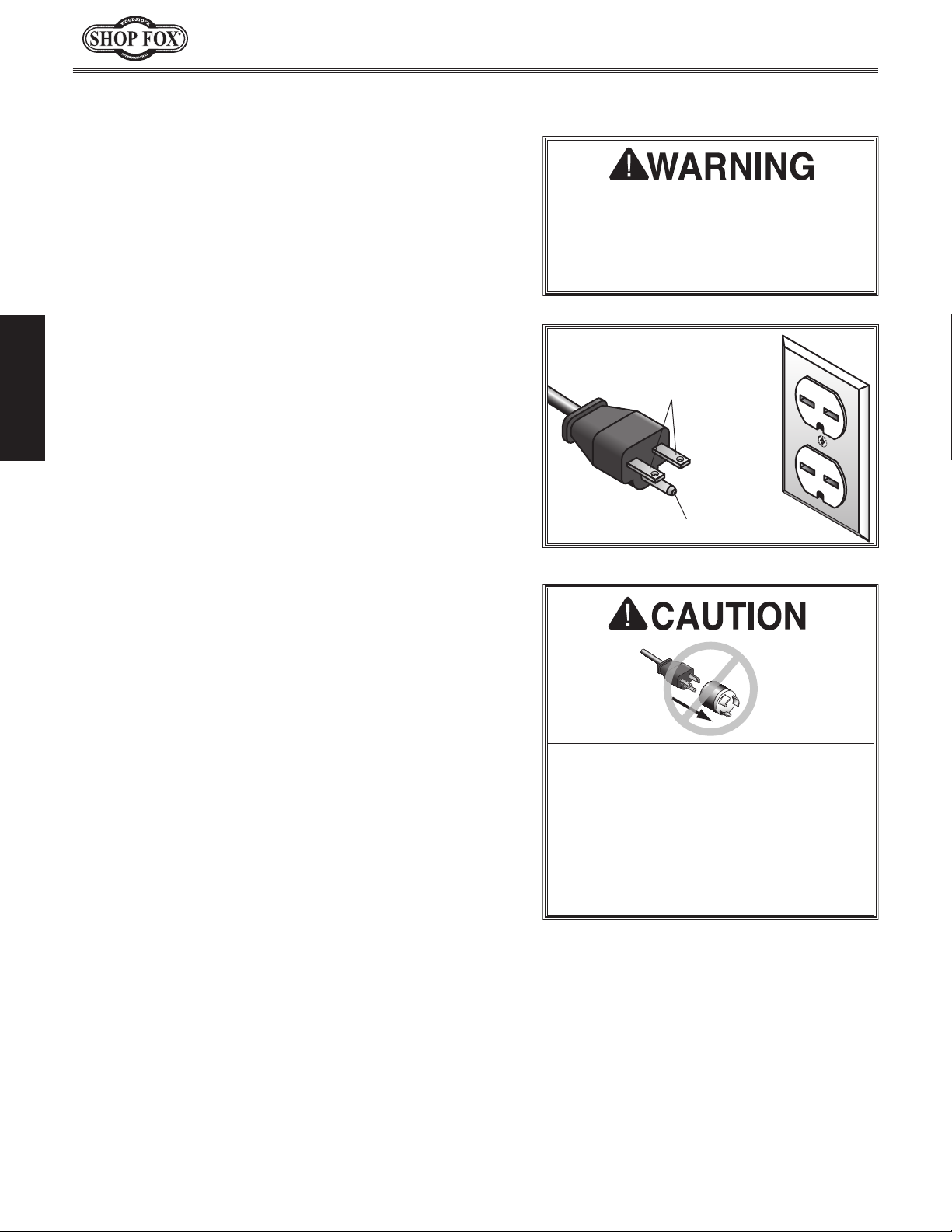
For 220V Connection
wire and NE M A 6-15 grounding
(see figure). The plug must only be inserted into
receptacle that is properly installed and
Extension Cords
this machine. Extension cords cause voltage drop, which
may damage electrical components and shorten motor
life. Voltage drop increases with longer extension cords
and smaller gauge sizes (higher gauge numbers indicate
smaller sizes).
ground wire, match the required
Minimum Gauge Size at 220V ...................... 14 AWG
Maximum Length (Shorter is Better) ................50 ft.
-10-
220V
Current Carrying Prongs
6-15 PLUG
Figure ??. NEMA 6-15 plug & receptacle.
No adapter should be used with the
required plug. If the plug does not fit
must be reconnected to a different
type of circuit, the reconnection must
be made by an electrician or qualified
service personnel and it must comply
with all local codes and ordinances.
GROUNDED
6-15 RECEPTACLE
Grounding Prong
Page 13
Model W1825 (For Machines Mfd. Since 07/15)
SETUP
Unpacking
This machine has been carefully packaged for safe
transportation. If you notice the machine has been
damaged during shipping, please contact your authorized
Shop Fox dealer immediately.
Inventory
Keep machine disconnected from
power until instructed otherwise.
The following is a description of the main components
shipped with the Model W1825. Lay the components out
to inventory them.
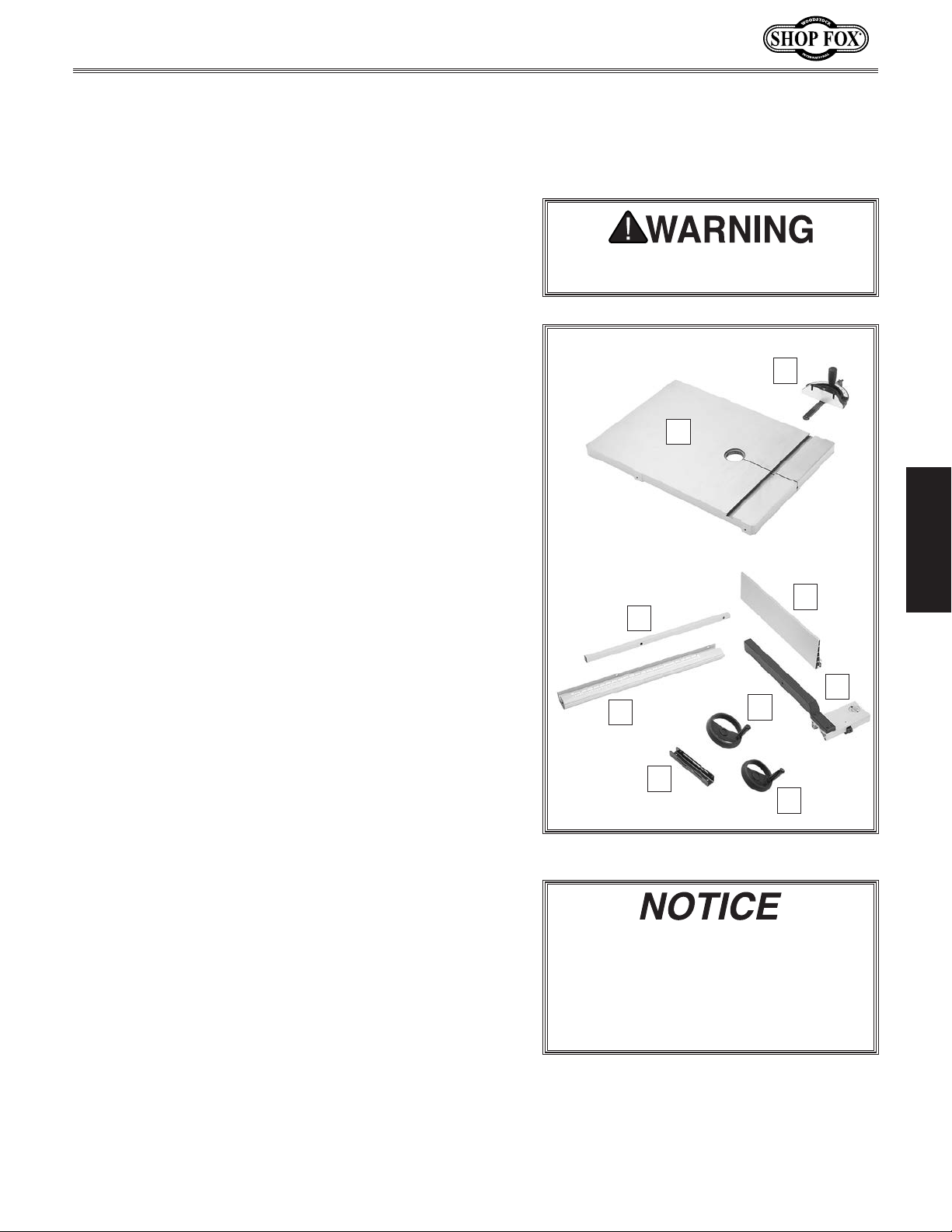
Crate Contents (Figure 3): Qty
A. Miter Gauge ............................................... 1
B. Table .........................................................1
C. Back Square Tube ..........................................1
D. Front Rail ...................................................1
E. Sliding Plate ................................................1
F. Guide Post Handwheel ....................................1
G. Table Tilt Handwheel .....................................1
H. Fence Assembly ............................................1
I. Resaw Fence................................................1
J. Foot Brake (Pre-Installed/not shown) ..................1
Hardware and Tools (not shown): Qty
• Eye Bolt M10-1.5 (may be installed) ...................1
• Flat Washers 8mm (Table, Sliding Plate, Fence) .....7
• Lock Washers 8mm (Table) ...............................4
• Hex Bolts M8-1.25 x 25 (Table) ..........................4
• Hex Bolt M8-1.25 x 55 (Sliding Plate) ..................1
• Lock Nut M8-1.25 (Sliding Plate) ........................1
• Cap Screws M6-1 x 12 (Sliding Plate) ..................2
• Hex Bolt M8-1.25 x 90 (Pos. Stop) ......................1
• Hex Nuts M8-1.25 (Pos. Stop, Fence) ..................2
• Table Pin ....................................................1
• Table Insert .................................................1
• Cap Screws M6-1 x 16 (Fence)...........................2
• Hex Bolts M6-1 x 20 (Fence) .............................2
• Fence Handle M8-1.25 x 22 (Fence) ....................1
• Rail Pad M6-1 x 20 (Fence) ..............................1
• Hex Nut M6-1 (Fence).....................................1
• Lock Handle M8-1.25 x 44 (Fence) .....................1
• Moving Plate (Fence) .....................................1
• Lock Washers 6mm (Fence, Sliding Plate) .............4
• Flat Washers 6mm (Fence, Sliding Plate) ..............4
• Hex Wrench 5mm & 8mm ...........................1 Ea.
• Open End Wrench 10 x 13mm ...........................1
A
B
I
C
H
D
E
Figure 3. W1825 inventory components.
If you can't find an item on this list,
check the mounting location on the
machine or examine the packaging
materials carefully. Occasionally we
pre-install certain components for safer
shipping.
G
F
SETUP
-11-
Page 14
To prevent
machine, the factory has coated t
of your machine
compound
I
be difficult to
coating is as easy as possible, please gather the correct
cleaner, lubricant, and tools listed below:
• Cleaner/degreaser
and grease
• Safety glasses & disposable gloves
•
• Disposable Rags
To
1.
2.
3
4
5
6
immediately coat with a quality metal protectant.
Cleaning Machine
corrosion during shipment and storage of your
with a heavy-duty rust prevention
.
f you are unprepared or impatient, this compound can
remove. To ensure that the removal of this
designed to remove storage wax
Solvent brush or paint brush
remove rust preventative coating, do these steps:
DISCONNECT MACHINE FROM POWER!
Model W1825 (For Machines Mfd. Since 07/15)
he bare metal surfaces
Gasoline and petroleum
products have low flash
points and can explode
or cause fire if used to
clean machinery. Avoid
using these products
to clean machinery.
Many cleaning solvents
are toxic if inhaled.
Minimize your risk
by only using these
products in a well
ventilated area.
SETUP
Put on safety glasses and disposable gloves.
. Coat the rust preventative with a liberal amount of
cleaner/degreaser, then let it soak for 5–10 minutes.
. Wipe off surfaces. If your cleaner/degreaser is
effective, the coating will wipe off easily.
Tip: An easier way to clean off thick coats of rust
preventative from flat surfaces is to use a PLASTIC
paint scraper to scrape off the majority of the
coating before wiping it off with your rag. (Do
not use a metal scraper or you may scratch your
machine.)
. Repeat cleaning steps as necessary until all of the
compound is removed.
. To prevent rust on freshly cleaned surfaces,
In a pinch, automotive degreasers,
mineral spirits or WD•40 can be used
to remove rust preventative coating.
Before using these products, though,
test them on an inconspicuous area of
your paint to make sure they will not
damage it.
-12-
Page 15
Model W1825 (For Machines Mfd. Since 07/15)
Weight Load
Refer to the
weight of your machine. Make sure that the
surface upon which the machine is placed will
bear the weight of the machine, additional
equipment that may be installed on the
machine, and the heaviest workpiece that will
be used. Additionally, consider the weight of
the operator and any dynamic loading that may
occur when operating the machine.
Space Allocation
Consider the largest size of workpiece that
will be processed through this machine and
provide enough space around the machine
for adequate operator material handling or
the installation of auxiliary equipment. With
permanent installations, leave enough space
around the machine to open or remove doors/
covers as required by the maintenance and
service described in this manual.
required space allocation.
Physical Environment
The physical environment where your machine is
operated is important for safe operation and the
ambient temperature range exceeds 41°–104°F;
(non-condensing); or the environment is subject
source. Make sure all power cords are protected
chemicals, or other hazards. Make sure to leave
Machine Specifications for the
longevity of its components. For best results,
operate this machine in a dry environment
that is free from excessive moisture, hazardous
chemicals, airborne abrasives, or extreme
conditions. Extreme conditions for this type
of machinery are generally those where the
the relative humidity range exceeds 20–95%
to vibration, shocks, or bumps.
Electrical Installation
Place this machine near an existing power
from traffic, material handling, moisture,
See below for
Children or untrained people
may be seriously injured by this
machine. Only install in an access
restricted location.
access to a means of disconnecting the power
source or engaging a lockout/tagout device.
Lighting
Lighting around the machine must be adequate
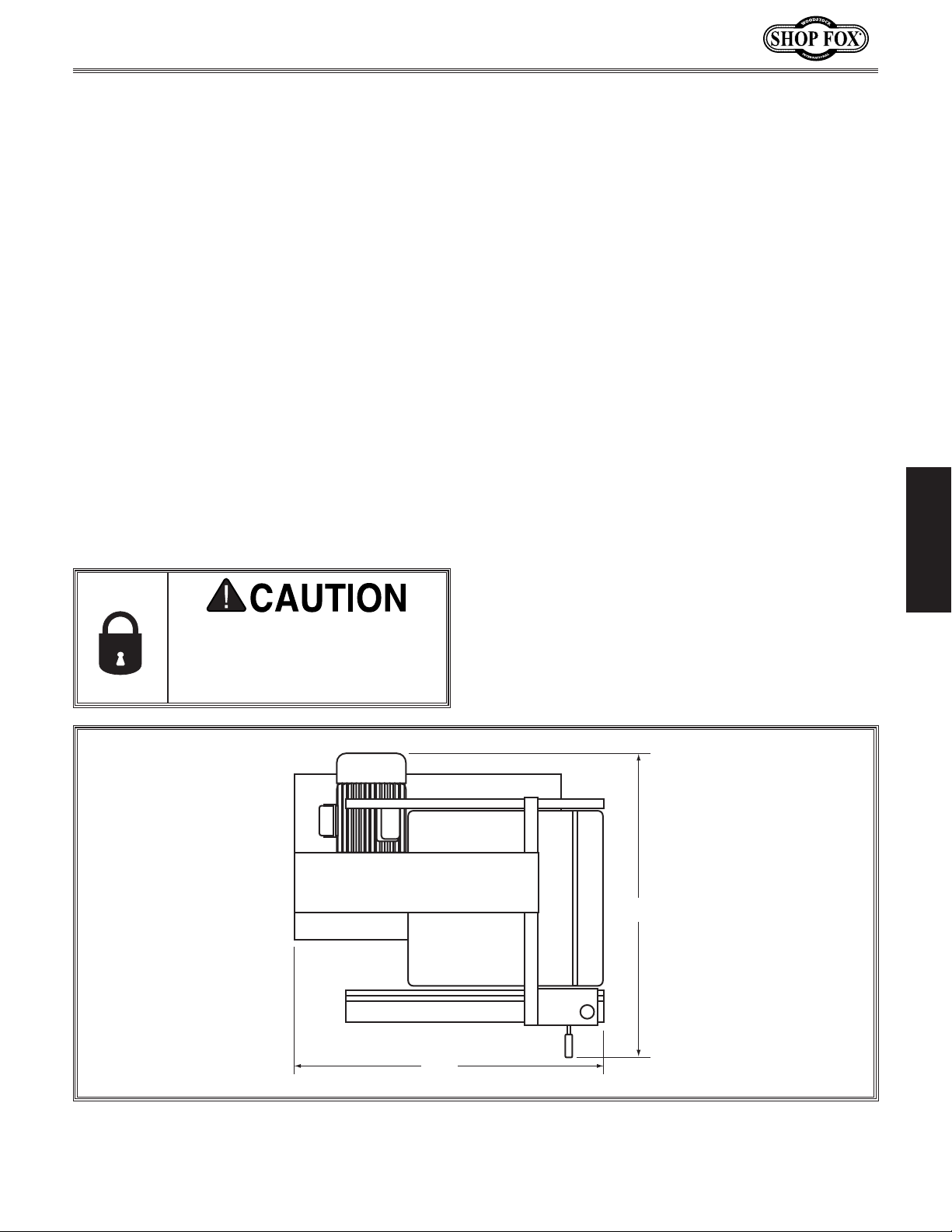
36"
enough that operations can be performed
safely. Shadows, glare, or strobe effects that
may distract or impede the operator must be
eliminated.
32"
SETUP
Figure 4. W1825 working clearances.
-13-
Page 16
Lifting & Moving
Model W1825 (For Machines Mfd. Since 07/15)
Take special care when moving this bandsaw. Leave it
attached to the pallet until it is in or close to its final
location. This provides a stable platform while moving
the machine. Then use one of the following methods to
remove the pallet and set the bandsaw in position.
To place the bandsaw using the eye bolts, do these
steps:
1. Unbolt the bandsaw from the pallet.
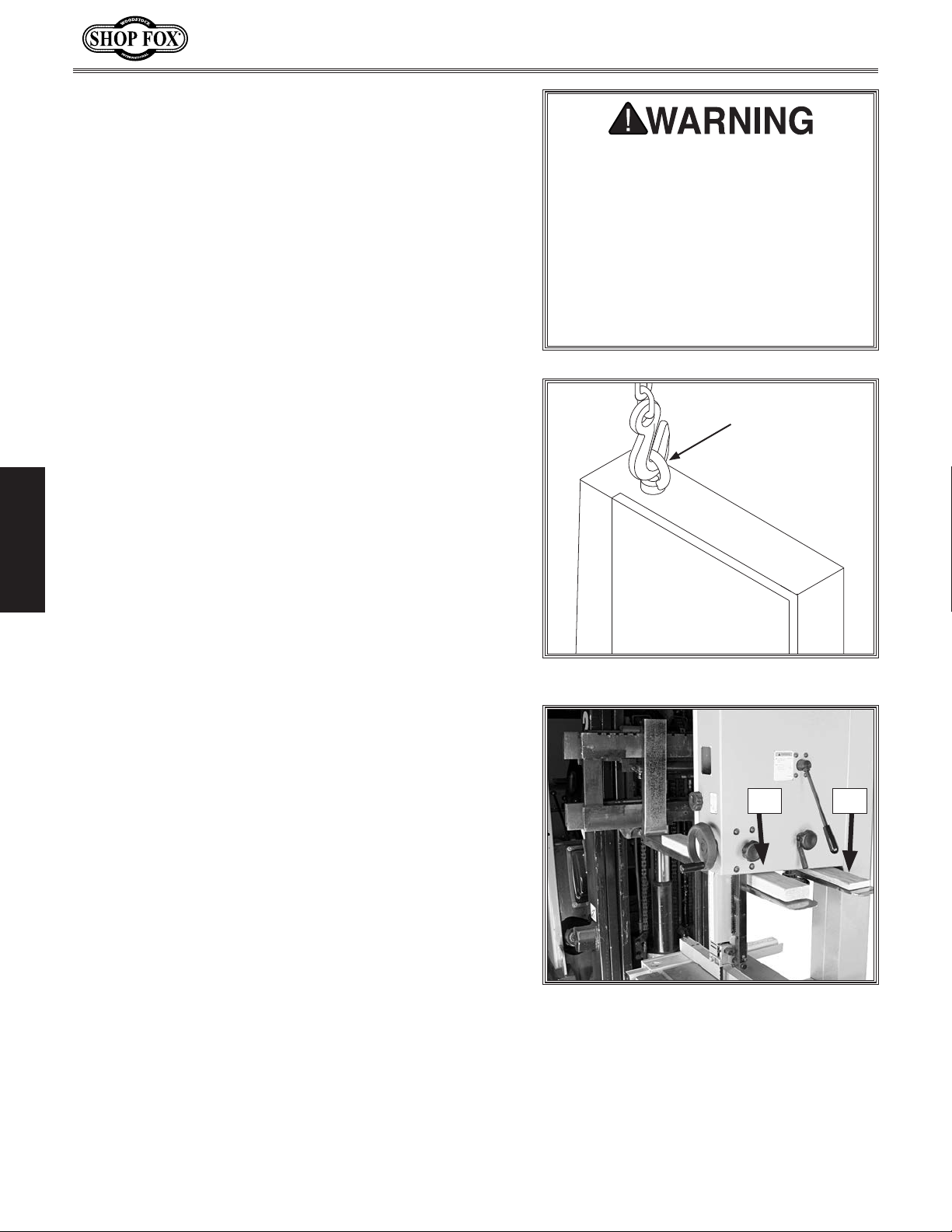
2. Install the eye bolt shown in Figure 5, make sure
it is threaded all the way in, then place the lifting
hook through the eye bolt and lift slowly with a
forklift.
3. Remove the pallet and slowly set the bandsaw into
position.
To place the bandsaw using wood shims, do these
steps:
SETUP
1. Carefully place the forklift forks under the head and
install a 1x4 shim between the head and the left
fork and a 2x4 shim between the head and right fork
so the bandsaw is level, as shown in Figure 6.
2. Unbolt the bandsaw from the pallet.
This is a heavy machine. Serious personal injury may occur if safe moving
methods are not followed. To be safe,
you will need assistance and a forklift
or a hoist when removing the machine
from the crate. Use a chain or a lifting strap with a minimum of 1000 lbs.
lifting capacity. If the chain or lifting
strap breaks, serious personal injury
may occur.
Eye Bolt
Figure 5. Lifting the bandsaw.
3. Lift the bandsaw off of the pallet, remove the
pallet, and slowly set the bandsaw into position.
Note: If you are concerned about your forklift
forks hitting the tension handwheel, remove the
handwheel, then re-install it after lifting.
2x4 1x4
Figure 6. Example of lifting bandsaw with
forklift using wood shims.
-14-
Page 17
Model W1825 (For Machines Mfd. Since 07/15)
alternatives to lag shield anchors; however, they will
Mounting to Shop Floor
Although not required, we recommend that you mount
your new machine to the floor. Because this is an optional
step and floor materials may vary, floor mounting
hardware is not included. Generally, you can either bolt
your machine to the floor or mount it on machine mounts.
Both options are described below. Whichever option you
choose it will be necessary to use a precision level to
level your machine.
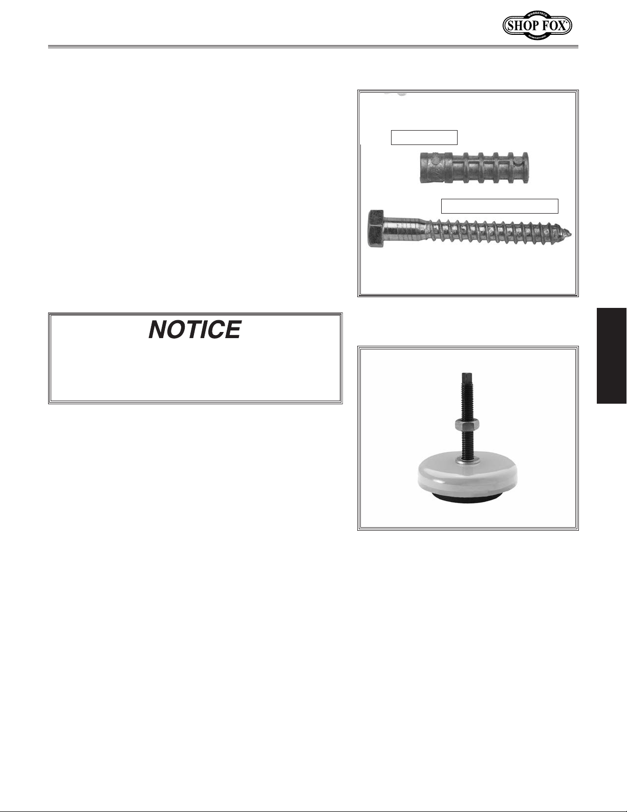
Bolting to Concrete Floors
Lag shield anchors with lag bolts and anchor studs
(Figure 7) are two popular methods for anchoring an
object to a concrete floor. We suggest you research the
many options and methods for mounting your machine
and choose the best that fits your specific application.
Anchor studs are stronger and more permanent
Anchor Stud
Lag Screw and Anchor
Figure 7. Typical fasteners for mounting to
concrete floors.
SETUP
stick out of the floor, which may cause a tripping
hazard later if you decide to move your machine.
Using Machine Mounts
Using machine mounts, shown in Figure 8, gives the
advantage of fast leveling and vibration reduction. The
large size of the foot pads distributes the weight of the
machine to reduce strain on the floor.
Figure 8. Machine mount example.
-15-
Page 18
Assembly
To assemble the bandsaw, do these steps:
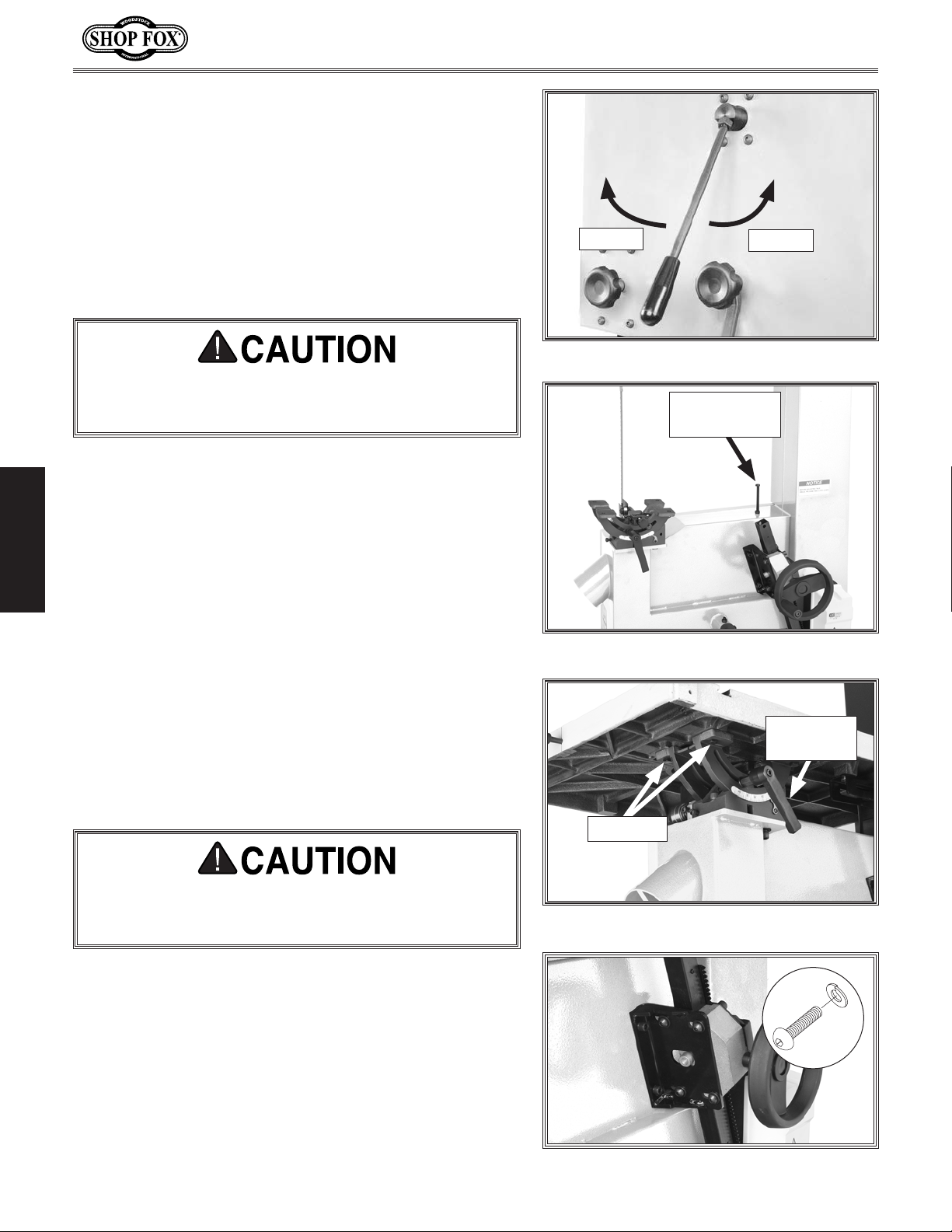
1. Loosen the blade tension by rotating the quick
release tension lever clockwise, as shown in
Figure 9.
2. Open the upper and lower covers and remove the
blade.
Saw blades are sharp. Handling them may cause
laceration injuries. To reduce this risk, wear leather
gloves when handling.
3. Thread the M8-1.25 hex nut halfway onto the
M8-1.25 x 90 hex bolt (positive stop bolt).
Model W1825 (For Machines Mfd. Since 07/15)
Loosen
Figure 9. Quick-release tension lever.
Positive Stop
Tighten
Bolt
4. Thread the positive stop bolt into the threaded hole
SETUP
on the bandsaw body, as shown in Figure 10. Ensure
the head of the bolt is not higher than the trunnions.
Note: Instructions for adjusting the table to the
blade are covered in the Positive Stop section on
Page 31.
5. Ensure that the table tilt lever is tightened and the
trunnion is secure before proceeding to the next
step.
6. With the help of another person, lift the table onto
the trunnion.
The table is HEAVY. Get help when lifting and use
proper lifting techniques to reduce the risk of
injury.
Figure 10. Positive stop bolt location.
Table Lock
Lever
Hex Bolts
Figure 11. Mounting the table.
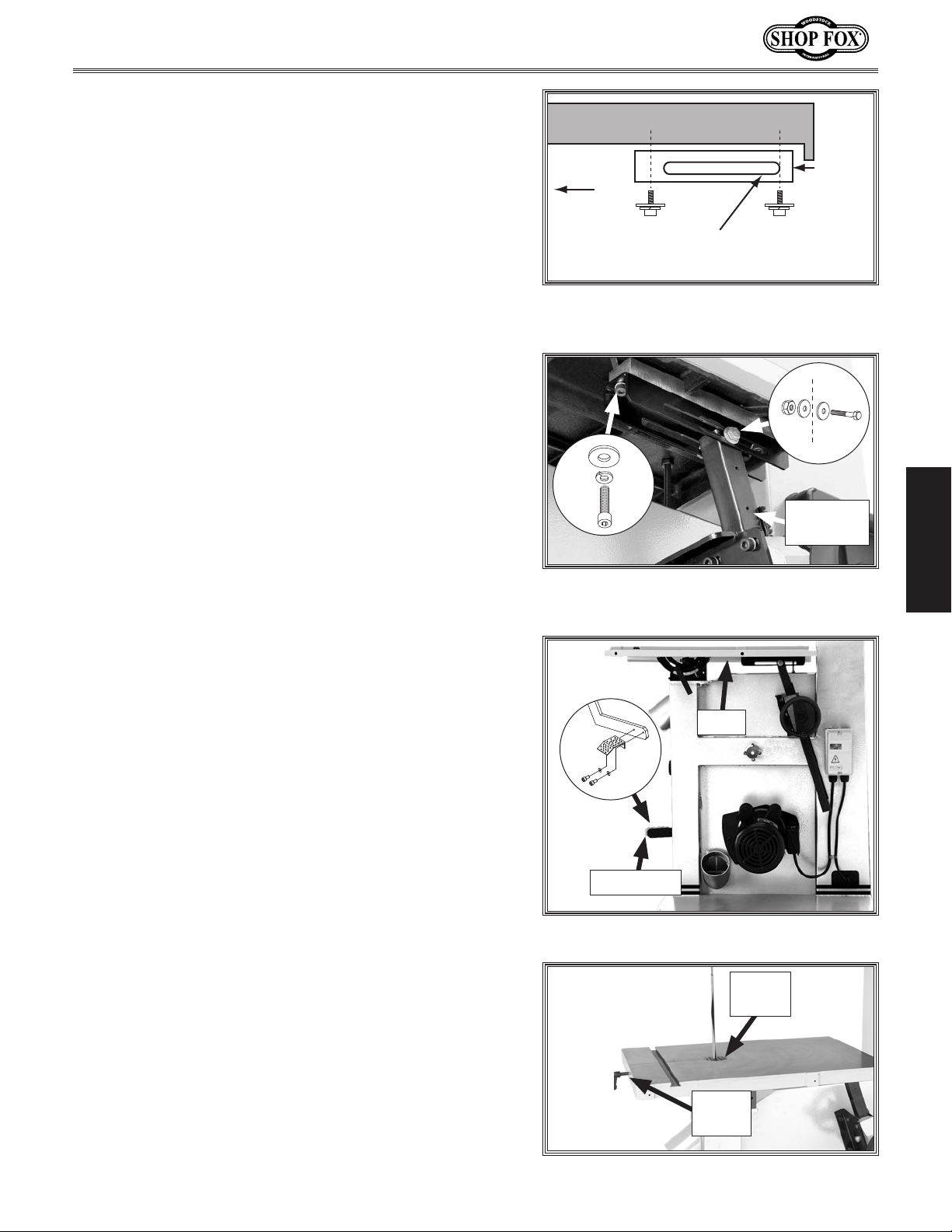
7. Secure the table to the trunnion using (4) M8-1.25
x 25 hex bolts, 8mm lock washers, and 8mm flat
washers, as shown in Figure 11.
8. Loosen the (4) M8-1.25 x 20 button head cap screws
that secure the guide bracket to the guide bracket
plate shown in Figure 12.
-16-
x 4
Figure 12. Table tilt assembly screws.
Page 19
Model W1825 (For Machines Mfd. Since 07/15)
9. Attach the sliding plate to the underside of the
table, with the channel positioned to the right, using
(2) M6-1 x 12 cap screws, 6mm lock washers, and
6mm flat washers, as shown in Figures 13–14.
Tip: Install hardware loosely until all components
are in place. This allows components to properly
seat when you finish-tighten the hardware.
10. Secure the table tilt tube to the sliding plate with
(1) M8-1.25 x 55 hex bolt, 8mm flat washer, and
M8-1.25 lock nut. Do NOT overtighten—doing so will
prevent the table tilt mechanism from operating
properly (see Figure 14).
11. Retighten the (4) M8-1.25 x 20 button head cap
screws loosened in Step 8.
12. Finish-tighten all other table hardware. The table
tilt assembly should look like Figure 15.
13. Install the foot brake using (2) M6-1 x 16 cap screws,
6mm lock washers, and 6mm lock washers (see
Figure 16).
Note: The foot brake and its mounting hardware is
attached to the brake lever for shipping.
Table
Trunnion
Channel Positioned
to the Right
Figure 13. Sliding plate channel
alignment.
x 2
Table Tilt
Tube
Figure 14. Table tilt tube secured to
sliding plate.
Sliding
Plate
x 1
SETUP
14. Re-install the blade (refer to Changing Blades on
Page 41 for detailed instructions).
15. Install the table insert and table pin (see Figure 16).
Note: The table pin keeps the table aligned and
should always be replaced after blade changes or
other maintenance that requires its removal.
Table
Foot Brake
Figure 15. Table and foot brake installed.
Table
Insert
Table
Pin
-17-
Figure 16. Table pin and insert installed.
Page 20
Model W1825 (For Machines Mfd. Since 07/15)
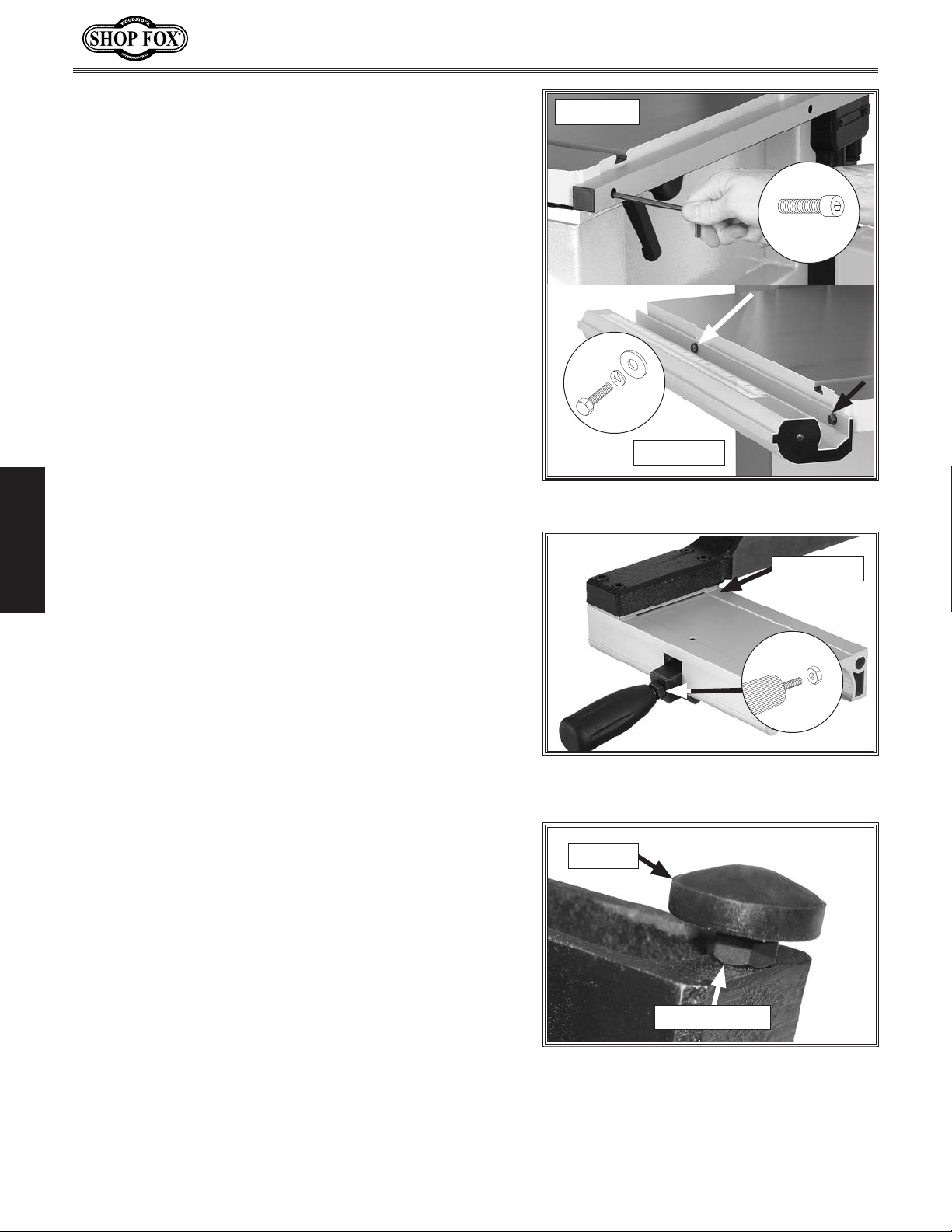
16. Attach the rear fence rail to the table with the (2)
M6-1 x 16 cap screws, as shown in Figure 17.
17. Attach the front rail with the (2) M6-1 x 20 hex
bolts, 6mm lock washers, and 6mm flat washers,
(see Figure 17).
18. Install an M8-1.25 hex nut on the fence handle, then
SETUP
thread the handle into the fence assembly, (see
Figure 18). Tighten the hex nut against the fence
pivot block to secure the handle.
Rear View
x 2
x 2
Front View
Figure 17. Rail installation.
Pivot Block
19. Thread the M6-1 hex nut onto the rail pad, then
thread the rail pad into the fence (see Figure 19).
x 1
Figure 18. Handle installed on fence
assembly.
Rail Pad
M6-1 Hex Nut
Figure 19. Installed rail pad.
-18-
Page 21
Model W1825 (For Machines Mfd. Since 07/15)
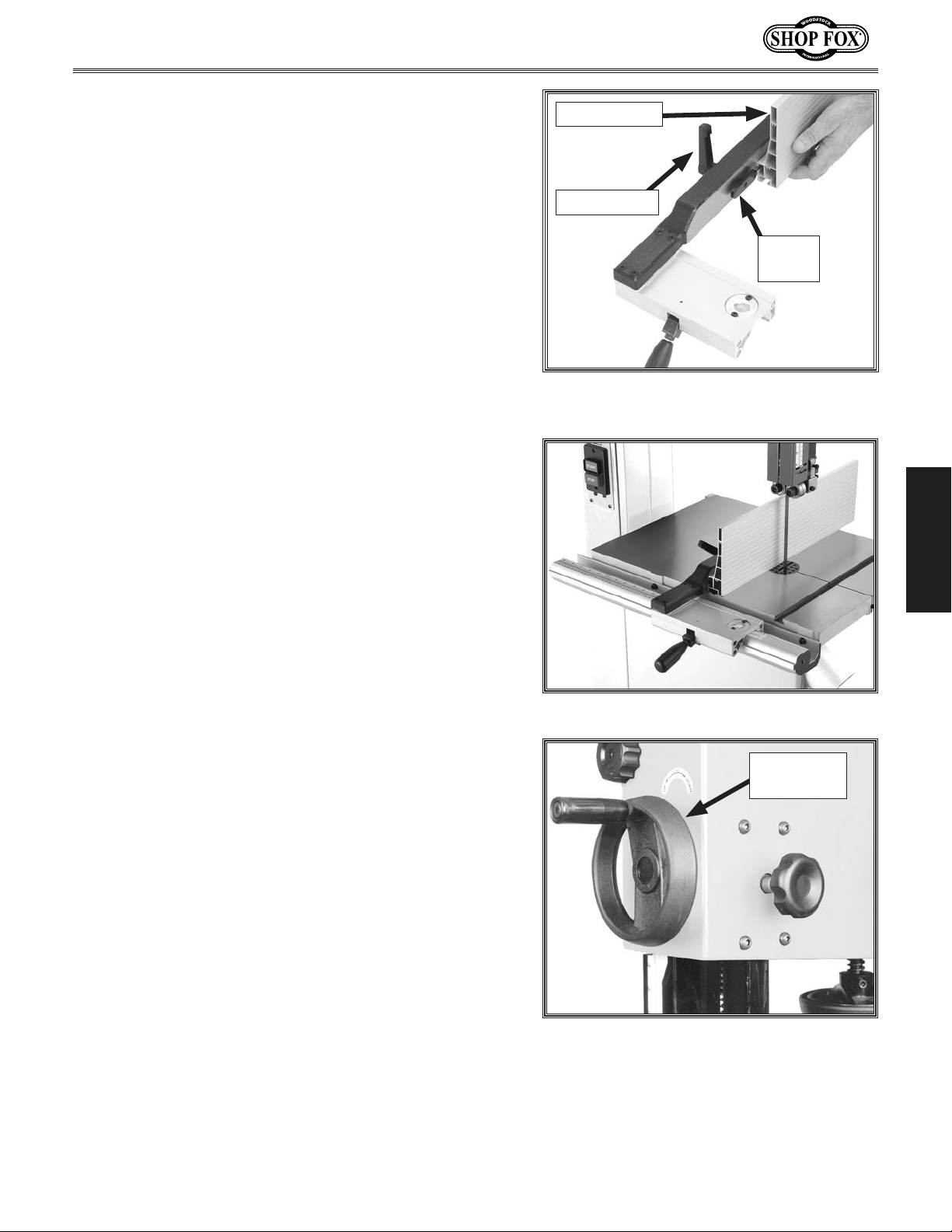
20. Place an 8mm flat washer on the lock handle,
slide it through the hole in the fence, then thread
the moving plate onto the end of the lock handle
threads.
Resaw Fence
21. Slide the resaw fence over the moving plate, as
shown in Figure 20, so the moving plate fits inside
the channel of the resaw fence.
22. Tighten the lock handle.
23. Pull the fence handle up and place the fence
assembly on the front rail (see Figure 21).
24. Push the fence handle down to lock the fence
assembly in place.
Lock Handle
Moving
Plate
Figure 20. Attaching resaw fence to
standard fence.
SETUP
25. Adjust the rail pad until there is an even gap
between the bottom of the fence and the table,
then tighten the hex nut against the fence.
26. Secure the guide post handwheel onto the
handwheel shaft with the included set screw (see
Figure 22).
Figure 21. Correctly installed fence.
Guide Post
Handwheel
Figure 22. Guide post handwheel
installed.
-19-
Page 22
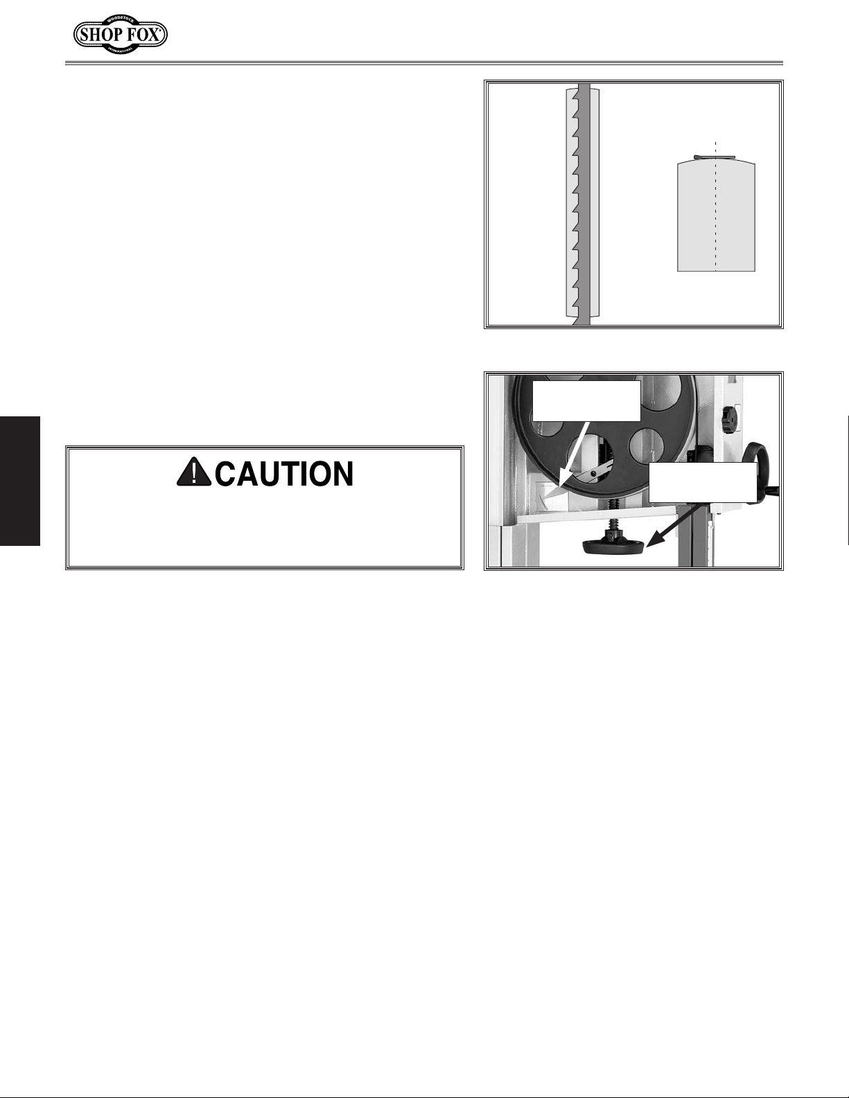
Blade Tracking
Blade Centered
on Peak of Crown
Blade
Centered
on Wheel
CENTER TRACKING
"Tracking" refers to how the blade rides on the bandsaw
wheels. The tilt of the upper wheel determines how the
blade tracks. Proper tracking is important for maintaining
bandsaw adjustments, achieving correct blade tension,
and cutting accurately. Improper tracking reduces cutting
accuracy, causes excess vibrations, and places stress on
the blade and other bandsaw components.
This bandsaw has crowned wheels. As the wheels spin,
the blade naturally tracks to the highest point of the
crown at the center of the wheel (see Figure 23).
Model W1825 (For Machines Mfd. Since 07/15)
The wheels on the W1825 were aligned at the factory,
so center tracking is the only adjustment that needs to
be performed when the saw is new. This adjustment is
necessary before turning the saw ON or performing other
adjustments.
SETUP
The cast iron spokes may have sharp edges and
the blade teeth may extend beyond the edge of
the wheel, creating a laceration hazard. Be careful
when turning the wheels by hand.
To center track the blade, do these steps:
1. DISCONNECT BANDSAW FROM POWER!
2. Make sure the upper and lower blade guides are
adjusted away from the blade.
3. Engage the quick-tension lever and turn the blade
tension handwheel until the tension scale (see
Figure 24) reads between 4 and 6.
Figure 23. Center tracking profiles.
Blade Tension
Scale
Blade Tension
Handwheel
Figure 24. Blade tensioning controls.
-20-
Page 23
Model W1825 (For Machines Mfd. Since 07/15)
4. Spin the upper wheel by hand at least three times
and watch how the blade rides on the crown of the
wheel. Refer to Figure 23 for an illustration of this
concept.
— If the blade rides in the center of the upper
wheel and is centered on the peak of the wheel
crown, then the bandsaw is already tracked
properly and no further adjustments are needed at
this time.
— If the blade does not ride in the center of the
upper wheel and is not centered on the peak
of the wheel crown, then continue with the
following steps.
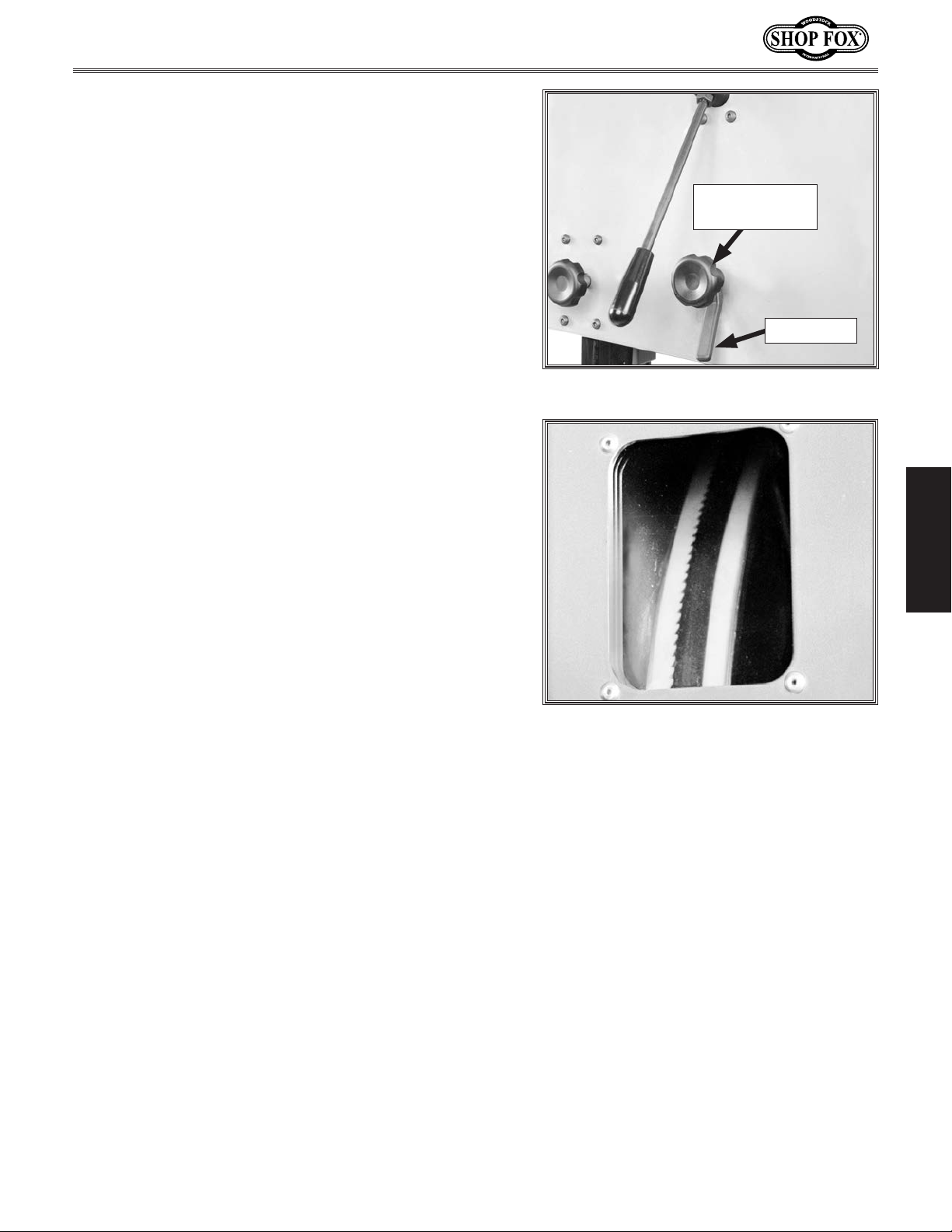
5. Loosen the lock lever (see Figure 25) so that the
blade tracking knob can rotate.
6. Spin the upper wheel with one hand and rotate the
blade tracking knob with the other hand to make
sure the blade rides in the center of the bandsaw
wheel tire.
7. Tighten the lock lever and close the upper wheel
cover.
Additional "fine tune" tracking may be done after the
bandsaw is connected to power. This is done while the
bandsaw is running, using the wheel tilt knob to make
small adjustments while watching the blade tracking
through the window shown in Figure 26.
Blade Tracking
Knob
Lock Lever
Figure 25. Blade tracking controls.
SETUP
Figure 26. Blade tracking window.
-21-
Page 24

Dust Collection
Recommended CFM at each Dust Port: ......... 400 CFM
Do not confuse this CFM recommendation with the rating
of the dust collector. To determine the CFM at the
dust port, you must take into account many variables,
including the CFM rating of the dust collector, the length
of hose between the dust collector and the machine, the
amount of branches or Y's, and the amount of other open
lines throughout the system. Explaining this calculation
is beyond the scope of this manual. If you are unsure of
your system, consult an expert or purchase a good dust
collection "how-to" book.
To connect a dust collection hose, do these steps:
1. Fit a 4" dust hose over each dust port and secure
them in place with a hose clamp (see Figure 27).
2. Tug the hoses to make sure they do not come off.
Note: A tight fit is necessary for proper
SETUP
performance.
Model W1825 (For Machines Mfd. Since 07/15)
Figure 27. Dust hoses connected to dust
ports.
DO NOT operate this machine without an adequate dust collection system. This machine creates substantial
amounts of wood dust while operating.
Failure to use a dust collection system
can result in short and long-term respiratory illness.
Power Connection
After you have completed all previous setup instructions
and circuit requirements, the machine is ready to be
connected to the power supply.
To avoid unexpected startups or property damage, use
the following steps whenever connecting or disconnecting
the machine.
Connecting Power
1. Turn the machine power switch OFF.
2. Insert the power cord plug into a matching power
supply receptacle. The machine is now connected to
the power source.
Disconnecting Power
1. Turn the machine power switch OFF.
2. Grasp the molded plug and pull it completely out
of the power supply receptacle. DO NOT pull by the
cord as this may damage the wires inside.
-22-
Page 25

Model W1825 (For Machines Mfd. Since 07/15)
Test Run
Once assembly is complete, the next step is to test run
your machine to make sure it runs properly and is ready
for regular operation.
The test run consists of verifying the following: 1) The
motor powers up and runs correctly, 2) the OFF button
safety feature works correctly, 3) the foot brake operates
correctly, and 4) the switch key works correctly.
Always disconnect the bandsaw from
power before investigating or attempting
to correct a problem. Failure to do so
could lead to serious personal injury.
If, during the test, any safety feature does not work as
described, or you cannot easily locate the source of an
unusual noise or vibration, then immediately disconnect
the bandsaw from power, and refer to Troubleshooting
on Page 59. Make sure you resolve the problem before
proceeding with additional steps in this test run.
To test run the machine, do these steps:
1. Make sure you understand the safety instructions
at the beginning of the manual, and verify that the
machine is set up properly.
2. Clear away all tools and objects used during setup
are from the machine.
3. Connect the machine to the power source.
4. Turn the switch key to "1" and reset the Stop button
by turning it clockwise until it pops out.
5. Press the ON button to turn the bandsaw ON (see
Figure 28).
— When operating correctly, the bandsaw runs
smoothly with little or no vibration or rubbing
noises.
— Investigate and correct strange or unusual noises
or vibrations before operating the bandsaw
further.
6. Press the OFF button to stop the machine.
7. WITHOUT resetting the OFF button, press the ON
button. The machine should not start.
— If the machine does not start, the OFF button
safety feature is working correctly.
Switch
Key
On Button
Stop
Button
SETUP
Figure 28. W1825 switch key and ON/OFF
switch.
8. Turn the bandsaw ON and allow it to
reach full speed, then press the foot
brake completely.
— If the bandsaw blade stops, the foot
brake is working correctly; continue
to the next step.
— If the bandsaw blade does not stop
moving, the foot brake feature is
not working correctly. Immediately
disconnect power.
9. Turn the switch disabling key to "0"
(see Figure 28).
10. Try to turn the machine ON.
— If the bandsaw does not start, the
switch disabling feature is working
as designed. Proceed to Step 6.
— If the bandsaw starts, immediately
disconnect power. The switch
disabling feature is not working
correctly.
— If the machine does start (with the OFF button
pushed in) the OFF button safety feature is not
working correctly.
-23-
Page 26

Tensioning Blade
Model W1825 (For Machines Mfd. Since 07/15)
A properly tensioned blade is essential for making
accurate cuts, maximizing the life of the blade, and
making other bandsaw adjustments. However, it will not
compensate for cutting problems caused by too rapid of
a feed rate, hardness variations between workpieces, and
improper blade selection.
Blade tensioning method is a matter of preference.
The flutter method and the deflection method are
described below. Either method safely tensions the blade.
Experience and personal preference will help you decide
which method your prefer. Optimal cutting results for any
workpiece are a combination of correct blade selection,
proper blade tension, and an appropriate feed rate.
The Flutter Method
1. DISCONNECT BANDSAW FROM POWER!
2. Make sure the blade is properly center tracking as
instructed in the Blade Tracking on Page 20.
SETUP
3. Raise the guide post all the way, and move the upper
and lower guide bearings away from the blade.
4. Engage the blade tension quick release lever to
apply tension to the blade.
Improper blade tension is unsafe,
produces inaccurate and inconsistent
results, and introduces unnecessary
wear on bandsaw components. Overtensioning the blade increases the
chance of the blade breaking or wheel
misalignment. Under-tensioned blades
wander excessively while cutting
and will not track properly during
operation.
Tensioning the blade according to the
blade tension scale before the Tes t R u n
section gave an approximate tension
for completing the bandsaw setup. The
following procedures tension the blade
for operation.
Blade
Tension
Scale
5. Connect the bandsaw to power, and turn the
bandsaw ON.
6. Using the blade tension adjustment knob, slowly
decrease blade tension until you see the blade start
to flutter.
7. Slowly increase the tension until the blade stops
fluttering, then tighten the blade tension adjustment
knob and additional
8. Turn the bandsaw OFF and disconnect the bandsaw
from power.
9. Look at what the tension gauge reads and use that
as a guide for tensioning that specific blade in the
future.
10. Re-adjust blade guides as described in Adjusting
Blade Guide Bearings and Adjusting Support
Bearings on Pages 26–27.
1
⁄8 to 1⁄4 of a turn.
Blade Tension
Handwheel
Figure 29. Front blade tensioning controls.
Do not rely on this setting for other
blades or for long periods of time
because all blades require specific
tensioning and stretch with use. If you
notice a decrease in performance at
the setting repeat this procedure.
-24-
Page 27

Model W1825 (For Machines Mfd. Since 07/15)
The Deflection Method
The deflection method is more subjective than the flutter method. Each blade will deflect differently and every
user will determine what "moderate pressure" means. The
following are general guidelines for tensioning the blade
with this method.
To tension the bandsaw blade, do these steps:
1. DISCONNECT BANDSAW FROM POWER!
2. Make sure the blade is properly tracking as
instructed in the Blade Tracking section on Page 20.
3. Raise the guide post all the way, and move the upper
and lower guide bearings away from the blade.
4. Engage the blade tension quick release lever to
apply tension to the blade.
With extended use, the blade tensioning
system may need to be reset. Refer to
Adjusting Tension Lever on Page 50 in
the Service section in this manual for
details.
5. Using moderate pressure, push the center of the
blade sideways.
1
— If the blade deflects approximately
⁄4" it is
properly tensioned. Proceed to Step 6.
1
— If the blade deflects less than
⁄4" it is over-
tensioned. Turn the blade tensioning knob
counterclockwise two full turns and repeat Step 6.
1
— If the blade deflects more than
⁄4", the blade is
not properly tensioned. Apply tension to the blade
incrementally and repeat Step 5 until properly
tensioned.
6. Re-adjust blade guides as described in Adjusting
Blade Guide Bearings and Adjusting Blade Support
Bearings on Pages 26–27.
SETUP
-25-
Page 28

Adjusting Blade Guide
Bearings
The blade guides provide side-to-side support to keep
the blade straight while cutting. The blade guides are
adjustable in two ways—forward/backward and sideto-side. Make sure the blade is tracking properly and
is correctly tensioned before adjusting the blade guide
bearings.
To adjust the upper blade guides, do these steps:
Model W1825 (For Machines Mfd. Since 07/15)
Guide Block
Assembly Cap
Screws
Blade Guide
Bearings
1. DISCONNECT BANDSAW FROM POWER!
2. Familiarize yourself with the upper blade guide
controls shown in Figures 30–31.
3. Loosen the lateral adjustment rod bolt, loosen
the support bearing adjustment shaft cap screw,
and adjust the blade guides until the edges of
the bearings are
illustrated in Figure 32.
1
/16" behind the blade gullets, as
SETUP
1
Note: The
blades it may not be possible. In such cases, adjust
the guide bearings as far forward to the blade
gullets as possible, and still maintain the proper
support bearing spacing adjustment.
⁄16" spacing is ideal, although with larger
NOTICE
Make sure that the blade teeth will not contact the
guide bearings when the blade is pushed against the
rear support bearing when cutting or the blade teeth
will be ruined.
Bearing Rotation
Adjustment Cap
Screw
Figure 30. Upper blade guide controls
(rear view).
Support Bearing
Adjustment
Shaft Cap Screw
Knurled Knob
Bearing
Rotation
Adjustment
Cap Screw
Figure 31. Upper blade guide controls
(front view).
Knurled
Knob
4. Tighten the lateral adjustment rod cap screw.
5. Loosen the bearing rotation adjustment cap screws
on both sides of the blade.
6. Rotate the knurled knobs to position the bearings
0.004" away from the blade.
Note: 0.004" is approximately the thickness of a
dollar bill.
7. Tighten both of the bearing rotation adjustment cap
screws to lock the blade guide bearings in position.
-26-
Bearings
1
⁄16"
Blade
Gullet
Figure 32. Lateral adjustment of blade
guides.
Page 29

Model W1825 (For Machines Mfd. Since 07/15)
NOTICE
Whenever changing a blade or adjusting tension
and tracking, the upper and lower blade support
bearings and guide bearings must be properly
adjusted and locked before cutting operations.
To adjust the lower blade guides, do these steps:
1. DISCONNECT BANDSAW FROM POWER!
Lower
Guide Bearing
2. Familiarize yourself with the lower blade guide
controls shown in Figures 33.
3. Follow the instructions for adjusting the upper blade
guides on Page 26 in a similar manner for adjusting
the lower blade guides.
Adjusting Support
Bearings
NOTICE
Whenever changing a blade or adjusting tension
and tracking, the upper and lower blade support
bearings and blade guide bearings must be properly
adjusted before cutting operations.
The support bearings are positioned behind the blade
for support during cutting operations, because the blade
is typically pushed back with the pressure from the
advancing workpiece. Proper adjustment of the support
bearings is an important part of making accurate cuts and
also keeps the blade teeth from coming in contact with
the guide bearings while cutting. Make sure the blade
is tracking properly and that it is correctly tensioned
before adjusting the upper and lower support bearings.
Guide Block
Assembly Cap Screw
Figure 33. Lower blade guide controls.
Guide Block
Assembly Cap
Screws
Bearing Rotation
Adjustment
Cap Screw
Figure 34. Upper blade guide controls
(rear view).
Support Bearing
Adjustment Cap
Screw
Blade Guide
Bearings
Knurled
Knob
SETUP
To adjust the upper support bearing, do these steps:
1. DISCONNECT BANDSAW FROM POWER!
2. Familiarize yourself with the upper support bearing
controls shown in Figures 34–35.
-27-
Knurled Knob
Bearing Rotation
Adjustment Cap
Screw
Figure 35. Upper blade guide controls
(front view).
Page 30

3. Loosen the guide block assembly cap screws and
rotate the blade guide assembly side-to-side, until
the blade is perpendicular with the face of the
support bearing, as illustrated in Figure 36.
4. Tighten the guide block assembly cap screws.
5. Loosen the bolt on the support bearing adjustment
shaft—if it is not already loose.
6. Using a feeler gauge between the support bearing
and the blade, position the bearing 0.016" away from
the back of the blade, as illustrated in Figure 36.
Note: For a quick gauge, fold a crisp dollar bill
in half twice (four thicknesses of a dollar bill is
approximately 0.016") and place it between the
support bearing and the blade, as illustrated in
Figure 37.
Model W1825 (For Machines Mfd. Since 07/15)
Bandsaw
Blade
Support
0.016"
Gap
Figure 36. Blade set perpendicular (90˚)
to the support bearing face.
Bearing
7. Tighten the cap screw to keep the support bearing
locked in place.
To adjust the lower support bearing, do these steps:
SETUP
1. DISCONNECT BANDSAW FROM POWER!
2. Familiarize yourself with the lower support bearing
controls shown in Figure 38.
3. Open the upper and lower wheel covers.
4. Loosen the cap screw on the support bearing
adjustment shaft.
5. Using a feeler gauge, position the support bearing
0.016" away from the back of the blade, as
illustrated in Figure 39, or use a dollar bill (see
Figure 37).
6. Tighten the cap screw to keep the support bearing
locked in place.
Figure 37. Example of using a dollar bill as
a 0.016" gauge.
Support
Bearing
Adjustment
Shaft Cap
Screw
Support
Bearing
Guide Block
Assembly Cap Screw
Figure 38. Lower support bearing controls.
Support
0.016"
Gap
Bearing
-28-
Blade
Figure 39. Blade aligned 0.016" away from
the support bearing edge.
Page 31

Model W1825 (For Machines Mfd. Since 07/15)
Aligning Table
To ensure cutting accuracy, the table should be aligned
so that the miter slot is parallel with the bandsaw blade.
This procedure works best with the widest blade possible
installed. Make sure the blade is properly tensioned
before aligning the table.
To align the table so the miter slot is parallel to the
bandsaw blade, do these steps:
1. DISCONNECT BANDSAW FROM POWER!
2. Loosen the four trunnion hex bolts that secure the
table to the trunnions (see Figure 40).
3. Place a straightedge along the blade. The
straightedge should lightly touch both the front and
back of the blade.
4. Use a fine ruler to gauge the distance between the
straightedge and the miter slot. The distance should
be the same at both the front and the back of the
miter slot, as indicated by positions "A" and "B" in
Figure 41.
5. Adjust the table as needed until the distance
between the blade and miter slot is equal at both
ends.
6. Tighten the trunnion hex bolts when the alignment is
correct.
Hex Bolts
Figure 40. Hex Bolts securing table to
trunnion.
A
SETUP
Blade
Miter Slot
Parallel
with Blade
when A = B
Straightedge
B
-29-
Figure 41. Checking if miter slot is
parallel to blade.
Page 32

Aligning Fence
To ensure cutting accuracy when the fence is first
installed, the fence should be aligned with the miter slot.
To align the fence parallel with the miter slot, do these
steps:
1. DISCONNECT BANDSAW FROM POWER!
2. Make sure the miter slot is aligned with the bandsaw
blade (see Page 29).
3. If the fence is mounted on the left-hand side of the
blade, remove it and remount it next to the miter
slot.
4. Loosen the four cap screws located on the top face
of the fence (see Figure 42).
Model W1825 (For Machines Mfd. Since 07/15)
Figure 42. Four fence cap screws.
5. Adjust the fence face parallel with the edge of the
miter slot, as shown in Figure 43.
SETUP
6. Tighten the cap screws that secure the rail to the
table, being careful not to move the fence.
NOTICE
Adjusting the fence parallel to the miter slot does
not guarantee straight cuts. The miter slot may
need to be adjusted parallel to the side of the
blade. Refer to the "Aligning Table" instructions on
Page 29.
Note: Refer to the Calibrating Fence Pointer
section on Page 57 for instructions on adjusting
the fence pointer.
Figure 43. Example of fence square with
miter slot.
-30-
Page 33

Model W1825 (For Machines Mfd. Since 07/15)
Positive Stop
To calibrate the positive stop, do these steps:
1. DISCONNECT BANDSAW FROM POWER!
2. Adjust the blade tension until the mark on the blade
tension scale is between 4 and 6.
3. Loosen the table lock lever and the hex nut that
locks the positive stop bolt in place (see Figure 44).
4. Raise the guide post and place a machinist’s square
on the table next to the side of the blade, as
illustrated in Figure 45.
5. Use the table tilt handwheel to adjust the table
square with the blade, then secure it with the table
tilt lock lever (see Figure 10 on Page 16).
6. Adjust the positive stop bolt against the table and
secure it by tightening the hex nut against the
trunnion bracket.
7. Check the adjustment for accuracy once you have
tightened the hex nut.
8. Loosen the screw on the pointer, but do not remove
it.
Positive
Stop Bolt
Table
Lock Lever
Hex Nut
Figure 44. Table lock lever, positive stop
bolt and hex nut.
Blade
Square
Table
OPERATIONS
9. Align the tip of the pointer with the 0˚ mark on the
table tilt scale.
10. Tighten the screw on the pointer so that the pointer
is locked in place.
Figure 45. Squaring table to blade.
-31-
Page 34

OPERATIONS
General
This machine will perform many types of operations
that are beyond the scope of this manual. Many of these
operations can be dangerous or deadly if performed
incorrectly.
The instructions in this section are written with the
understanding that the operator has the necessary
knowledge and skills to operate this machine. If at any
time you are experiencing difficulties performing any
operation, stop using the machine!
Model W1825 (For Machines Mfd. Since 07/15)
If you are an inexperienced operator, we strongly
recommend that you read books or trade articles, or seek
training from an experienced bandsaw operator before
performing any unfamiliar operations. Above all, your
safety should come first!
Disabling Switch
Children or untrained people can be killed or seriously
injured by this machine. This risk increases with
unsupervised operation. To help prevent unsupervised
OPERATIONS
operation, turn the key to "0" and remove it before
leaving the bandsaw unattended! Place the key in a
well-hidden and secure location.
Refer to Figures 46–48 and the descriptions below to
become familiar with the basic controls and components
of your bandsaw.
READ and understand this entire instruction manual before using this machine.
Serious personal injury may occur if
safety and operational information is not
understood and followed. DO NOT risk
your safety by not reading!
Switch
Disabling
Key
On Button
Off Button
Control Panel
Power Switch: Disables the ON and OFF button when
the key is turned to the "0" position. Enables ON and OFF
button when the key is turned to "1" position.
ON Button: Starts motor only if the OFF button is popped
out and power switch key is turn to "1" position.
OFF Button: Disables the ON button. Enable the ON
button by twisting the OFF button until it pops out.
-32-
Figure 46. W1825 switch disabling key and
ON/OFF switch
Page 35

Model W1825 (For Machines Mfd. Since 07/15)
Basic Controls
A. Blade Tension Scale: Allows for easy monitoring of
blade tension.
B. Blade Tension Handwheel: Tensions blade in gradual
increments.
C. Blade Tracking Window: Allows for easy monitoring
of blade tracking (refer to Page 20).
D. Fence, Rails, and Miter Gauge: Allows for controlled
cutting at various angles.
E. Foot Brake: Stops the motor and quickly stops the
bandsaw blade.
C
A
D
B
E
OPERATIONS
Rear Controls (Figure 48)
F. Guide Post Handwheel and Lock Knob: Moves blade
guide support quickly to the desired height on the
guide post; locks setting (refer to Page 36).
G. Blade Tracking Knob and Lock Lever: Moves and
locks blade tracking.
H. Quick-Release Blade Tension Lever: Adjusts blade
tension for quick blade changes.
I. Table Tilt Handwheel: Tilts the table 5º to the left
or 45º to the right.
J. Table Tilt Lock Lever: Locks or unlocks the table at
the current angle.
Figure 47. Front controls.
F
G
J
H
I
-33-
Figure 48. Rear controls.
Page 36

Model W1825 (For Machines Mfd. Since 07/15)
Operation Overview Basic Cutting Tips
The purpose of this overview is to provide the novice
machine operator with a basic understanding of how
the machine is used during operation, so the machine
controls/components discussed later in this manual are
easier to understand.
Due to the generic nature of this overview, it is not
intended to be an instructional guide. To learn more
about specific operations, read this entire manual and
seek additional training from experienced machine
operators, and do additional research outside of this
manual by reading "how-to" books, trade magazines, or
websites.
To complete a typical operation, the operator does the
following:
1. Examines the workpiece to make sure it is suitable
for cutting.
2. Adjusts the fence away from the blade the same
width of the desired cut or out of the way for curve
cutting and then locks it in place.
3. Adjusts the table tilt, if necessary, to the correct
angle of the desired cut.
Here are some basic tips to follow when
operating the bandsaw:
• Keep the upper blade guide assembly
adjusted to within 1" of the
workpiece.
• Replace, sharpen, and clean blades
as necessary. Make adjustments
periodically to keep the saw running
in top condition.
• Use light and even pressure while
cutting. Light contact with the blade
makes it easier to follow lines and
prevents extra friction, which reduces
blade life.
• Avoid twisting the blade when cutting
around tight corners. Allow the blade
to saw around the corners.
• Do not back the workpiece away from
the blade while the saw is running.
4. Adjusts the blade guide height to approximately 1"
from the top of the workpiece.
OPERATIONS
5. Checks to make sure the workpiece can safely pass
all the way through the blade without interference
from other objects.
6. Puts on safety glasses.
7. Starts the dust collector and bandsaw.
8. Holds the workpiece firmly and flatly against both
the table and fence, and then pushes the workpiece
into the blade at a steady and controlled rate until
the workpiece moves completely beyond the blade.
The operator is very careful to keep fingers away
from the blade and uses a push stick to feed narrow
workpieces.
9. Stops the bandsaw.
-34-
Page 37

Model W1825 (For Machines Mfd. Since 07/15)
Workpiece Inspection
Some wood workpieces are not safe to cut or may require
modification before they are safe to cut.
Before cutting, get in the habit of inspecting all
workpieces for the following:
• Foreign Objects (see Figure 49): Nails, staples, dirt,
rocks and other foreign objects are often embedded
in wood. While cutting, these objects can become
dislodged and hit the operator or break the blade,
which might then fly apart. Always visually inspect
your workpiece for these items. If they can't be
removed, do NOT cut the workpiece.
• Large/Loose Knots: Loose knots can become
dislodged during the cutting operation. Large knots
can cause blade damage. Choose workpieces that do
not have large/loose knots or plan ahead to avoid
cutting through them.
Figure 49. Choosing wood without foreign
objects embedded.
• Wet or "Green" Stock: Cutting wood with a moisture
content over 20% causes unnecessary wear on the
blade and yields poor results.
• Excessive Warping: Workpieces with excessive
cupping, bowing, or twisting are dangerous to
cut because they are unstable and can move
unpredictably when being cut. DO NOT cut
excessively warped wood.
• Minor Warping: Workpieces with slight cupping can
be safely supported if the cupped side faces the
table or fence, as illustrated in Figure 50. On the
contrary, a workpiece supported on the bowed side
will rock during a cut, leading to loss of control.
Because of its unpredictable nature,
use extreme caution if cutting warped
stock. The difference between acceptable and unacceptable warped stock
varies from machine to machine. If you
are in doubt, square-up the stock first
or do not cut it.
Cut with
this side
against fence
OPERATIONS
-35-
Cut with
this side
down
Figure 50. Cutting wood with minor
warping.
Page 38

Table Tilt
To tilt the table, do these steps:
1. DISCONNECT BANDSAW FROM POWER!
2. Loosen the table tilt lock lever shown in Figure 51.
Model W1825 (For Machines Mfd. Since 07/15)
3. To tilt the table to the right, turn the table tilt
handwheel clockwise (see Figure 51).
4. To tilt the table to the left, turn the table
tilt handwheel clockwise one turn, lower the
positive stop bolt, then turn the handwheel
counterclockwise.
5. Secure the table tilt lock lever (see Figure 51).
6. Follow "Positive Stop" instructions on Page 31 for
resetting the stop bolt for horizontal (0º) operations.
Guide Post
The guide post, shown in Figure 52, connects the upper
blade guide assembly to the bandsaw. The guidepost
allows the blade guide assembly to move up or down
to be as close to the workpiece as possible. In order to
cut accurately and safely, the bottom of the blade guide
assembly must be no more than 1" above the workpiece
at all times—this positioning provides the greatest blade
support and minimizes the amount of moving blade
OPERATIONS
exposed to the operator.
Table Tilt
Lock Lever
Table Tilt
Handwheel
Foot Brake
Figure 51. Table tilt controls.
Guide Post
Handwheel
Guide Post
Lock Knob
To adjust the blade guide assembly on the guide post,
do these steps:
1. DISCONNECT BANDSAW FROM POWER!
2. Make sure that the blade tension, blade tracking,
support bearings, and blade guides are adjusted
correctly.
3. Loosen the guide post lock knob shown in Figure 52.
-36-
Guide Post
Blade
Guard
Blade Guide
Assembly
Figure 52. Guide post controls.
Page 39

Model W1825 (For Machines Mfd. Since 07/15)
Blade Selection
Selecting the right blade for the cutting task requires
knowledge about blade characteristics and cutting
priorities (i.e. speed, finish, etc.).
A
Blade Terminology
A. Kerf: The amount of material removed by the blade
during cutting.
B. Tooth Set: The amount each tooth is bent left or
right along the blade.
C. Gauge: The thickness of the blade.
D. Blade Width: The widest point of the blade
measured from the tip of the tooth to the back edge
of the blade.
E. Tooth Rake: The angle of the tooth face from a line
perpendicular to the length of the blade.
F. Gullet Depth: The distance from the tooth tip to the
bottom of the curved area (gullet).
G. Tooth Pitch: The distance between tooth tips.
H. Blade Back: The distance between the bottom of the
gullet and the back edge of the blade.
B
C
E
D
F
H
G
I
Figure 53. Bandsaw blade components.
OPERATIONS
I. TPI: The number of teeth per inch measured from
gullet to gullet.
Blade Length
Measured by the blade circumference, blade lengths are
specific to each bandsaw. They are determined by the
wheel diameter and distance between the wheels.
Blade Width
Measured from the back of the blade to the tip of the
blade tooth (the widest point), blade width is often the
first consideration given to blade selection. Blade width
determines the largest and smallest curve that can be
cut, and contributes to the accuracy of cutting straight—
generally the wider the blade, the straighter it will cut.
Every bandsaw will have a range of blade widths
determined by its manufacturing specifications (i.e.
wheel size, horsepower, etc.). Use the table in Figure 54
to determine the best blade width for an operation by
finding the smallest radius curve that will be cut on your
workpiece.
-37-
Blade
(Width x TPI)
1
⁄8" x 14 Raker ......................... 3⁄16"
3
⁄16" x 4 Skip .............................3⁄8"
3
⁄16" x 10 Raker .........................7⁄16"
3
⁄16" x 8 Hook ..........................9⁄16"
1
⁄4" x 6 Hook Carbon & Bimetal ......3⁄4"
1
⁄4" x 6 Hook ..........................13⁄16"
1
⁄4" x 6 Hook .......................... 1 1⁄2"
3
⁄8" x 4 Hook Carbon & Bimetal .... 1 3⁄4"
3
⁄8" x 4 Hook .......................... 2 1⁄4"
3
⁄8" x 6 Hook .......................... 2 5⁄8"
1
⁄2" x 3 Hook ........................... 3 5⁄8"
1
⁄2" x 3 Hook Carbon & Bimetal ... 6 1⁄2"
3
⁄4" x 3 Hook Carbon ................. 9 1⁄4"
Minimum
Circle Diam.
Figure 54. Table of curve cutting
capabilities.
Page 40

Blade Material
Bandsaw blades must meet two requirements: flexibility
and hardness. The flexibility of a blade allows it to travel
on the wheel as a band, while hardness allows the teeth
to cut and hold an edge. Modern materials technology has
allowed bandsaw blades to meet these requirements in
various ways.
Carbon Steel: These blades are differentially heat treated
to provide hard teeth that will hold an edge, and yet be
flexible in the back.
Carbide Tooth: Extremely hard carbide is either welded
onto or impregnated into the carbon steel blades,
providing superior edge-holding characteristics (see
Figure 55).
Bimetal Blade: A strip of high-speed tool steel is precision
welded to a flexible carbon blade, then teeth are ground
into the blade to provide good edge-holding qualities for
blades taking a lot of abuse (see Figure 56).
Model W1825 (For Machines Mfd. Since 07/15)
Carbon Steel
Carbide Impregnated Steel
Figure 55. Carbide blade composition.
Carbon Steel Blade
Weld
Tooth Set
Two common tooth sets for wood bandsaw blades are
alternate and raker. Each different type of tooth set
removes material in a different manner, leaving cuts with
different characteristics (see Figure 57).
Alternate: An all-purpose arrangement where the teeth
are bent evenly left and right of the blade.
OPERATIONS
Raker: Three teeth in a recurring group—one bent left,
one bent right, and then one that is not bent. The raker
set is ideal for most contour cuts.
Tooth Type
The most common tooth types for wood blades are shown
and described below (see Figure 58).
Standard or Raker: Equally spaced teeth set a “0” rake
angle. Recommended for thinner workpieces and general
use.
High Speed Steel
Figure 56. Bimetal blade composition.
Alternate Raker
Figure 57. Typical woodcutting bandsaw
blade tooth sets.
Standard (or Raker)
Hook (or Claw)
Hook or Claw: Wide gullets (round or flat), equally spaced
teeth, positive rake angle, and fast cut with good surface
finish.
Skip or Skip Tooth: Wide, flat gullets, a "0" rake angle,
equally spaced teeth, and recommended for thick wood
cutting.
-38-
Skip (or Skip Tooth)
Figure 58. Typical tooth types.
Page 41

Model W1825 (For Machines Mfd. Since 07/15)
Blade Selection Chart
Cutting
Operation
Resawing
Ripping Thin Stock
Ripping Thick Stock
Ripping Round Stock
Crosscutting Thin Stock
Crosscutting Thick Stock
Blade Width
Narrow (1/8"–1/4") Medi um (3/16"–1/2") Wide (1/2"–3/4")
R
H
H
H
M
R
R
R
C
M
C
M
F
M
Crosscutting Round
Stock
Mitre Cut
Teno ns
Sharp Curves
Gradual Curves
Tooth Type
H
Hook
R
Raker
R
Skip
OPERATIONS
F
F
M
RR
R
R
F
S
M
F
M
R
M
F
M
M
KEY
Tooth Pitch
(Teeth Per Inch or TPI)
S
F
Fine
14–32 TPI
M
Medium
4–12TPI
C
Coarse
2–4TPI
-39-
Page 42

Model W1825 (For Machines Mfd. Since 07/15)
Blade Breakage
Many conditions may cause a bandsaw blade to break.
Blade breakage is unavoidable, in some cases, since it is
the natural result of the peculiar stresses that bandsaw
blades must endure.
Blade breakage is also due to avoidable circumstances.
Avoidable blade breakage is most often the result of poor
care or judgement on the part of the operator when
mounting or adjusting the blade or support guides.
The most common causes of blade breakage are:
• Faulty alignment or adjustment of the blade guides.
• Forcing or twisting a wide blade around a short
radius.
• Feeding the workpiece too fast.
• Dull or damaged teeth.
• Over-tensioned blade.
Blade Care &
Break-In
Blade Care
A bandsaw blade is a thin piece of steel
that is subjected to tremendous strain.
You can obtain longer use from a bandsaw
blade if you give it fair treatment and
always use the appropriate feed rate for
your operation.
Be sure to select blades with the proper
width, set, type, and pitch for each
application. Using the wrong blade will
produce unnecessary heat and shorten the
life of the blade.
A clean blade will perform much better
than a dirty blade. Dirty or gummed up
blades pass through the cutting material
with much more resistance than clean
blades. This extra resistance also causes
unnecessary heat.
• Top blade guide assembly set too high above the
workpiece. Adjust the top blade guide assembly so
that there is approximately
bottom of the assembly and the workpiece.
• Using a blade with a lumpy or improperly finished
braze or weld.
1
⁄8"–1⁄4" between the
OPERATIONS
• Continuously running the bandsaw when not in use.
• Leaving the blade tensioned when not in use.
• Using the wrong pitch (TPI) for the workpiece
thickness. The general rule of thumb is to have not
less than two teeth in contact with the workpiece at
all times during cutting.
Blade Break-In
The sharp teeth tips and edges of a new
blade are extremely sharp, and cutting
at too fast of a feed rate fractures the
beveled edges of the teeth and causes
premature blade wear.
To properly break-in a new blade:
1. Choose the correct speed for the
blade and material of the operation.
2. Reduce the feed pressure by half for
the first 50–100 in
3. To avoid twisting the blade when
cutting, adjust the feed pressure when
the total width of the blade is in the
cut.
2
of material cut.
-40-
Page 43

Model W1825 (For Machines Mfd. Since 07/15)
Changing Blades
Removing Blade
1. DISCONNECT BANDSAW FROM POWER!
2. Release the blade tension by moving the quick-
release lever to the left.
3. Remove the table insert and table pin.
4. Adjust the upper and lower guide bearings as far
away as possible from the blade.
5. Open the upper and lower wheel covers, and with
gloved hands, slide the blade off of both wheels.
6. Rotate the blade 90˚ and slide it through the slot in
the table.
Installing Blade
1. DISCONNECT BANDSAW FROM POWER!
2. Slide the blade through the table slot, ensuring that
the teeth are pointing down toward the table.
Note: If the teeth will not point downward in any
orientation, the blade is inside-out. Put on heavy
gloves, remove the blade, and twist it right sideout.
3. Slip the blade through the guides, and mount it on
the upper and lower wheels (see Figure 59).
4. Tighten the quick-release lever.
Figure 59. Placing blade on the wheels.
5. Apply tension to the blade by turning
the tension control knob. Rotate the
upper wheel slowly by hand as tension
is applied to allow the blade to center
itself on the wheel. Adjust tracking if
needed.
6. Close the wheel covers.
7. Adjust tension as described Page 24.
8. Adjust the upper/lower guide bearings
and the support bearings.
9. Replace the table insert and table pin.
OPERATIONS
-41-
Page 44

Blade Speed
The blade speed can be adjusted to 1700 or 3500 FPM.
Speed adjustments are made by changing the V-belt
position on the motor and wheel pulleys.
Most woodcutting can be performed successfully at the
higher blade speed. The slower blade speed is generally
used when cutting hardwoods, intricate curves, or when
an exceptionally smooth cut is desired.
To adjust the blade speed, do these steps:
1. DISCONNECT BANDSAW FROM POWER!
2. Loosen the motor mount cap screws shown in
Figure 60, and rotate the motor to loosen the
V-belt.
Model W1825 (For Machines Mfd. Since 07/15)
Figure 60. Motor mount cap screws.
3. Refer to Figure 61 to locate the correct V-belt
position for the desired blade speed.
4. Move the V-belt to the desired pulley.
5. Rotate the motor to tension the V-belt, then tighten
the motor mount cap screws.
6. Check the V-belt tension. When tensioned correctly,
3
the V-belt deflects approximately
⁄4" with moderate
pressure (see Figure 62).
OPERATIONS
Figure 61. V-belt speeds.
Deflection
BANDSAW
WHEEL
1700 FPM
3500 FPM
MOTOR
WHEEL
Bandsaw
Wheel
-42-
Motor
Wheel
Figure 62. V-belt deflection.
Page 45

Model W1825 (For Machines Mfd. Since 07/15)
Crosscutting
Crosscutting is the process of cutting across the grain
of wood. For plywood and other processed wood,
crosscutting simply means cutting across the width of the
material.
To make a 90˚ crosscut, do these steps:
1. Mark the workpiece on the edge where you want to
begin the cut.
2. Adjust the blade guide assembly to the correct
height and make sure the miter gauge is set to 90°.
3. Move the fence out of the way. Place the workpiece
evenly against the miter gauge.
4. Hold the workpiece against the miter gauge and line
up the mark with the blade.
5. After all safety precautions have been met, turn
the bandsaw ON. Slowly feed the workpiece into
the blade and continue the cut until the blade is all
the way through the workpiece. Figure 63 shows a
typical crosscutting operation.
NEVER place fingers or hands in the
line of cut. In the event that something
unexpected happens, your hands or
fingers may be pulled into the blade.
Figure 63. Crosscutting with miter gauge.
OPERATIONS
Ripping
Ripping is the process of cutting with the grain of the
wood stock. For plywood and other processed wood,
ripping simply means cutting down the length of the
workpiece.
To make a rip cut, do these steps:
1. Adjust the fence to match the width of the cut on
your workpiece and lock the fence in place.
2. Adjust the blade guide assembly to the correct
height.
3. After all safety precautions have been met, turn the
bandsaw ON. Slowly feed the workpiece into the
blade and continue with the cut until the blade is
completely through the workpiece. Figure 64 shows
a typical ripping operation.
ALWAYS use a push stick when ripping
narrow pieces to keep your fingers
away from the blade. Failure to follow
these warnings may result in serious
personal injury!
Figure 64. Example of ripping with a push
stick.
-43-
Page 46

Resawing
Model W1825 (For Machines Mfd. Since 07/15)
Resawing (Figure 65) is cutting a board into two or more
thinner boards. The maximum board width that can be
resawn is limited by the maximum cutting height of the
bands aw.
Blade selection is crucial when resawing. A wide blade
with a hook or a skip tooth style will have fewer teethper-inch (from 3 to 6), offering a larger gullet capacity for
clearing sawdust. This improves cuts through wide boards
and reduces heat buildup and strain on the motor.
To resaw a workpiece, do these steps:
1. Verify that the bandsaw is setup properly and that
the table is perpendicular to the blade.
2. Use the widest blade your bandsaw will accept.
3. Install the resaw fence, set it to the desired width of
cut, and lock it in place.
Note: The scale will not be accurate with the resaw
fence installed.
4. Support the ends of the board if necessary.
5. Turn the bandsaw ON.
Keep your hands clear of the blade.
When resawing thin pieces the blade
may tear through the surface of the
workpiece, exposing your hands to the
blade teeth. Always use push blocks
and push sticks when resawing.
Figure 65. Resawing lumber.
6. Using push paddles and a push stick,
keep pressure against the fence and
table, and slowly feed the workpiece
into the moving blade until the blade
is completely through the workpiece
(see Figure 65).
OPERATIONS
The bandsaw can cut multiple copies of a particular shape
by stacking a number of workpieces together. Ensure that
both the table and the blade are properly adjusted to 90°.
Otherwise, any error will be compounded.
To complete a stacked cut, do these steps:
1. Align the workpieces to ensure that each piece has
adequate scrap to provide a clean, unhampered cut.
2. Secure the workpieces together in a manner that
will not interfere with the cutting. Hot glue on the
edges works well, as do brad nails through the waste
portion. (Do NOT cut into the brads or you may
break the blade!)
3. On the face of the top piece, lay out the shape you
intend to cut.
Stacked Cuts
Figure 66. Typical stacked cut.
4. Make relief cuts for your intended
shape, especially where changes in
cutting direction cause the blade kerf
to bind.
5. Cut workpieces as though you were
cutting a single piece. Follow layout
lines with the blade kerf on the waste
side of the line, as shown in Figure
66.
-44-
Page 47

Model W1825 (For Machines Mfd. Since 07/15)
MAINTENANCE
General
For optimum performance from your machine, follow this
maintenance schedule:
Daily
• Check/correct loose mounting bolts.
• Check/correct damaged saw blade.
• Check/correct worn or damaged wires.
• Correct any other unsafe condition.
Monthly
• Check for V-belt tension, damage, or wear.
• Remove blade and thoroughly clean all built-up sawdust from the rubber tires on the wheels.
• Clean/vacuum dust buildup from inside cabinet and
off motor.
Cleaning
Vacuum excess wood chips and sawdust, and wipe off
the remaining dust with a dry cloth. If any resin has built
up, use a resin dissolving cleaner to remove it. Treat all
unpainted cast iron and steel with a non-staining lubricant
after cleaning.
Table & Base
Protect the unpainted cast iron surfaces on the table
by wiping the table clean after every use—this ensures
moisture from wood dust does not remain on bare
metal surfaces. Keep the table rust-free with regular
applications of general lubricants.
MAKE SURE that your machine is
unplugged during all maintenance procedures! If this warning is ignored, serious personal injury may occur.
MAINTENANCE
If the table becomes difficult to tilt, remove it and
lubricate the trunnion and the slides in the trunnion base
with multi-purpose grease.
Brushes
The bandsaw is equipped with two lower brushes. The
brushes should be checked daily and cleaned when they
become dirty. There are adjustment brackets that allow
the brushes to be adjusted for bristle wear. Refer to
Adjusting Wheel and Blade Brushes on Page 50 for
adjustment details.
-45-
Page 48

Lubrication
Since all bearings are sealed and permanently lubricated,
simply leave them alone until they need to be replaced.
Do not lubricate them.
This machine does need lubrication in other places. Do
not over-lubricate. Too much lubrication will attract dirt
and sawdust. Lubricate the following areas as needed to
maintain smooth function of the bandsaw.
Blade Guide Rack and Pinion
Lubricant Frequency Quantity
Multi-Purpose
GL2 Grease
1. DISCONNECT BANDSAW FROM POWER!
2. Lower the blade guide until it reaches the table.
As Needed Thin Coat
Model W1825 (For Machines Mfd. Since 07/15)
3. Using a rag and mineral spirits, wipe off any existing
grease and sawdust buildup on the rack (see Figure
67).
4. Apply a thin coat of multi-purpose GL2 grease to the
rack.
5. Move the blade guide up and down several times and
remove any excess grease to help prevent sawdust
buildup.
Tension Adjustment Assembly
Lubricant Frequency Quantity
Multi-Purpose
GL2 Grease
1. DISCONNECT BANDSAW FROM POWER!
2. Open the top wheel cover and look through the top
MAINTENANCE
of the wheel.
As Needed Thin Coat
Figure 67. Rack lubrication location.
Tension
Lever Cam
Tension
Adjustment
Assembly
Figure 68. Tension adjustment assembly
lubrication locations (top wheel removed
for clarity).
3. Using a rag and mineral spirits, wipe off any existing
grease and sawdust buildup on the blade tension
adjustment assembly and tension lever cam.
4. Apply a thin coat of multi-purpose GL2 grease to the
tension adjustment assembly and tension lever cam
(see Figure 68).
-46-
Page 49

Model W1825 (For Machines Mfd. Since 07/15)
Table Tilt Rack and Pinion Assembly
Lubricant Frequency Quantity
Multi-Purpose
GL2 Grease
1. DISCONNECT BANDSAW FROM POWER!
2. With the table perpendicular to the blade, and using
a rag and mineral spirits, wipe off all existing grease
and sawdust buildup from the rack.
3. Move the table up to its maximum 45˚ angle and
wipe (see Figure 69) off all existing grease and
sawdust buildup from the rack.
4. Apply a thin coat of multipurpose grease to the rack.
As Needed Thin Coat
5. Move the table up and down several times to
distribute the grease, then wipe off any excess
grease.
Trunnion
Lubricant Frequency Quantity
Multi-Purpose
GL2 Grease
1. DISCONNECT BANDSAW FROM POWER!
2. Move the table up until it reaches its maximum 45˚
angle, and using a rag and mineral spirits, wipe off
all excess grease and sawdust from the trunnion.
3. Apply a thin coat of light all purpose grease to the
outside surfaces of the trunnion (see Figure 70).
4. Move the table down and then back up to distribute
the grease, then wipe off any excess grease from
the trunnion.
As Needed Thin Coat
Figure 69. Table tilt rack and pinion
assembly.
MAINTENANCE
Figure 70. Trunnion lubrication location.
-47-
Page 50

SERVICE
General
This section covers the most common service adjustments
or procedures that may need to be made during the life
of your machine.
If you require additional machine service not included
in this section, please contact Woodstock International
Technical Support at (360) 734-3482 or send e-mail to:
tech-support@shopfox.biz.
Checking and Tensioning
V-Belt
Model W1825 (For Machines Mfd. Since 07/15)
MAKE SURE that your machine is
unplugged during all maintenance procedures! If this warning is ignored, serious personal injury may occur.
To ensure optimum power transmission from the motor
to the blade, the V-belt must be in good condition
and operate under proper tension. The belt should be
checked for cracks, fraying, and wear. Belt tension should
be checked at least every 3 months—more often if the
bandsaw is used daily.
Parts Needed: No.
V-belt A42 ............................................. X1825093
Tools Needed: Qty
Ruler ..............................................................1
Hex Wrench 6mm ...............................................1
Wrench 17mm ...................................................1
Checking V-Belt
1. DISCONNECT BANDSAW FROM POWER!
2. Open the wheel covers.
3. Note the condition of the V-belt. If the V-belt is
cracked, frayed, or glazed; they should be replaced.
Motor
Wheel
3
⁄4"
Deflection
4. Push the center of the V-belt. Note the amount of
SERVICE
deflection (see Figure 71). If deflection is more than
3
⁄4", tension the V-belt.
Bandsaw
Wheel
Figure 71. V-belt deflection.
-48-
Page 51

Model W1825 (For Machines Mfd. Since 07/15)
Tensioning V-Belt
1. Follow Steps 1-2 in Checking and Tensioning
V-Belts on Page 48.
2. Loosen the motor pivot and adjustment cap screws
shown in Figure 72.
3. Adjust the belt tension:
— If the belt is too loose, pivot the motor down.
— If the belt is too tight, pivot the motor up.
4. Push the center of the V-belt. If deflection is
3
approximately
⁄4" with moderate pressure (see
Figure 71 on Page 48), then the tension is correct.
3
If the deflection is more than
⁄4", repeat Step 3.
5. When the V-belt tension is correct, tighten the
motor adjustment screws, and close the wheel
covers.
Replacing V-Belt
1. Follow Steps 1-2 in Checking V-Belt on Page 48.
2. Remove the bandsaw blade (refer to Changing
Blades on Page 41).
3. Loosen the motor adjustment cap screws and
shown in Figure 72, then turn the tension bolt
counterclockwise.
Pivot
Cap Screw
Adjustment
Cap Screw
Figure 72. Motor mount and adjustment
cap screws.
4. Unthread the wheel mounting cap screw shown in
Figure 73, slide the lower wheel off of the bearing
shaft.
5. Slip the old V-belts off the pulleys, then install the
new V-belt set in their place.
6. Install the lower wheel back onto the bearing shaft,
tighten the wheel mount cap screw, then tension the
V-belt (see Tensioning V-Belt on this page).
7. Close the lower wheel cover.
-49-
Wheel Mounting
Cap Screw
Figure 73. Wheel mounting bolt location.
SERVICE
Page 52

Adjusting Tension Lever
The quick-release tension lever is setup for use with the
pre-installed 143" blade. However, replacement blades
may vary slightly in actual length even if they are sold
as 143". If you install a different blade, you may need to
adjust the tension lever adjustment screw so the quickrelease tension lever works correctly.
Tools Needed: Qty
Hex Wrench 6mm ...............................................1
Wrench 13mm ...................................................2
To adjust the tension lever, do these steps:
1. DISCONNECT BANDSAW FROM POWER!
Model W1825 (For Machines Mfd. Since 07/15)
Tension
Adjustment
Screw
Jam Nut
Wheel Block
Plate
2. Install the new blade (refer to Changing Blades on
Page 41).
3. Loosen the jam nut on the tension adjustment screw
7-10 turns.
4. Put the quick-release tension lever in the down
(engaged) position, then turn the blade tension
handwheel until the blade tension matches the mark
on the blade tension scale for the appropriate blade
thickness.
5. Thread the tension adjustment screw (see
Figure 74) down until it contacts the wheel block
plate, then back it off 1-2 turns.
6. Tighten the jam nut.
Adjusting Wheel and
Blade Brushes
Figure 74. Quick release tension lever
adjustment screw.
Brushes
The lower wheel compartment contains the brushes
shown in Figure 75. These brushes are designed to sweep
sawdust off the tire and blade during cutting operations.
In order to work properly, the brushes must properly
contact the wheel and blade.
SERVICE
Tools Needed: Qty
Wrench/Socket 10mm ..........................................2
To adjust the brushes, do these steps:
1. DISCONNECT BANDSAW FROM POWER!
Figure 75. The wheel brushes.
2. Open the lower wheel cover.
3. Loosen the bolt/nut that secures each
brush in place.
4. Adjust each brush so it makes even
contact with the wheel or blade—
without bending the bristles.
5. Tighten the bolt/nuts to secure each
brush in place.
-50-
Page 53

Model W1825 (For Machines Mfd. Since 07/15)
Adjusting Guide Post
Travel
The guide post assembly should remain parallel with the
blade front-to-back and side-to-side along its length of
travel. If it does not, follow these instructions to correctly
adjust it.
Tools Needed:
Machinist's Square ..............................................1
Small Ruler .......................................................1
Hex Wrench 4mm & 5mm ................................1 Ea.
Metal Shims ........................................ (As Needed)
To adjust the guide post travel, do these steps:
1. DISCONNECT BANDSAW FROM POWER!
2. Tighten the blade to the same tension that will be
used during operation.
3. Loosen the guide post lock knob, raise the guide
post and lock it in place, then place a machinist’s
square on the table next to the side of the blade, as
illustrated in Figure 76.
Blade
Square
Table
Figure 76. Squaring table to blade.
Guide
Post
(Front View)
4. Adjust the table square with the blade using the
table tilt knob, then secure it with the table tilt lock
lever.
5. Loosen the guide post lock knob, lower the guide
post to within 1" of the table top, then tighten the
knob.
6. Place a machinist's square on the table next to the
right hand side of the guide post, as illustrated in
Figure 77.
— If there is no gap between the square and the
guide post along its full length, no adjustments
need to be made. Proceed to Checking/Adjusting
Guide Post Parallel with the Blade Front-to-Back
on Page 52.
— If there is a gap between the square and the guide
post, the guide post is not parallel to the blade.
Go to Step 7.
7. Loosen each of the four screws shown in Figure 78
1
⁄4 turn.
Square
Table
Figure 77. Example of checking guide post
squareness.
SERVICE
Figure 78. Guide post adjustment screws.
8. Gently tap the lower part of the guide
post in the appropriate direction until
there is no gap between the square
and the guide post.
9. Re-tighten the screws loosened in
Step 7.
-51-
Page 54

Model W1825 (For Machines Mfd. Since 07/15)
(Left Side View)
Blade
Checking/Adjusting Guide Post Parallel with
Blade Front-to-Back
1. DISCONNECT BANDSAW FROM POWER!
2. Loosen the guide post lock knob, lower the blade
guide assembly to within 1" of the table top, then
tighten the lock knob.
3. Remove the screws that secure the guide post guard
and move it up and out of the way.
Distance "A"
(Right Side View)
Blade
Guide Post
4. Measure the distance "A" between the top front face
of the guide post rack and the back of the blade (see
Figure 79).
5. Measure the distance "B" between the bottom front
face of the guide post rack and the back of the
blade (see Figure 79).
— If the measurements taken in Steps 4–5 are equal,
no adjustments need to be made. Go to Step 9.
— If the measurements taken in Steps 4–5 are not
equal, go to Step 6.
6. Place the guide post guard on top of the guide post
assembly so you can access the guide post bracket.
7. Loosen the four screws shown in Figure 80 enough
to fit metal shims between the frame and the guide
post bracket (see Figure 81).
—If the guide post to blade distance is greater at
the bottom than at the top, place a shim between
the bottom of the bracket and the frame (Shim
"A"). This will tilt the bottom of the guide post
toward the blade.
—If the guide post to blade distance is less at the
bottom than at the top, place a shim between the
top of the bracket and the frame (Shim "B"). This
will tilt the bottom of the guide post away from
the blade.
Distance "B"
Figure 79. Example of measuring distance
between rack and blade at top of guide
post.
Figure 80. Guide post adjustment screws.
Shim "B"
Guide
Bracket
Frame
Shim "A"
Guide
Post
8. Re-tighten the four screws loosened in Step 7, then
SERVICE
repeat Steps 4–5.
9. Re-install the guide post guard with the screws
removed in Step 3.
Figure 81. Location for placing shims.
-52-
Page 55

Model W1825 (For Machines Mfd. Since 07/15)
Replacing Brake Shoe
The brake shoe should be replaced when it takes
noticeably longer to stop the blade when the foot brake is
pushed or if the foot brake makes metal-to-metal grinding
sounds.
Contact Woodstock International Technical Support at
(360) 734-3482 to order the replacement brake shoe.
Components and Hardware Needed:
Replacement Brake Shoe (Part X1825099) ..................1
Tools Needed:
Hex Wrench 5mm ...............................................1
Hex Wrench 6mm ...............................................1
Wrench 10mm ...................................................1
Wrench 17mm ...................................................1
To replace the brake shoe, do these steps:
1. DISCONNECT BANDSAW FROM POWER!
2. Follow Steps 1-4 in Replacing V-Belts on Page 49.
3. Remove the cap screws, lock washers, and bushings
that secure the brake shoe to the brake lever, then
remove the brake shoe (see Figure 82).
4. Install a new brake shoe onto the brake lever with
the cap screws, lock washers, and bushings removed
in Step 3.
5. Re-install the V-belts onto the pulleys, then slide the
lower wheel back onto the bearing shaft.
6. Tension the V-belts (see Tensioning V-Belts on Page
49).
7. Re-install the bandsaw blade, adjust blade tension
and tracking, then adjust the upper and lower blade
guides and support bearings as needed.
8. Close the wheel covers.
Brake Shoe
Cap Screws
Figure 82. Brake shoe location.
SERVICE
-53-
Page 56

Aligning Wheels
Model W1825 (For Machines Mfd. Since 07/15)
Components and Hardware Needed: Qty
Wood 2x4 60" Long..............................................1
Tools Needed:
Wrench 13mm ...................................................1
Hex Wrench 4mm ...............................................1
Hex Wrench 6mm ...............................................1
Tape Measure ....................................................1
Coplanarity Gauge (see Figure 83) ..........................1
Straightedge .....................................................1
Fine Ruler ........................................................1
Wheel alignment is one of the most critical factors for
optimal performance from your bandsaw.
Heat, vibration, wandering, blade wear, tire wear and
overall bandsaw wear are considerably decreased when
the wheels are properly aligned or “coplanar.”
Coplanar wheels automatically track the blade by
balancing it on the crown of the wheel. This is known as
coplanar tracking.
3½"
19"
60"
22"
1½"
Checking Coplanarity
1. Make the "Coplanarity Gauge" shown in Figure 83.
Tip: For best results, straighten the 2x4 with a
jointer before cutting.
2. DISCONNECT BANDSAW FROM POWER!
3. Remove the fence and open both wheel covers.
4. Adjust the blade guides away from the blade, loosen
blade tension, remove the table insert and pin, then
remove the blade.
5. Remove the four trunnion cap screws and the table.
6. Re-install the blade (refer to Changing Blades
on Page 41), making sure the guide bearings and
support bearings are away from the blade, then
tighten your blade to the same tension that it will
SERVICE
be used during operation.
7. Place your coplanarity gauge up against both wheels
in the positions shown in Figure 84.
19"
Side View
Figure 83. Dimensions of coplanarity
gauge.
Coplanarity
Gauge
Tracking
Knob
Wheels
Adjustment
Hub
Gauge Positions
-54-
Figure 84. Checking for coplanarity.
Page 57

Model W1825 (For Machines Mfd. Since 07/15)
— If the wheels are coplanar (Figure 85, A), the
straightedge will evenly touch the top and bottom
of both wheels.
A
B
— If the wheels are not coplanar (Figure 85, B),
place the straightedge on the lower wheel first
(ensuring that it touches both the top and bottom
rim), then adjust the upper wheel tracking knob to
make the upper wheel coplanar and parallel with
the lower wheel.
— If the straightedge does not touch both wheels
evenly, the lower wheel needs to be adjusted
(Figure 85, C) or the upper wheel needs to be
shimmed (Figure 85, D).
Shimming Upper Wheel
1. DISCONNECT BANDSAW FROM POWER!
2. Make sure the top wheel is adjusted parallel with
the bottom wheel.
3. With a straightedge touching both points of the
wheel that does not need to be adjusted, measure
the distance away from the wheel that is out of
adjustment (see Figure 86).
Coplanar
Gauge
Contacts Top
And Bottom of
Both Wheels
Coplanarity Gauge
C
Not Parallel
Not Aligned
Not Parallel
Solution:
Adjust
Tracking
Knob
Gauge Only
Contacts Bottom
Wheel. Top Wheel
Needs to Be Tilted.
D
Parallel, Not
Aligned
Solution:
Shim Upper
Wheel Out
4. Remove the blade from the saw, then remove the
wheel that needs to be shimmed.
5. Determine how many shim washers are needed to
compensate for the distance measured in Step 3,
and place them on the wheel shaft.
6. Replace the wheel, the original washers, the
securing screw, and the blade.
7. Tighten the blade, then check the wheels with the
coplanarity gauge. (Wheel coplanarity changes as the
blade is tightened, so it is best to check the wheel
alignment when the blade is tensioned as it would
be for normal operations.)
8. When the wheels are coplanar, place a mark on
each wheel where you held the straightedge. This
provides you with a future reference point to help
assure repeated accuracy every time you adjust your
wheels.
Note: When wheels are properly coplanar, the blade
may not be centered on the crown of the wheel, but
it will be balanced.
Gauge Contacts
Wheels Unevenly
Solution:
Adjust
Lower
Wheel
Hub
Gauge Only
Contacts Bottom
Wheel
Figure 85. Coplanar diagram.
Difference
Between Wheels
Wheel Out of
Adjustment
Figure 86. Determining distance needed to
shim upper wheel.
SERVICE
-55-
Page 58

Adjusting Lower Wheel
Only do this procedure if you cannot make the wheels
coplanar with the tracking knob or by shimming the
upper wheel. Make sure the upper wheel is adjusted as
close as possible to being coplanar with the lower wheel
before beginning. Do this procedure with the blade fully
tensioned.
To adjust the lower wheel, do these steps:
1. DISCONNECT BANDSAW FROM POWER!
Model W1825 (For Machines Mfd. Since 07/15)
Top Tilt
Jam Nut
Side
Tilt
Set Screw
Side
Tilt
2. Loosen the jam nuts on the lower wheel adjustment
hub (see Figure 87).
3. Loosen one tilt adjustment set screw, then tighten
the opposing set screw approximately an equal
amount.
4. Check the wheels with the coplanarity gauge, then
adjust the lower wheel at the hub as needed until it
is parallel and coplanar with the top wheel.
5. Tighten the jam nuts to lock the tilt adjustment set
screws in position.
Bottom Tilt
Figure 87. Lower wheel adjustment hub.
SERVICE
-56-
Page 59

Model W1825 (For Machines Mfd. Since 07/15)
Calibrating Fence Pointer
This bandsaw is equipped with a fence measurement
system that includes a fence pointer, which must be
calibrated to ensure the fence scale is accurate.
To calibrate the pointer, do these steps:
1. Make sure the fence is installed on the left-hand side
of the blade.
2. Place the fence flush against the bandsaw blade (see
Figure 88).
3. Loosen the pointer adjustment screws (see Figure
89), and set the pointer in line with "0" and the
measurement scale on the table.
4. Tighten the pointer adjustment screws.
Figure 88. Example of fence flush with
blade.
Calibrating Miter Gauge
To ensure accuracy, the miter gauge should be calibrated
to the blade when it is mounted in the miter slot.
To calibrate the miter gauge, do these steps:
1. Place one edge of a machinist's square against the
face of the miter gauge and place the other edge
against the blade face, as shown in Figure 90.
2. Loosen the lock knob on the miter gauge, and adjust
the gauge flush with the edge of the square.
3. Tighten the lock knob and verify the setting.
Note: Sometimes the tightening procedure can
affect the adjustment.
4. Loosen the screw that secures the angle pointer, and
adjust the pointer to the 0˚ mark on the scale.
5. Retighten the screw that secures the angle pointer.
Figure 89. Fence pointer adjustment
screws.
MAINTENANCE
Angle Pointer
Screw
-57-
Lock
Knob
Figure 90. Example of squaring miter
gauge to blade.
Page 60

Correcting Blade Lead
The bandsaw blade may wander off the cut line when
sawing, as shown in Figure 91. This is called blade lead.
Blade lead is commonly caused by too fast of a feed
rate, a dull or abused blade, or improper tension. If your
blade is sharp/undamaged and you still have blade lead,
perform the following instructions.
To correct blade lead, do these steps:
1. Use less pressure when feeding the workpiece
through the cut.
2. Check that the miter slot or fence is parallel to
the blade line, and correct if necessary (refer to
Aligning Table on Page 29 and Aligning Fence on
Page 30).
3. Check for proper blade tension. If the blade tension
is correct and it is not convenient to replace the
blade, compensate for lead by skewing the fence or
adjusting the table, as explained below.
To skew your fence, do these steps:
Model W1825 (For Machines Mfd. Since 07/15)
Figure 91. Example of blade leading away
from line of cut.
To shift the table, do these steps:
1. On a scrap piece of wood, mark a
line that is perpendicular to the front
edge.
1. Cut a piece of scrap wood approximately
x 3" wide x 17" long. On a wide face of the board,
draw a straight line parallel to the long edge.
2. Slide the bandsaw fence out of the way and cut
halfway through the board on the line by pushing it
into the blade. Turn the bandsaw OFF and wait for
the blade to stop.
3. Clamp the board to the bandsaw table without
moving it. Now slide the fence over to the board so
it barely touches one end of the board.
4. Loosen the four cap screws that secure the fence to
the fence base (see Page 30).
5. Skew the fence so it is parallel to the edge of the
scrap piece.
6. While maintaining the skew, tighten the cap screws
SERVICE
loosened in Step 4.
3
⁄4" thick
2. Cut halfway through the board on the
line by pushing it into the blade.
3. Turn the bandsaw OFF and wait for
the blade to stop.
4. Loosen the four cap screws that mount
the table to the trunnion (Figure
40 on Page 29). Shift the table to
compensate for the blade lead, then
retighten the cap screws.
5. Repeat Steps 1–4 until the blade cuts
straight.
7. Make a few cuts using the fence. If the fence still
does not seem parallel to the blade, repeat Steps
1–6 until the blade and fence are parallel with each
other.
-58-
Page 61

Model W1825 (For Machines Mfd. Since 07/15)
Troubleshooting
This section covers the most common problems and corrections with this type of
machine. WARNING! DO NOT make any adjustments until power is disconnected and
moving parts have come to a complete stop!
PROBLEM POSSIBLE CAUSE CORRECTIVE ACTION
Motor will not start. 1. Stop button engaged.
2. Low voltage.
3. Open circuit in motor or loose
connections.
4. Faulty start capacitor.
1. Reset Stop button.
2. Check power supply for proper voltage.
3. Inspect all lead connections on motor and magnetic
switch for loose or open connections.
4. Replace start capacitor.
Fuse blows or circuit
breaker trips.
Motor overheats. 1. Motor overloaded.
Machine has excessive
vibration or noise.
Machine stalls or slows
when operating.
1. Short circuit in line cord or plug.
2. Short circuit in motor or loose
connections.
3. Incorrect fuses or circuit breakers
in power supply.
2. Air circulation through the motor
restricted.
1. V-belt tension incorrect.
2. Loose, bent, dull, or damaged
blade.
3. Blade weld contacting support bearing or blade guides.
4. Loose machine component.
5. Machine incorrectly mounted on
floor.
6. Motor fan rubbing on fan cover.
7. V-belt worn or damaged.
8. Wheels not coplanar.
9. V-belt has a high spot.
10. Pulley loose or not in alignment;
shaft bent.
11. Worn wheel bearing.
12. Wheel tires worn or incorrectly
installed.
13. Wheels out of balance.
14. Motor bearings worn or damaged.
1. Too much pressure when feeding
workpiece.
2. Workpiece too moist or material not
suitable for machine.
3. Workpiece is warped.
4. Fence incorrectly adjusted.
5. Belt(s) slipping.
6. Motor at fault.
1. Inspect cord or plug for damaged insulation and
shorted wires and replace extension cord.
2. Inspect all connections on motor for loose or
shorted terminals or worn insulation.
3. Install correct fuses or circuit breakers.
1. Reduce load on motor.
2. Clean out motor to provide normal air circulation.
1. Tighten V-belt (Page 48).
2. Tighten or replace blade (Page 41).
3. Use file or stone to smooth and round the back of
the blade.
4. Tighten loose component.
5. Level/shim base; tighten/adjust mounting hardware
or feet.
6. Fix/replace fan cover; replace loose or damaged
fan.
7. Replace V-belt, use link belts if possible (Page 48).
8. Adjust wheels coplanar (Page 54).
9. Replace/adjust the V-belt (Page 48).
10. Replace worn pulley, key, and shaft, and realign.
11. Check/replace wheel bearing.
12. Replace or re-install tires.
13. Replace wheels.
14. Replace motor bearings or replace motor.
1. Reduce pressure when feeding workpiece.
2. Only cut wood and ensure moisture is below 20%.
3. Straighten workpiece or use a different one.
4. Adjust/calibrate fence.
5. Tension/replace belt(s); ensure pulleys are aligned.
6. Test for shorted windings, bad bearings and repair or
replace.
SERVICE
Troubleshooting
-59-
Page 62

PROBLEM POSSIBLE CAUSE CORRECTIVE ACTION
Miter bar binds in
miter slot.
Table does not tilt
to 90 degrees.
Table does not tilt
to 45 degrees.
Table hard to tilt. 1. Sawdust or pitch trapped between trunnion
Cuts are rough, or
show scoring.
Blade or teeth
break.
Blade wears on one
side, slows, smokes
or shows overheating.
SERVICE
1. Miter slot dirty or gummed up. 1. Carefully clean miter slot.
1. Pointer or scale calibrated incorrectly.
2. Positive stop bolt not set correctly.
1. Pointer or scale calibrated incorrectly.
2. Machine component blocking path.
and base.
2. Metal burrs on trunnion.
1. Blade is overloaded and twists.
2. Incorrect blade selection for workpiece.
3. The blade is loose and slipping on wheels.
4. Blade tracking is incorrect.
5. The blade has missing or bent teeth.
6. The blade has a faulty weld.
1. Blade tension is incorrect.
2. Incorrect blade for application.
3. The feed is too heavy or blade speed is
wrong.
4. Cutting corners too sharply.
5. Blade used when dull.
6. Blade tracking is wrong.
7. Blade guide adjustment at fault.
8. Inadequate blade support.
9. Blade weld at fault.
10. Wheel tires worn or incorrectly installed.
11. Fence or miter slot out of alignment with
blade.
1. Blade contacting table insert.
2. The blade guides are worn or mis-adjusted.
3. The blade has insufficient support.
4. Blade is installed backwards or inside out.
5. Too much side pressure when feeding
workpiece.
6. The wheels are out of alignment.
7. Dull or incorrect blade.
8. Blade is bell-mouthed.
9. Fence not parallel with blade.
10. Table top surface is not parallel or square
to blade.
Model W1825 (For Machines Mfd. Since 07/15)
1. Calibrate pointer/scale at true 90 degrees (Page
31).
2. Adjust positive stop bolt.
1. Calibrate pointer/scale at true 45 degrees.
2. Remove component blocking table.
1. Calibrate pointer/scale at true 45 degrees.
2. Remove burrs.
1. Decrease the feed rate.
2. Match blade to material and cutting speed.
3. Adjust bade tension as required.
4. Adjust the blade tracking back to normal.
5. Replace the blade (Page 41).
6. Replace the blade (Page 41).
1. Adjust blade tension (Page 24).
2. Use correct blade for application.
3. Reduce feed rate or increase blade speed.
4. Use a wider arc on outside cuts, or use relief cuts
to make tight inside cuts.
5. Replace the blade (Page 41).
6. Adjust the blade tracking back to normal
(Page 20).
7. Adjust blade guide bearings for correct blade support.
8. Adjust upper blade guide so it is as close as possible
to workpiece.
9. Replace with blade from different manufacturer
(Page 41).
10. Replace or re-install tires.
11. Align table miter slot and fence with blade
(Page 29).
1. Adjust blade guide bearings to eliminate excess
side pressure. Adjust table for correct blade clearance and miter slot alignment.
2. Tighten the blade guide bracket.
3. Tighten the blade guide as close to the workpiece
as possible.
4. Remove blade and install according to instructions
on Page 41.
5. Feed workpiece straight into the blade.
6. Adjust the wheels so they are coplanar (Page 54).
7. Replace blade (Page 41).
8. Install new blade (Page 41).
9. Adjust fence parallel with blade (Page 30).
10. Adjust/shim table/trunnion position until blade and
table are parallel and square.
-60-
Page 63

Model W1825 (For Machines Mfd. Since 07/15)
PROBLEM POSSIBLE CAUSE CORRECTIVE ACTION
Sawdust buildup
inside cabinet.
Blade tracks incorrectly, or comes off
wheels.
1. Clogged dust port.
2. Low CFM (airflow) from dust collection
system.
1. Tracking is not adjusted properly.
2. Wheels are not coplanar.
3. Blade tension is too loose.
4. Blade guides need adjustment.
5. Feeding workpiece too fast.
6. Incorrect blade for bandsaw.
7. Blade is bell-mouthed, worn or dull.
8. Rubber tire on wheel is damaged or worn.
1. Clean out dust port.
2. Repair duct for leaks or clogs, move dust collector
closer to machine, install a stronger dust collector.
1. Adjust tracking (Page 20).
2. Adjust wheel coplanarity (Page 54).
3. Increase blade tension (Page 24).
4. Adjust blade guides (Page 26).
5. Feed workpiece slower (Page 34).
6. Install correct blade for machine.
7. Install new blade, and de-tension blade when not in
use.
8. Replace rubber tires.
The cut is crooked,
or the blade wanders (blade lead).
1. The feed pressure is too high or the blade
speed is wrong.
2. The blade tension is low.
3. The blade is dull or damaged.
4. Inadequate blade support.
5. Incorrect blade for application.
6. The blade tracking is wrong.
7. Table is loose.
8. Fence or miter slot out of alignment with
blade.
9. Blade guide alignment at fault.
1. Adjust feed rate and cutting speed as required.
2. Increase the blade tension (Page 24).
3. Replace the blade (Page 41).
4. Adjust upper blade guide so it is as close as possible
to workpiece (Page 26).
5. Use wider blade.
6. Adjust the blade tracking back to normal.
7. Tighten table trunnion mounting bolts or tilt lock
lever.
8. Align table miter slot and fence with blade
(Page 30).
9. Adjust blade guide bearings for correct blade support.
-61-
SERVICE
Page 64

Model W1825 (For Machines Mfd. Since 07/15)
SHOCK HAZARD.
QUALIFIED ELECTRICIAN
WIRE CONNECTIONS.
WIRE/COMPONENT DAMAGE
. The motor wiring shown in these
shocked, wait at least this long before working
Electrical Safety Instructions
These pages are current at the time of printing. However, in the spirit of improvement, we may
make changes to the electrical systems of future machines. Study this diagram carefully. If you notice
differences between your machine and these wiring diagrams, call Woodstock International Technical
Support at (360) 734-3482.
connected to a power source is extremely
dangerous. Touching electrified parts will
result in personal injury including but not
limited to severe burns, electrocution,
or death. Disconnect the power from
the machine before servicing electrical
components!
hazards of electricity, only a qualified
electrician should perform wiring tasks on this
machine. If you are not a qualified electrician,
get help from one before attempting any kind
of wiring job.
tight to prevent wires from loosening during
machine operation. Double-check all wires
disconnected or connected during any wiring
task to ensure tight connections.
or components increase the risk of serious
personal injury, fire, or machine damage.
If you notice that any wires or components
are damaged while performing a wiring task,
replace those wires or components before
completing the task.
Working on wiring that is
. Due to the inherent
All connections must be
. Damaged wires
MOTOR WIRING
diagrams is current at the time of printing,
but it may not match your machine. Always
use the wiring diagram inside the motor
junction box.
MODIFICATIONS. Using aftermarket parts or
modifying the wiring beyond what is shown
in the diagram may lead to unpredictable
results, including serious injury or fire.
CAPACITORS/INVERTERS. Some capacitors and
power inverters store an electrical charge for
up to five minutes after being disconnected
from the power source. To avoid being
on these components.
ELECTRICAL REQUIREMENTS. You MUST follow
the electrical requirements at the beginning
of this manual when connecting your machine
to a power source.
EXPERIENCING DIFFICULTIES. If you are
experiencing difficulties understanding the
information included in this section, contact
our Technical Support at (360) 734-3482.
The photos and diagrams
SERVICE
included in this section are
best viewed in color. You
can view these pages in
color at www.shopfox.biz.
BLACK
WHITE
GREEN
RED
WIRING DIAGRAM COLOR KEY
BLUE
BROWN
GRAY
ORANGE
-62-
YELLOW
YELLOW
GREEN
PURPLE
PINK
LIGHT
BLUE
BLUE
WHITE
TURQUOISE
Page 65

Model W1825 (For Machines Mfd. Since 07/15)
Wiring Diagram
Ground
Hot
G
A
R
L1/1 L3/5 NO13L2/3
T1/2
1/2 3/4
1
Contactor
SDE MA-18
T2/4
U
220
VAC
Hot
Magnetic Switch Assembly
S
2
NC15
NC16
T3/6
NO14
3
OL Relay
SDE RA-20
5/6
96
V
E
RESET
Set at
12A
12
18
15
98
220V 6-15 Plug
(As Recommended)
Control Panel
(Viewed from Behind)
22 21
E
Ground
E
95
2
3
1
3
1
Power
Switch
14
13
1
22
14
ON
21
13
Foot Brake
Switch
3
2
22
14
OFF
21
13
NO
C
2
Motor
E
U
Start Capacitor
300UF 250VAC
V
Ground
SERVICE
Run Capacitor
60UF 300VAC
Read
Page 62
STOP
Before
Wiring
-63-
Page 66

82-7
82-5
82-3
82-1
82-6
82-4
82-2
82-11
82-10
82-9
82-8
10
15
71
32
72
5
Model W1825 (For Machines Mfd. Since 07/15)
PARTS
W1825 Main
169
84
30
25
86
61
57
161-3
161-1
85
60
56
61
137
58
90
173
92
168
61
97
98
174
89
100
119
96
91
10
45
58
113
24
56
57
107
106
110
104
101
112
175
10
102
109
99
103
96
108
105
103
96
115
114
182
46
67
8
11
68
78
48
80
12
2
79
81
50
137
61
39
40
41
82
66
74
73
75
76
70
59
69
4
34
7
35
161-2
220V Mag Switch
163
161
83
62
88
60
65
63
64
42
87
2
165
43
55A
55
50
47
61
14
49
33
48
13
45
44
16
3
18
19
20
17
20
21
24
38
1
22
23
37
18
26V2
29
28
27
18
20
26V2
17
18
93
21
24
22
61
94
95
PARTS
-64-
Page 67

Model W1825 (For Machines Mfg. Since 07/15)
REF PART # DESCRIPTION REF PART # DESCRIPTION
1 XPSS01M SET SCREW M6-1 X 10 59 XPCAP06M CAP SCREW M6-1 X 25
2 XPFS07M FLANGE SCREW M5-.8 X 10 60 X1825060 STAR HANDLE
3 X1825003 BUSHING 61 XPLN03M LOCK NUT M6-1
4 X1825004 LIFTING EYE BOLT M10-1.5 62 X1825062 STRAIN RELIEF 16MM
5 X1825005 MACHINE BODY 63 X1825063 HEIGHT POINTER
7 X1825007 BUSHING 64 XPN03M HEX NUT M8-1.25
8 XPW03M FLAT WASHER 6MM 65 XPB124M HEX BOLT M8-1.25 X 90
10 XPN01M HEX NUT M6-1 66 X1825066 KNOB BOLT M10-1.5 X 20
11 X1825011 TENSION POINTER 67 X1825067 KNOB BOLT M10-1.5 X 53
12 X1825012 STEP SCREW M4-.7 X 5 68 X1825068 THREADED HANDLE 10MM
13 X1825013 SLEEVE 69 X1825069 CAM
14 XPRP91M ROLL PIN 5 X 35 70 X1825070 HUB BRACKET
15 X1825015 UPPER WHEEL SHAFT HINGE 71 X1825071 KNOB
16 X1825016 UPPER WHEEL SHAFT 72 X1825072 LEVER
17 X1825017 BUSHING 73 XPN09M HEX NUT M12-1.75
18 XP62042RS BALL BEARING 6204-2RS 74 X1825074 LEVER HUB
19 X1825019 UPPER WHEEL 19" 75 XPBHS22M BUTTON HD CAP SCR M8-1.25 X 20
20 XPR25M INT RETAINING RING 47MM 76 XPLW04M LOCK WASHER 8MM
21 X1825021 WHEEL FLAT WASHER 8MM 78 X1825078 SHAFT END CAP
22 XPCAP11M CAP SCREW M8-1.25 X 16 79 XPSS09M SET SCREW M8-1.25 X 20
23 X1825023 SAW BLADE 143" X 3/4" X 5MM 80 XPN03M HEX NUT M8-1.25
24 XPLW04M LOCK WASHER 8MM 81 X1825081 LOWER WHEEL SHAFT
25 XPCAP14M CAP SCREW M8-1.25 X 20 82 X1825082 MOTOR 3HP 220V 1-PH 60HZ
26V2 X1825026V2 POLYURETHANE TIRES (ORANGE) V2.07.15 82-1 X1825082-1 MOTOR FAN COVER
27 X1825027 LOWER WHEEL 19" 82-2 X1825082-2 MOTOR FAN
28 X1825028 IDLER PULLEY 82-3 X1825082-3 S CAPACITOR COVER
29 XPN32 HEX NUT 1-14 82-4 X1825082-4 S CAPACITOR 300M 250V 1-3/4 X 3-3/4
30 XPLW09 LOCK WASHER 1 82-5 X1825082-5 R CAPACITOR COVER
32 X1825032 COMPRESSION SPRING 7 X 8 X 90 82-6 X1825082-6 R CAPACITOR 60M 300V 1-1/2 X 2-1/2
33 XPRP02M ROLL PIN 3 X 16 82-7 X1825082-7 MOTOR JUNCTION BOX
34 X1825034 SPRING BASE PLATE 82-8 X1825082-9 CONTACT PLATE
35 XP51201 THRUST BEARING 51201 82-9 X1825082-9 CENTRIFUGAL SWITCH 1725
37 X1825037 TENSION HANDWHEEL 82-10 X1825082-10 FRONT MOTOR BEARING
38 X1825038 ADJUSTMENT SHAFT 82-11 X1825082-11 REAR MOTOR BEARING
39 X1825039 CONTROL PANEL 83 XPB32M HEX BOLT M10-1.5 X 25
40 XPHTEK15M TAP SCREW M4 X 10 84 XPLW06M LOCK WASHER 10MM
41 X1825041 KEYED POWER SWITCH 85 X1825085 MOTOR MOUNT PLATE
42 X1825042 ON BUTTON 86 XPBHS22M BUTTON HD CAP SCR M8-1.25 X 20
43 X1825043 OFF BUTTON 87 X1825087 PLATE
44 XPCAP11M CAP SCREW M8-1.25 X 16 88 XPFS07M FLANGE SCREW M5-.8 X 10
45 XPWF08M FENDER WASHER 8MM 89 X1825089 GUIDE KEY
46 X1825046 UPPER WHEEL SLIDING BRACKET 90 XPK15M KEY 5 X 5 X 35
47 XPCAP106M CAP SCREW M8-1.25 X 90 91 XPB81M HEX BOLT M8-1.25 X 20 LH
48 X1825048 STEEL BLIND RIVET 3 X 10MM 92 X1825092 MOTOR PULLEY
49 XPCAP26M CAP SCREW M6-1 X 12 93 XPVA42 V-BELT A42
50 X1825050 CLEAR WINDOW 94 XPCAP04M CAP SCREW M6-1 X 10
55 X1825055 WHEEL COVER UPPER 95 X1825095 LOWER WHEEL COVER
55A X1825055A UPPER WHEEL COVER ASSY 96 XPCAP01M CAP SCREW M6-1 X 16
56 XPCAP06M CAP SCREW M6-1 X 25 97 XPWF08M FENDER WASHER 8MM
57 XPW03M FLAT WASHER 6MM 98 X1825098 BRAKE LEVER
58 X1825058 WHEEL BRUSH 99 X1825099 BRAKE PAD
-65-
PARTS
Page 68

Model W1825 (For Machines Mfd. Since 07/15)
REF PART # DESCRIPTION REF PART # DESCRIPTION
100 X1825100 BUSHING 119 XPLW04M LOCK WASHER 8MM
101 XPCAP31M CAP SCREW M8-1.25 X 25 137 XPCAP02M CAP SCREW M6-1 X 20
102 XPCAP06M CAP SCREW M6-1 X 25 161 X1825161 MAG SWITCH ASSY 3HP 1-PH 220V
103 XPLW03M LOCK WASHER 6MM 161-1 X1825161-1 MAG SWITCH BOX
104 X1825104 BUSHING 161-2 X1825161-2 CONTACTOR SDE MA-18 220V
105 X1825105 BRAKE PEDAL PAD 161-3 X1825161-3 OL RELAY SDE RA-20 12-18A
106 X1825106 EXTENSION SPRING 163 XPFS07M FLANGE SCREW M5-.8 X 10
107 XPN04M HEX NUT M4-.7 165 X1825165 SWITCH CORD 2Y(100MM)
108 XPHTEK4M TAP SCREW M4 X 8 168 X1825168 CORD CLAMP 5/16"
109 X1825109 CORD CLAMP 5/8" 169 XPFS12M FLANGE SCREW M5-.8 X 12
110 X1825110 BRAKE SWITCH CORD 173 X1825173 STRAIN RELIEF 9 X 10MM
112 XPS51M PHLP HD SCR M4-.7 X 30 174 X1825174 SET BOLT M7-1 X 10 NYLON
113 X1825113 BRAKE SWITCH KL7141 175 X1825175 SPACER NYLON
114 X1825114 CORD CONDUIT 1/2" X 43-5/16" 182 X1825182 POWER CORD 14G 3W 6-15
115 X1825115 STRAIN RELIEF
PARTS
-66-
Page 69

Model W1825 (For Machines Mfg. Since 07/15)
W1825 Table and Fence
125-20
125-30
125-24
125-14
125-28
125-18
125-19
125-22
125-10
125-6
125-12
125-7
125-8
125-29
6-28
6-1
6-3
6-25
6-24
6-2
125-2
6-4
6-23
6-22
125-11
125-3
125-17
125-20
6-5
6-21
178
125-5
125-1
6-29
6-20
6
125-26
125-21
6-6
6-1
6-26
6-27
6-19
125-16
125-13
6-7
6-8
6-10
6-9
6-18
125-4
125-15
125-9
125
6-11
6-16
6-17
125-27
125-23
6-12
6-13
6-14
6-15
125-25
154
24
126
51-2
51-18
25
45
51-1
120
127
128
51-3
103
121
51-5
51-4
117
116
51-20
45
51-6
51-17
51-16
51-15
118
51
51-7
122
49
51-14
51-13
51-8
31
36
51-9
51-10
51-11
51-12
176
51-19
177
PARTS
-67-
Page 70

Model W1825 (For Machines Mfd. Since 07/15)
REF PART # DESCRIPTION REF PART # DESCRIPTION
6 X1825006 TRUNNION ASSEMBLY 51-15 XPFH31M FLAT HD SCR M4-.7 X 8
6-1 XPW01M FLAT WASHER 8MM 51-16 X1825051-16 RACK
6-2 XPLN04M LOCK NUT M8-1.25 51-17 X1825051-17 PINION GEAR 15T
6-3 XPCB10M CARRIAGE BOLT M8-1.25 X 85 51-18 XPS38M PHLP HD SCR M4-.7 X 10
6-4 X1825006-4 UPPER TRUNNION 51-19 XPN04M HEX NUT M4-.7
6-5 XPCB23M CARRIAGE BOLT M8-1.25 X 80 51-20 X1825051-20 FIXED PLATE
6-6 X1825006-6 LOCK HANDLE 103 XPLW03M LOCK WASHER 6MM
6-7 X1825006-7 ANGLE SCALE 116 XPW03M FLAT WASHER 6MM
6-8 XPW01M FLAT WASHER 8MM 117 XPLN04M LOCK NUT M8-1.25
6-9 XPB07M HEX BOLT M8-1.25 X 25 118 X1825118 SLIDING PLATE
6-10 XPW05M FLAT WASHER 4MM 120 XPB09M HEX BOLT M8-1.25 X 20
6-11 X1825006-11 TILT POINTER 121 X1825121 TRUNNION PLATE
6-12 XPS17M PHLP HD SCR M4-.7 X 6 122 XPCAP60M CAP SCREW M8-1.25 X 55
6-13 X1825006-13 ADJUSTMENT KNOB BOLT M6-1 125 X1825125 FENCE SET ASSEMBLY
6-14 XPN01M HEX NUT M6-1 125-1 X1825125-1 FRONT RAIL 720MM
6-15 X1825006-15 L-BRACKET 125-2 X1825125-2 FENCE BASE
6-16 XPFH30M FLAT HD SCR M5-.8 X 8 125-3 X1825125-3 ALIGNMENT ROD
6-17 XPCAP01M CAP SCREW M6-1 X 16 125-4 X1825125-4 LOCK ROD
6-18 XPCAP37M CAP SCREW M6-1 X 50 125-5 X1825125-5 LOCK PLATE
6-19 X1825006-19 TRUNNION SUPPORT BRACKET 125-6 X1825125-6 LOCK HANDLE M8-1.25 X 44
6-20 XPBHS19M BUTTON HD CAP SCR M10-1.5 X 30 125-7 X1825125-7 FENCE 640MM
6-21 X1825006-21 RIGHT CLAMP PLATE 125-8 XPW01M FLAT WASHER 8MM
6-22 XP6000ZZ BALL BEARING 6000ZZ 125-9 X1825125-9 LOCK LEVER
6-23 XPW04M FLAT WASHER 10MM 125-10 X1825125-10 RAIL PAD M6-1 X 20
6-24 X1825006-24 LEFT CLAMP PLATE 125-11 X1825125-11 SCALE WINDOW
6-25 X1825006-25 ADJUSTMENT BLOCK 125-12 XPCAP06M CAP SCREW M6-1 X 25
6-26 XPLW04M LOCK WASHER 8MM 125-13 X1825125-13 LOCK WEDGE
6-27 XPCAP97M CAP SCREW M5-.8 X 6 125-14 X1825125-14 REAR RAIL 710MM
6-28 XPLW04M LOCK WASHER 8MM 125-15 XPN03M HEX NUT M8-1.25
6-29 XPLW06M LOCK WASHER 10MM 125-16 XPFS04M FLANGE SCREW M4-.7 X 6
24 XPLW04M LOCK WASHER 8MM 125-17 X1825125-17 FRONT RAIL END PLATE
25 XPCAP14M CAP SCREW M8-1.25 X 20 125-18 X1825125-18 GUIDE PLATE
31 X1825031 TABLE TILT HANDWHEEL 125-19 X1825125-19 REAR RAIL END PLUG
36 XPCAP06M CAP SCREW M6-1 X 25 125-20 XPHTEK3M TAP SCREW M3.5 X 8
45 XPWF08M FENDER WASHER 8MM 125-21 X1825125-21 SCALE 21-1/2"
49 XPCAP26M CAP SCREW M6-1 X 12 125-22 XPN01M HEX NUT M6-1
51 X1825051 TABLE TILT BRACKET ASSEMBLY 125-23 XPLW03M LOCK WASHER 6MM
51-1 X1825051-1 SQUARE TUBE 125-24 XPCAP01M CAP SCREW M6-1 X 16
51-2 X1825051-2 GUIDE BRACKET 125-25 XPB08M HEX BOLT M6-1 X 20
51-3 X1825051-3 WORM SHAFT 125-26 X1825125-26 FLANGE BOLT M4-.7 X 8
51-4 XPN05M HEX NUT M16-1.5 125-27 XPW03M FLAT WASHER 6MM
51-5 X1825051-5 BUSHING 125-28 X1825125-28 RESAW FENCE 640MM ALUMINUM
51-6 X1825051-6 LOCK COLLAR 22 X 10 X 10MM 125-29 X1825125-29 FENCE BASE PLATE
51-7 XPSS07M SET SCREW M5-.8 X 5 125-30 X1825125-30 RESAW FENCE END PLATE
51-8 XPN06M HEX NUT M5-.8 126 X1825126 TABLE 27 X 19"
51-9 XPLW04M LOCK WASHER 8MM 127 X1825127 TABLE INSERT
51-10 XPCAP11M CAP SCREW M8-1.25 X 16 128 X1825128 TABLE PIN
51-11 XPFS07M FLANGE SCREW M5-.8 X 10 154 X1825154 MITER GAUGE ASSEMBLY
51-12 X1825051-12 PINION GEAR COVER 176 XPCAP84M CAP SCREW M10-1.5 X 35
51-13 X1825051-13 BRACKET COVER 177 XPLW06M LOCK WASHER 10MM
51-14 X1825051-14 PINION GEAR STEP BOLT 178 XPW04M FLAT WASHER 10MM
PARTS
-68-
Page 71

Model W1825 (For Machines Mfg. Since 07/15)
W1825 Guides
153-10
153-11
132
153-7
153-8
153-9
134
153-5
153-6
133
129
130
131
153
152-3
152-8
152-7
152-10
152-11
152-9
9-13
9-14
9-15
9-16
152-6
152-8
9-12
9-9
9-18
9-11
9-17
9-5
152-4
152-5
9-19
152-2
152-1
9-10
9-19
9-8
152
9-7
9-1
9-6
9-2
9-4
9-3
179
180
181
144
143
9
REF PART # DESCRIPTION REF PART # DESCRIPTION
9 X1825009 UPPER GUIDE POST ASSEMBLY 143 X1825143 GUIDE POST HANDWHEEL
9-1 XPSS07M SET SCREW M5-.8 X 5 144 XPCAP02M CAP SCREW M6-1 X 20
9-2 XPCAP01M CAP SCREW M6-1 X 16 152 X1825152 UPPER BLADE GUIDE ASSEMBLY
9-3 XPS38M PHLP HD SCR M4-.7 X 10 152-1 XPCAP01M CAP SCREW M6-1 X 16
9-4 XPN04M HEX NUT M4-.7 152-2 X1825152-2 GUIDE POST CONNECTOR
9-5 X1825009-5 RACK 152-3 XPSS01M SET SCREW M6-1 X 10
9-6 X1825009-6 GUIDE POST 152-4 X1825152-4 BRACKET ROD
9-7 X1825009-7 LOCK COLLAR 152-5 X1825152-5 UPPER BLADE GUIDE BRACKET
9-8 X1825009-8 BUSHING 152-6 X1825152-6 BIAS SHAFT
9-9 XPLW04M LOCK WASHER 8MM 152-7 XPR05M EXT RETAINING RING 15MM
9-10 X1825009-10 GUIDE POST BRACKET 152-8 XP6202ZZ BALL BEARING 6202ZZ
9-11 X1825009-11 WORM SHAFT 152-9 X1825152-9 BEARING BUSHING
9-12 X1825009-12 FIXED PLATE 152-10 XPCAP48M CAP SCREW M6-1 X 35
9-13 X1825009-13 GEAR 15T 152-11 X1825152-11 ADJUSTMENT ROD
9-14 X1825009-14 GEAR STEP BOLT 153 X1825153 LOWER BLADE GUIDE ASSEMBLY
9-15 X1825009-15 COVER PLATE 153-5 X1825153-5 GUIDE BRACKET CONNECTOR
9-16 XPCAP11M CAP SCREW M8-1.25 X 16 153-6 XPCAP01M CAP SCREW M6-1 X 16
9-17 XPFH31M FLAT HD SCR M4-.7 X 8 153-7 X1825153-7 BIAS SHAFT
9-18 XPN05M HEX NUT M16-1.5 153-8 XPR05M EXT RETAINING RING 15MM
9-19 X1825009-19 BRACKET SET SCREW PLASTIC 153-9 XP6202ZZ BALL BEARING 6202ZZ
129 XPCAP50M CAP SCREW M5-.8 X 10 153-10 X1825153-10 BEARING BUSHING
130 XPW02M FLAT WASHER 5MM 153-11 XPCAP48M CAP SCREW M6-1 X 35
131 X1825131 GUIDE POST COVER 179 X1825179 BUTTON HD CAP SCR M8-1.25 X 30
132 X1825132 STEP SCREW 180 XPLW04M LOCK WASHER 8MM
133 X1825133 SLIDING COVER 181 XPW01M FLAT WASHER 8MM
134 X1825134 FLAT WASHER FIBER
PARTS
-69-
Page 72

Model W1825 (For Machines Mfd. Since 07/15)
202
Label Placement
216
215
203
206
210
220
207
204
218
212
204
213
208
209
205
219
211
201
REF PART # DESCRIPTION REF PART # DESCRIPTION
201 X1825201 MODEL NUMBER LABEL 210 XPPAINT-1 TOUCH-UP PAINT, SHOP FOX WHITE
202 X1825202 SHOP FOX NAMEPLATE LARGE 211 X1825211 TABLE LOCK LABEL
203 XLABEL-57A GLASSES/RESPIRATOR LABEL 212 X1825212 WOODSTOCK STRIPE LABEL
204 XLABEL-03 OPEN DOOR HAZARD LABEL 213 XLABEL-07A DISCONNECT BANDSAW LABEL
205 X1825205 SCALE DIRECTIONS LABEL 215 X1825215 BLADE TENSION LABEL
206 XLABEL-12 READ MANUAL LABEL 216 X1825216 MACHINE ID LABEL
207 XLABEL-04 ELECTRICITY LABEL 218 X1825218 BLADE DIRECTION LABEL
208 X1825208 BLADE HAZARD LABEL 219 X1825219 LOOSEN LOCK KNOB LABEL
209 X1825209 BLADE MOVING/ADJUSTING LABEL 220 X1825220
ADJUSTING BLADE TENSION LABEL
Safety labels warn about machine hazards and ways to prevent injury. The owner of this machine
MUST maintain the original location and readability of the labels on the machine. If any label is
removed or becomes unreadable, REPLACE that label before using the machine again. Contact
Grizzly at (800) 523-4777 or www.grizzly.com to order new labels.
PARTS
-70-
Page 73

Model W1825 (For Machines Mfd. Since 07/15)
Page 74

FOLD ALONG DOTTED LINE
FOLD ALONG DOTTED LINE
Place
Stamp
Here
Woodstock international inc.
p.o. box 2309
bellingham, Wa 98227-2309
TAPE ALONG EDGES--PLEASE DO NOT STAPLE
Page 75

WARRANTY
WARRANTY
Woodstock International, Inc. warrants all Shop Fox machinery to be free of defects from workmanship
and materials for a period of two years from the date of original purchase by the original owner.
This warranty does not apply to defects due directly or indirectly to misuse, abuse, negligence or
accidents, lack of maintenance, or reimbursement of third party expenses incurred.
Woodstock International, Inc. will repair, replace, or arrange for a dealer refund at its expense and
at its option, the Shop Fox machine or machine part, which in proper and intended use has proven to
be defective, provided that the original owner returns the product prepaid to an authorized warranty
or repair facility as designated by our Bellingham, Washington office with proof of their purchase of
the product within two years, and provides Woodstock International, Inc. reasonable opportunity to
verify the alleged defect through inspection. If it is determined there is no defect, or that the defect
resulted from causes not within the scope of Woodstock International Inc.'s warranty, then the original
owner must bear the cost of storing and returning the product.
This is Woodstock International, Inc.’s sole written warranty and any and all warranties that may be
implied by law, including any merchantability or fitness, for any particular purpose, are hereby limited
to the duration of this written warranty. We do not warrant that Shop Fox machinery complies with
the provisions of any law, acts or electrical codes. We do not reimburse for third party repairs. In no
event shall Woodstock International, Inc.’s liability under this limited warranty exceed the purchase
price paid for the product, and any legal actions brought against Woodstock International, Inc. shall be
tried in the State of Washington, County of Whatcom. We shall in no event be liable for death, injuries
to persons or property or for incidental, contingent, special or consequential damages arising from the
use of our products.
Every effort has been made to ensure that all Shop Fox machinery meets high quality and durability
Page 76

 Loading...