

Page 1

MODEL W1823
PORTABLE CYCLONE
OWNER'S MANUAL
(FOR MODELS MANUFACTURED SINCE 10/13)
Phone: (360) 734-3482 • Online Technical Support: tech-support@shopfox.biz
COPYRIGHT © OCTOBER, 2010 BY WOODSTOCK INTERNATIONAL, INC. REVISED MARCH, 2016 (WK)
WARNING: NO PORTION OF THIS MANUAL MAY BE REPRODUCED IN ANY SHAPE OR FORM WITHOUT
#13286TRCRBLTSJB Printed in Taiwan V3.03.16
THE WRITTEN APPROVAL OF WOODSTOCK INTERNATIONAL, INC.
Page 2

This manual provides critical safety instructions on the proper setup,
operation, maintenance, and service of this machine/tool. Save this
document, refer to it often, and use it to instruct other operators.
Failure to read, understand and follow the instructions in this manual
may result in fire or serious personal injury—including amputation,
electrocution, or death.
The owner of this machine/tool is solely responsible for its safe use.
This responsibility includes but is not limited to proper installation in
a safe environment, personnel training and usage authorization,
proper inspection and maintenance, manual availability and comprehension, application of safety devices, cutting/sanding/grinding tool
integrity, and the usage of personal protective equipment.
The manufacturer will not be held liable for injury or property
damage from negligence, improper training, machine modifications or
misuse.
Some dust created by power sanding, sawing, grinding, drilling, and
other construction activities contains chemicals known to the State of
California to cause cancer, birth defects or other reproductive harm.
Some examples of these chemicals are:
• Lead from lead-based paints.
• Crystalline silica from bricks, cement and other masonry products.
• Arsenic and chromium from chemically-treated lumber.
Your risk from these exposures varies, depending on how often you
do this type of work. To reduce your exposure to these chemicals:
Work in a well ventilated area, and work with approved safety equipment, such as those dust masks that are specially designed to filter
out microscopic particles.
Page 3

Contents
INTRODUCTION .....................................2
Contact Info ....................................... 2
Manual Accuracy .................................. 2
SAFETY ............................................... 6
Standard Machinery Safety Instructions ...... 6
Additional Safety for Dust Collectors ......... 8
ELECTRICAL .........................................9
Circuit Requirements ............................9
Grounding Requirements ...................... 10
Extension Cords ................................ 10
SETUP .............................................. 11
Unpacking ....................................... 11
Inventory ........................................ 11
Machine Placement ............................ 13
Assembly ......................................... 14
Test Run .......................................... 19
COLLECTION SYSTEM ............................ 20
System Setup ................................... 20
Duct Material ................................... 21
System Grounding .............................. 23
MAINTENANCE .................................... 27
General .......................................... 27
Emptying Drum ................................. 27
Normal Filter Cleaning ........................ 27
SERVICE ............................................ 28
General .......................................... 28
Major Filter Cleaning .......................... 28
Remote Control Reprogramming ............. 29
Electrical Safety Instructions ................. 30
Wiring Diagram ................................. 31
240V Conversion ................................ 32
Troubleshooting ................................. 34
PARTS .............................................. 36
Main .............................................. 36
Main Parts List .................................. 37
Label Placement ............................... 38
WARRANTY ........................................ 41
SAFETYINTRODUCTION
SET UPELECTRICAL MAINTENANCE
OPERATIONS....................................... 24
General Operation ............................. 24
Remote Control Operation .................... 25
Cyclone Dust Collector Accessories ......... 26
OPERATIONS
SERVICE PARTS
USE THE QUICK GUIDE PAGE LABELS TO SEARCH OUT INFORMATION FAST!
Page 4
INTRODUCTION
We are proud to provide a high-quality owner’s
manual with your new machine!
We
the
instructions, specifications, drawings, and photographs contained inside. Sometimes we make
mistakes, but our policy of continuous improvement
machine
you receive will be slightly different than what
is shown in the manual
If you find this to be the case, and the difference
between the manual and machine leaves you
confused about a procedure
check our website
for an updated version. W
manuals
and
on our website at
www.
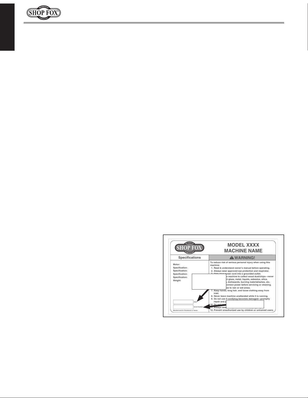
Alternatively, you can call our Technical Support
for help. Before calling, make sure you write
down the
from the machine ID label (see below). Also, if
available, have a copy of your original purchase
receipt on hand. This information is required for
all Tech Support calls.
MODEL XXXX
MACHINE NAME
Motor:
Specification:
Specification:
Specification:
Specification:
Weight:
Specifications
To reduce risk of serious personal injury when using this
machine:
1. Read & understand owner’s manual before operating.
2. Always wear approved eye protection and respirator.
3. Only plug power cord into a grounded outlet.
4. Only use this machine to collect wood dust/chips—never
use to collect glass, metal, liquids, asbestos, silica,
animal parts, biohazards, burning material/ashes, etc.
5. Always disconnect power before servicing or cleaning.
6. Do not expose to rain or wet areas.
7. Keep hands, long hair, and loose clothing away from
inlet.
8. Never leave machine unattended while it is running.
9. Do not use if cord/plug becomes damaged—promptly
repair and protect cord from future damage.
10. Do not use without dust bag or filters in place.
11. Always wear a respirator when emptying bags.
12. Prevent unauthorized use by children or untrained users.
Date
Serial Number
Manufactured for Woodstock in Taiwan
WARNING!
We are committed to customer satisfaction. If
you have any questions or need help, use the
information below to contact us.
IMPORTANT: Before contacting, please get the
original purchase receipt, serial number, and
manufacture date of your machine. This information is required for all Technical Support
calls and it will help us help you faster.
We want your feedback on this manual. What did
you like about it? Where could it be improved?
Please take a few minutes to give us feedback.
Email: manuals@woodstockint.com
Model W1823 (Mfd. Since 03/16)
INTRODUCTION
Contact Info
Woodstock International Technical Support
Phone: (360) 734-3482
Email: techsupport@woodstockint.com
Technical Documentation Manager
P.O. Box 2309
Bellingham, WA 98227
Manual Accuracy
made every effort to be exact with
also means that sometimes the
.
,
e post current
manual updates for free
woodstockint.com.
Manufacture Date and Serial Number
Manufacture
Date
Serial Number
-2-
Page 5
Model W1823 (Mfd. Since 03/16)
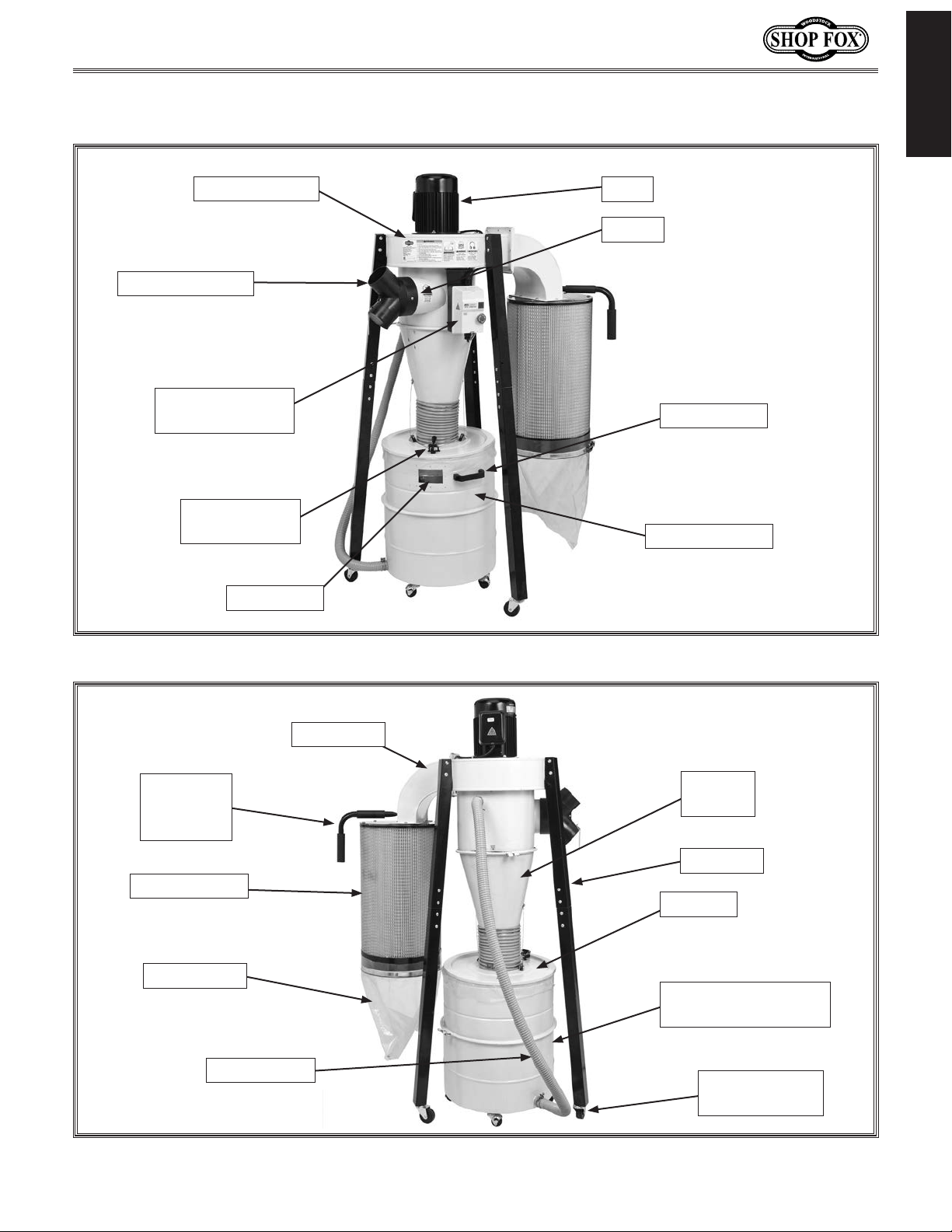
Controls and Features
INTRODUCTION
Blower Housing
6" x 4" Y-Adapter
Remote Magnetic
Switch
Quick Release
Lever
Fill Window
Motor
6" Inlet
Drum Handle
Drum Extension
Filter
Cleaning
Handle
Canister Filter
Canister Bag
Vacuum Hose
Figure 1. Right side view.
Outlet Port
Cyclone
Funnel
Stand Leg
Drum Lid
Dust Collection Drum
with Collection Bag
Locking Swivel
Caster
Figure 2. Left side view.
-3-
Page 6

INTRODUCTION
Model W1823 (Mfd. Since 03/16)
MODEL W1823
11/2 HP PORTABLE CYCLONE
Product Dimensions
Weight.......................................................................................................... 140 lbs.
Width (side‐to‐side) x Depth (front‐to‐back) x Height................................... 37 x 32 x 70‐1/2 in.
Footprint (Length x Width).............................................................................. 37 x 32 in.
Shipping Dimensions
Carton #1
Type............................................................................................. Cardboard Box
Content................................................................................................. Machine
Weight................................................................................................... 147 lbs.
Length x Width x Height..................................................................... 41 x 22 x 22 in.
Carton #2
Type............................................................................................. Cardboard Box
Content......................................................................................... Canister Filter
Weight.................................................................................................... 19 lbs.
Length x Width x Height..................................................................... 17 x 17 x 17 in.
Electrical
Power Requirement.......................................................... 120V or 240V, Single‐Phase, 60 Hz
Prewired Voltage................................................................................................. 120V
Full‐Load Current Rating.............................................................. 15A at 120V, 7.5A at 240V
Minimum Circuit Size................................................................... 20A at 120V, 15A at 240V
Connection Type......................................................................................... Cord & Plug
Power Cord Included.............................................................................................. Yes
Power Cord Length............................................................................................... 7 ft.
Power Cord Gauge............................................................................................ 14 AWG
Plug Included....................................................................................................... Yes
Included Plug Type.................................................................................... 5‐15 for 120V
Recommended Plug Type............................................................................. 6‐15 for 240V
Switch Type....................................................... Control Panel w/Magnetic Switch Protection
Voltage Conversion Kit......................................................................... X1823084 for 240V
Motors
Main
Type.............................................................. TEFC Capacitor‐Start Induction (Class E)
Horsepower.............................................................................................. 1.5 HP
Phase.............................................................................................. Single‐Phase
Amps................................................................................................... 15A/7.5A
Speed.................................................................................................. 3450 RPM
Power Transfer ................................................................................... Direct Drive
Bearings................................................................. Sealed & Permanently Lubricated
-4-
Page 7

Model W1823 (Mfd. Since 03/16)
Main Specifications
Operation
Dust Collector Type.................................................................... Two‐Stage (Cyclone)
Approved Dust Types.................................................................................... Wood
Filter Type.................................................................................. Pleated Cartridge
Airflow Performance................................................................................. 806 CFM
Max Static Pressure (at 0 CFM)...................................................................... 10.4 in.
Main Inlet Size............................................................................................. 6 in.
Inlet Adapter Included..................................................................................... Yes
Number of Adapter Inlets.................................................................................... 2
Adapter Inlet Size......................................................................................... 4 in.
Machine Collection Capacity At One Time................................................................. 2
Maximum Material Collection Capacity......................................................... 4.3 cu. ft.
Filtration Rating................................................................................ 0.2 – 2 Micron
Bag Information
Number of Lower Bags........................................................................................ 1
Lower Bag Diameter................................................................................ 14‐5/8 in.
Lower Bag Length................................................................................... 11‐7/8 in.
INTRODUCTION
Canister Information
Number of Canister Filters................................................................................... 1
Canister Filter Diameter........................................................................... 14‐1/2 in.
Canister Filter Length.............................................................................. 23‐5/8 in.
Collection Drum Size............................................................................... 20 Gallons
Impeller Information
Impeller Type....................................................................................... High Curve
Impeller Size......................................................................................... 12‐3/4 in.
Impeller Blade Thickness.............................................................................. 1/8 in.
Construction
Lower Bag......................................................................................... Clear Plastic
Canister................................................................................ Spun Bond Polyyester
Frame....................................................................................................... Steel
Caster....................................................................................................... Steel
Impeller.............................................................................................. Aluminum
Paint Type/Finish............................................................................. Powder Coated
Collection Drum........................................................................................... Steel
Other
Country of Origin ............................................................................................. Taiwan
Warranty ....................................................................................................... 2 Years
Approximate Assembly & Setup Time ................................................................. 30 Minutes
Serial Number Location ............................................................. ID Label on Blower Housing
Sound Rating .................................................................................................... 82 dB
ISO 9001 Factory .................................................................................................. Yes
Certified by a Nationally Recognized Testing Laboratory (NRTL) .......................................... No
-5-
Page 8

Model W1823 (Mfd. Since 03/16)
SAFETY
OWNER’S MANUAL.
TRAINED OPERATORS ONLY.
DANGEROUS ENVIRONMENTS.
MENTAL ALERTNESS REQUIRED.
electrical components or improperly grounded
manual uses a series of symbols and signal words intended to convey the level of importance of the
safety messages. The progression of symbols is described below. Remember that safety messages by
SAFETY
For Your Own Safety,
Read Manual Before Operating Machine
The purpose of safety symbols is to attract your attention to possible hazardous conditions. This
SAFETY
themselves do not eliminate danger and are not a substitute for proper accident prevention measures—this responsibility is ultimately up to the operator!
NOTICE
Standard Machinery Safety Instructions
Standard Machinery Safety Instructions
Indicates an imminently hazardous situation which, if not avoided,
WILL result in death or serious injury.
Indicates a potentially hazardous situation which, if not avoided,
COULD result in death or serious injury.
Indicates a potentially hazardous situation which, if not avoided,
MAY result in minor or moderate injury.
This symbol is used to alert the user to useful information about
proper operation of the equipment or a situation that may cause
damage to the machinery.
Read and understand this
owner’s manual BEFORE using machine.
have a higher risk of being hurt or killed. Only
allow trained/supervised people to use this
machine. When machine is not being used,
disconnect power, remove switch keys, or
lock-out machine to prevent unauthorized
use—especially around children. Make
workshop kid proof!
machinery in areas that are wet, cluttered,
or have poor lighting. Operating machinery
in these areas greatly increases the risk of
accidents and injury.
alertness is required for safe operation of
machinery. Never operate under the influence
of drugs or alcohol, when tired, or when
distracted.
Untrained operators
Do not use
Full mental
ELECTRICAL EQUIPMENT INJURY RISKS. You can
be shocked, burned, or killed by touching live
machinery. To reduce this risk, only allow an
electrician or qualified service personnel to
do electrical installation or repair work, and
always disconnect power before accessing or
exposing electrical equipment.
DISCONNECT POWER FIRST. Always disconnect
machine from power supply BEFORE making
adjustments, changing tooling, or servicing
machine. This eliminates the risk of injury
from unintended startup or contact with live
electrical components.
EYE PROTECTION. Always wear ANSI-approved
safety glasses or a face shield when operating
or observing machinery to reduce the risk of
eye injury or blindness from flying particles.
Everyday eyeglasses are not approved safety
glasses.
-6-
Page 9

Model W1823 (Mfd. Since 03/16)
WEARING PROPER APPAREL. Do not wear
HAZARDOUS
HEARING PROTECTION.
REMOVE ADJUSTING TOOLS.
INTENDED USAGE.
AWKWARD POSITIONS.
CHILDREN & BYSTANDERS.
GUARDS & COVERS.
FORCING MACHINERY. Do not force machine. It
will do the job safer and better at the rate for
loss of control. Before starting, verify machine
malfunction, leading to serious personal injury
from heated surfaces, high traffic areas, harsh
clothing, apparel, or jewelry that can become
entangled in moving parts. Always tie back
or cover long hair. Wear non-slip footwear to
avoid accidental slips, which could cause loss
of workpiece control.
DUST. Dust created while using
machinery may cause cancer, birth defects,
or long-term respiratory damage. Be aware of
dust hazards associated with each workpiece
material, and always wear a NIOSH-approved
respirator to reduce your risk.
Always wear hearing
protection when operating or observing
loud machinery. Extended exposure to this
noise without hearing protection can cause
permanent hearing loss.
machinery can become dangerous projectiles
upon startup. Never leave chuck keys,
wrenches, or any other tools on machine.
Always verify removal before starting!
intended purpose—never make modifications
without prior approval from Woodstock
International. Modifying machine or using
it differently than intended will void the
warranty and may result in malfunction or
mechanical failure that leads to serious
personal injury or death!
balance at all times when operating machine.
Do not overreach! Avoid awkward hand
positions that make workpiece control difficult
or increase the risk of accidental injury.
bystanders at a safe distance from the work
area. Stop using machine if they become a
distraction.
Only use machine for its
Tools left on
Keep proper footing and
Keep children and
which it was designed.
NEVER STAND ON MACHINE. Serious injury may
occur if machine is tipped or if the cutting
tool is unintentionally contacted.
STABLE MACHINE. Unexpected movement during
operation greatly increases risk of injury or
is stable and mobile base (if used) is locked.
USE RECOMMENDED ACCESSORIES. Consult
this owner’s manual or the manufacturer for
recommended accessories. Using improper
accessories will increase risk of serious injury.
UNATTENDED OPERATION. To reduce the risk
of accidental injury, turn machine OFF and
ensure all moving parts completely stop
before walking away. Never leave machine
running while unattended.
MAINTAIN WITH CARE. Follow all maintenance
instructions and lubrication schedules to
keep machine in good working condition. A
machine that is improperly maintained could
or death.
CHECK DAMAGED PARTS. Regularly inspect
machine for any condition that may affect
safe operation. Immediately repair or replace
damaged or mis-adjusted parts before
operating machine.
MAINTAIN POWER CORDS. When disconnecting
cord-connected machines from power, grab
and pull the plug—NOT the cord. Pulling the
cord may damage the wires inside, resulting
in a short. Do not handle cord/plug with wet
hands. Avoid cord damage by keeping it away
chemicals, and wet/damp locations.
SAFETY
accidental contact with moving parts or flying
debris—make sure they are properly installed,
undamaged, and working correctly.
Guards and covers reduce
EXPERIENCING DIFFICULTIES. If at any time
you experience difficulties performing the
intended operation, stop using the machine!
-7-
Contact Technical Support at (360) 734-3482.
Page 10

Model W1823 (Mfd. Since 03/16)
INTENDED USE. This dust collector is only
OPERATING LOCATION.
DISCONNECTING POWER SUPPLY.
IMPELLER HAZARDS.
HAZARDOUS
DUST ALLERGIES.
there is a possibility of an allergic reaction.
EMPTYING DUST. When emptying dust from
DO NOT operate the dust collector
in areas where explosion risks are high. Areas
areas near pilot lights, open flames, or other
reduce this risk, thoroughly ground all plastic
Regularly check/empty the
Additional Safety for Dust Collectors
intended for collecting wood dust and chips
from woodworking machines. DO NOT use
this dust collector to collect metal, dirt,
pebbles, drywall, asbestos, lead paint,
SAFETY
silica, liquids, aerosols, or any flammable,
combustible, or hazardous materials.
To reduce respiratory
exposure to fine dust, locate permanently
installed dust collectors away from the
working area, or in another room that is
equipped with a smoke detector. DO NOT
operate the dust collector in rainy or wet
locations—exposure to water may create a
shock hazard or decrease machine life.
switch OFF, disconnect the dust collector
from the power supply, and allow the
impeller to completely stop before
leaving the machine unattended or doing
any service, cleaning, maintenance, or
adjustments.
DO NOT place your hair,
loose clothing, hands, or tools near the open
inlet during operation for any reason. Only
operate machine with ducting attached to
inlet. The powerful suction could easily
cause accidental contact with the impeller,
which will cause serious personal injury or
damage to the machine. Always keep small
animals and children away from open dust
collection inlets.
Turn the
the collection container, wear a respirator
and safety glasses. Empty dust away from
ignition sources and into an approved
container.
FIRE SUPPRESSION. Only operate the dust
collector in locations that contain a
fire suppression system or have a fire
extinguisher nearby.
SUSPENDED DUST PARTICLES AND IGNITION
SOURCES.
of high risk include, but are not limited to,
ignition sources.
AVOIDING SPARKS. DO NOT allow steel or rocks
to strike the impeller—this may produce
sparks. Sparks can smolder in wood dust
for a long time before a fire is detected. If
you accidentally cut into wood containing
tramp metal (nails, staples, spikes, etc.),
immediately turn OFF the dust collector,
disconnect it from power, and wait for the
impeller to stop—then empty the collection
container into an approved airtight metal
container.
STATIC ELECTRICITY. High amounts of static
electricity are generated when plastic
ducting is used for dust collection lines.
Although rare, sparks caused by static
electricity can cause explosions or fire. To
DUST—WEAR RESPIRATOR. Fine
dust that is too small to be caught in the
filter will be blown into the ambient air
during operation. Always wear a NIOSHapproved respirator during operation and
for a short time after to reduce your risk of
permanent respiratory damage.
Dust from certain woods may
cause an allergic reaction in people and
animals. Make sure you know what type of
wood dust you will be exposed to in case
ducting used in the dust collection system.
REGULAR CLEANING.
collection bags or drum to avoid buildup of
-8-
fine dust that can increase the risk of fire.
Make sure to regularly clean the surrounding
area where the machine is operated—
excessive dust buildup on overhead lights,
heaters, electrical panels, or other heat
sources will increase the risk of fire.
Page 11
Model W1823 (Mfd. Since 03/16)
This machine must be connected to the correct size and
type of power supply circuit, or fire or electrical damage
may occur. Read through this section to determine if an
adequate power supply circuit is available. If a correct
circuit is not available, a qualified electrician MUST install
one before you can connect the machine to power.
A power supply circuit includes all electrical equipment
between the breaker box or fuse panel in the building
and the machine. The power supply circuit used for
this machine must be sized to safely handle the fullload current drawn from the machine for an extended
period of time. (If this machine is connected to a circuit
protected by fuses, use a time delay fuse marked D.)
This machine is prewired to operate on a 120V power
supply circuit that has a verified ground and meets the
following requirements:
This machine can be converted to operate on a 240V
power supply (details about voltage conversion can be
found later in this manual). The 240V power supply circuit
must have a verified ground and meet the requirements
that follow:
The full-load current rating is the amperage a machine
draws at 100% of the rated output power. On machines
with multiple motors, this is the amperage drawn by the
largest motor or sum of all motors and electrical devices
that might operate at one time during normal operations.
or machine damage. To reduce this risk,
a dedicated circuit—
where only one machine will be running
multiple machines will be running at the
ELECTRICAL
Circuit Requirements
The machine must be properly set up
before it is safe to operate. DO NOT
connect this machine to the power
source until instructed to do later in
this manual.
ELECTRICAL
Full-Load Current Rating
Full-Load Current Rating at 120V .................. 15 Amps
Full-Load Current Rating at 240V ................. 7.5 A m p s
Circuit Requirements for 120V (Prewired)
Circuit Type ...................... 120V, 60 Hz, Single-Phase
Circuit Size ............................................. 20 Amps
Plug/Receptacle .................................... NEMA 5-15
Circuit Requirements for 240V
Circuit Type ......................240V, 60 Hz, Single-Phase
Circuit Size ............................................. 15 Amps
Plug/Receptacle .................................... NEMA 6-15
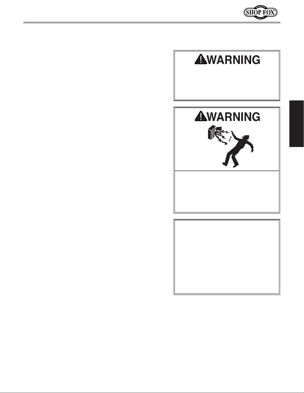
Incorrectly wiring or grounding this
machine can cause electrocution, fire,
only an electrician or qualified service
personnel should do any required
electrical work on this machine.
NOTICE
The circuit requirements listed in this
manual apply to
at a time. If this machine will be
connected to a shared circuit where
same time, consult with an electrician
to ensure that the circuit is properly
sized for safe operation.
-9-
Page 12
Grounding Requirements
This machine MUST be grounded. In the event of certain
types of
a path of least resistance for electric current
order
Improper connection of the equipment-grounding
will
increase
insulation
grounding
cord or plug is necessary, do not connect the equipmentgrounding
Check with a qualified electrician or service personnel
if
or if
properly grounded.
plug is damaged or worn, disconnect it from power, and
immediately replace it with a new one.
This machine is equipped with a power cord that has an
equipment-grounding
The plug
receptacle
(
accordance with local codes and ordinances.
A NEMA 6-15 plug has a grounding prong that must be
attached to the equipment-grounding wire inside the
included power cord.
into a matching
installed and grounded in accordance with all local codes
and ordinances.
We do not recommend using an extension cord with
Any extension cord used with this machine must contain a
plug and receptacle, and
meet the following requirements:
Model W1823 (Mfd. Since 03/16)
malfunctions or breakdowns, grounding provides
to reduce the risk of electric shock.
the risk of electric shock. The wire with green
(with/without yellow stripes) is the equipment-
wire. If repair or replacement of the power
wire to a live (current carrying) terminal.
you do not understand these grounding requirements,
ELECTRICAL
you are in doubt about whether the tool is
If you ever notice that a cord or
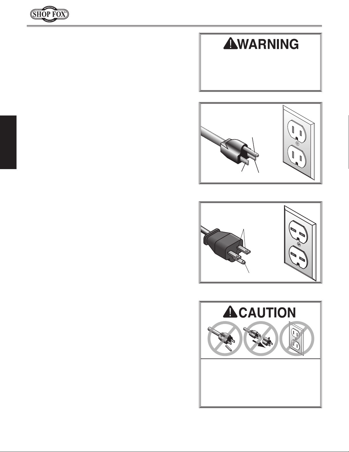
For 120V Connection (Prewired)
wire and NE M A 5-15 grounding plug.
must only be inserted into a matching
see Figure) that is properly installed and grounded in
to travel—in
wire
The machine must be properly set up
before it is safe to operate. DO NOT
connect this machine to the power
source until instructed to do later in
this manual.
120V
5-15 PLUG
Figure 3. NEMA 5-15 plug & receptacle.
240V
Current Carrying Prongs
GROUNDED
5-15 RECEPTACLE
Grounding Prong
Neutral Hot
GROUNDED
6-15 RECEPTACLE
For 240V Connection (Must be Rewired)
The plug must only be inserted
receptacle (see Figure) that is properly
this machine. Extension cords cause voltage drop, which
may damage electrical components and shorten motor
life. Voltage drop increases with longer extension cords
and smaller gauge sizes (higher gauge numbers indicate
smaller sizes).
ground wire
Minimum Gauge Size ................................. 14 AWG
Maximum Length (Shorter is Better) ................50 ft.
Extension Cords
, match the required
6-15 PLUG
Grounding Prong
Figure 4. NEMA 6-15 plug & receptacle.
DO NOT modify the provided plug or
use an adapter if the plug will not
fit the receptacle. Instead, have an
electrician install the proper receptacle
on a power supply circuit that meets
the requirements for this machine.
-10-
Page 13
Model W1823 (Mfd. Since 03/16)
SETUP
Unpacking
This machine has been carefully packaged for safe
transportation. If you notice the machine has been
damaged during shipping, please contact your authorized
Shop Fox dealer immediately.
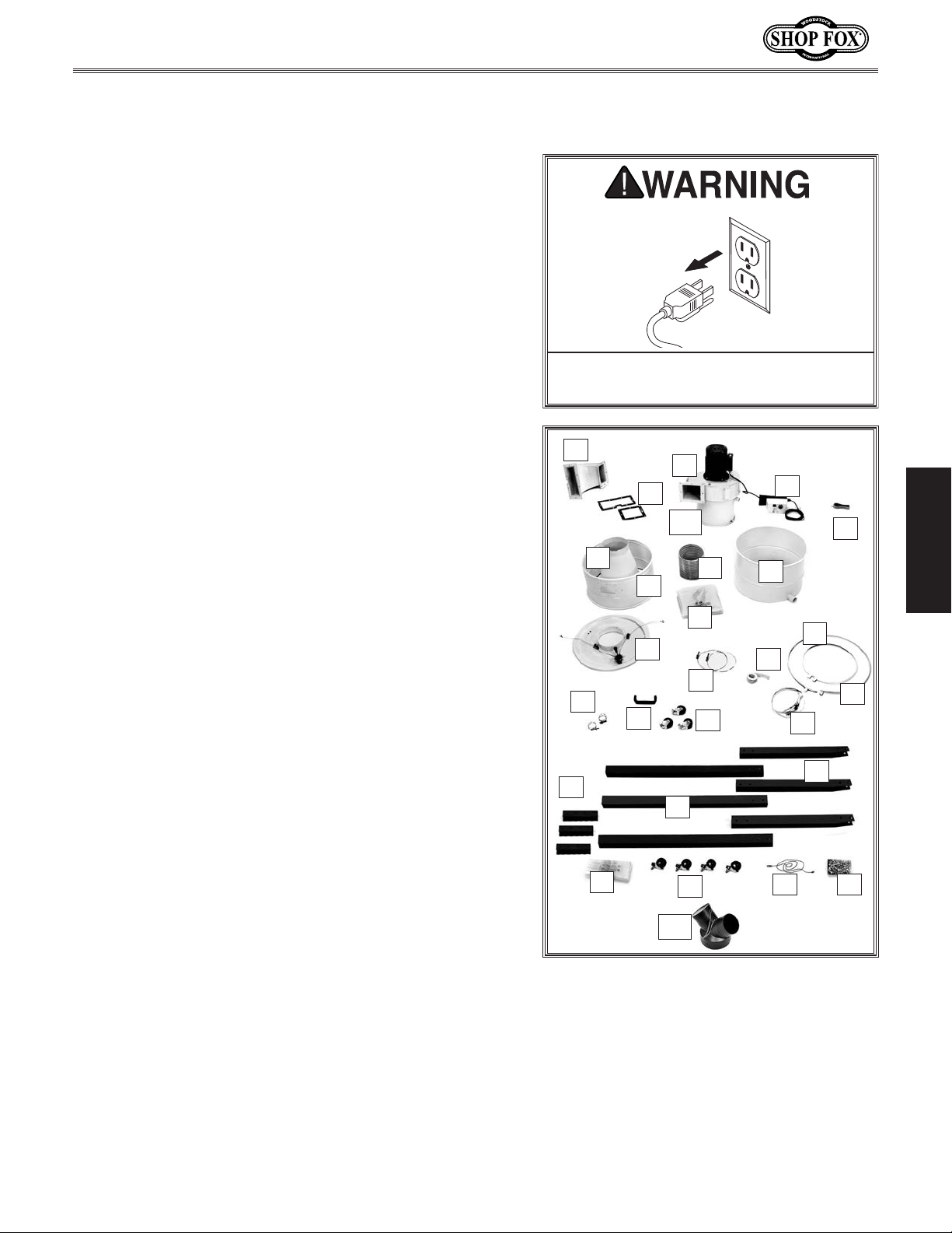
Inventory
The following is a description of the main components
shipped with the Model W1823. Lay the components out
to inventory them.
Note: If you can't find an item on this list, check the
mounting location on the machine or examine the
packaging materials carefully. Occasionally we pre-install
certain components for safer shipping.
Main Inventory (Figure 5) Qty
A. Outlet Port..................................................1
B. Outlet Port Gasket Set ...................................1
C. Blower Assembly ...........................................1
D. Magnetic Switch Assembly for 120V ....................1
E. RF Remote Control ........................................1
F. Collection Drum ...........................................1
G. Cyclone Funnel .............................................1
H. Collection Drum Extension ...............................1
I. Dust Hose 7" Diameter ....................................1
J. Collection Drum Bag ......................................1
K. Collection Drum Lid w/Lift System .....................1
L. Hose Clamps 7" Diameter ................................2
M. Foam Tape ..................................................1
N. Collection Drum Clamp ...................................1
O. Barrel Clamp ...............................................1
P. Hose Clamps 1
Q. Stand Leg Swivel Casters ................................3
R. Quick-Release Canister Bag Clamp .....................1
S. Collection Drum Handle ..................................1
T. Upper Legs ..................................................3
U. Lower Legs ..................................................3
V. Leg Connectors ............................................3
W. Canister Bag ................................................1
X. Collection Drum Swivel Casters .........................4
Y. Ground Wire ................................................1
Z. Hardware and Tool Bag (see Figure 6).................1
AA. Y-Adapter 6" x 4" x 4" w/Cap ............................1
AB. Intake Barrel ...............................................1
3
⁄4" Diameter .............................2
Keep machine disconnected from
power until instructed otherwise.
A
C
B
AB
G
H
J
K
L
P
S
V
W
Figure 5. Main inventory.
Q
U
X
AA
I
D
E
F
N
M
O
R
T
Y Z
SETUP
-11-
Page 14
Model W1823 (Mfd. Since 03/16)
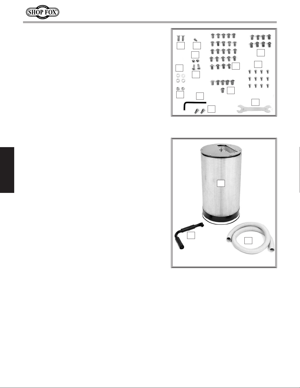
Hardware and Tool Bag Inventory (Figure 6) Qty
1
A. Hex Bolts
B. Flat Washers
C. Lock Nuts
D. Phillips Head Screw 10-24 x
E. Acorn Nuts
F. Phillips Head Screws
G. Button Head Cap Screws
H. Button Head Cap Screws
⁄4"-20 x 3⁄4" (Lift Cable) .....................2
1
⁄4" (Lift Cable) ............................2
1
⁄4"-20 (Lift Cable) ............................2
1
⁄4"-20 (Handle) .............................2
1
⁄4"-20 x 5⁄8" (Handle) ...........2
3
⁄8" (Y-Adapter) ..........1
5
⁄16"-18 x 1⁄2" (Legs) ...... 36
5
⁄16"-18 x 3⁄4"
(Outlet Port to Canister) .................................6
5
I. Button Head Cap Screws
⁄16"-18 x 1⁄2"
(Outlet Port to Blower Housing) ........................8
J. Hex Wrench 6mm ..........................................1
K. Combo Wrench 10 x 12mm ...............................1
5
L. Flange Screws
M. Phillips Head Screws 10-24 x
⁄16"-18 x 1⁄2" (Ground Wire) ...........2
3
⁄8" (Intake Barrel) ... 12
Canister Inventory (Figure 7) Qty
A. Filter Canister w/Cleaning Assembly ...................1
SETUP
B. Filter Cleaning Handle ....................................1
C. Vacuum Hose 1
1
⁄2" x 68" ..................................1
A
D
E
B
G
F
H
C
J
L
Figure 6. Hardware and tool bag
inventory.
A
I
M
K
-12-
B
C
Figure 7. Canister inventory.
Page 15

Model W1823 (Mfd. Since 03/16)
Weight Load
Refer to the
weight of your machine. Make sure that the
surface upon which the machine is placed will
bear the weight of the machine, additional
equipment that may be installed on the
machine, and the heaviest workpiece that will
be used. Additionally, consider the weight of
the operator and any dynamic loading that may
occur when operating the machine.
Space Allocation
Consider the largest size of workpiece that
will be processed through this machine and
provide enough space around the machine
for adequate operator material handling or
the installation of auxiliary equipment. With
permanent installations, leave enough space
around the machine to open or remove doors/
covers as required by the maintenance and
service described in this manual.
required space allocation.
Physical Environment
The physical environment where your machine is
operated is important for safe operation and the
ambient temperature range exceeds 41°–104°F;
(non-condensing); or the environment is subject
source. Make sure all power cords are protected
chemicals, or other hazards. Make sure to leave
Machine Placement
Machine Specifications for the
longevity of its components. For best results,
operate this machine in a dry environment
that is free from excessive moisture, hazardous
chemicals, airborne abrasives, or extreme
conditions. Extreme conditions for this type
of machinery are generally those where the
the relative humidity range exceeds 20–95%
to vibration, shocks, or bumps.
Electrical Installation
Place this machine near an existing power
See below for
Children or untrained people
may be seriously injured by this
machine. Only install in an access
restricted location.
Suction
Ports
Power
Connection
from traffic, material handling, moisture,
access to a means of disconnecting the power
source or engaging a lockout/tagout device.
Lighting
Lighting around the machine must be adequate
enough that operations can be performed
safely. Shadows, glare, or strobe effects that
may distract or impede the operator must be
eliminated.
34"
SETUP
46"
Figure 8. Model W1823 working clearances.
-13-
Page 16

Assembly
Before beginning assembly, refer to the inventory list and
group all fasteners with their intended components. Also,
refer the parts breakdown, provided at the back of this
manual, for additional assistance. Doing this will make the
assembly process easier.
Model W1823 (Mfd. Since 03/16)
Leg Support
Boss
Blower
Housing
When assembling this machine, tighten fasteners using
hand tools only. Avoid using air or electric impact tools
because fasteners can easily be over-tightened, causing
them to dig into the paint, strip threads, and overcompress gaskets—causing flanges to deform and leak.
Using silicone sealant at connection points is optional.
To assemble the dust collector, do these steps:
1. With the help of another person, place the blower
housing on its side carefully as not to scratch
the paint. Attach the intake barrel to the blower
3
housing, using (12) 10-24 x
⁄8" Phillips head screws.
2. Fasten the three upper legs to the leg support bosses
SETUP
on the blower housing with (12)
5
⁄16"-18 x 1⁄2" button
head cap screws, as shown in Figure 9.
3. Thread the caster wheels into the lower legs and
tighten.
4. Insert and fasten the leg connectors in the lower
5
legs using (12)
⁄16"-18 x 1⁄2" button head cap screws,
as shown in Figure 10.
Upper Leg
Button
Head
Cap
Screw
Figure 9. Upper leg installed on blower
housing leg support boss.
Figure 10. Lower leg connector and swivel
caster installation.
5. Insert the leg connectors into the upper legs, as
shown in Figure 11, and secure together with (12)
5
⁄16"-18 x 1⁄2" button head cap screws.
Note: You will notice that the bolt pattern in the
upper legs and the leg connectors (Figure 11) is
off–center to ensure that the lower legs can only be
installed in the correct direction.
-14-
Leg
Connector
Lower LegUpper Leg
Figure 11. Inserting a lower leg into an
upper leg.
Page 17

Model W1823 (Mfd. Since 03/16)
6. Using the square port in the blower housing (see
Figure 12) for access, fasten the magnetic switch
5
bracket on the studs with (2)
5
⁄16"-18 hex nuts.
(2)
⁄16" flat washers and
7. With the help of another person, lift and position the
dust collector upright, then lock the casters so the
unit will not move during the rest of the assembly
process.
8. Have another person hold the cyclone funnel in-
place against the intake barrel, and align the datum
point labels, as shown in Figure 13, then clamp the
cyclone funnel and the intake barrel together using
the barrel clamp. To ensure a tight seal, make sure
the clamp is tight when it overlaps, as shown in
Figure 13.
Magnetic
Switch
Mounting
Bracket
Bolts
Figure 12. Magnetic switch installation.
Overlap
Intake Barrel
SETUP
9. Connect the outlet port and its larger gasket to the
5
filter canister with (6)
⁄16"-18 x 3⁄4" button head cap
screws. Do not overtighten the screws, or the outlet
port flanges will bend and cause the gaskets to leak.
10. Have another person hold the canister filter in place
while you fasten the outlet port and its smaller
5
gasket to the blower housing with (8)
⁄16"-18 x 1⁄2"
button head cap screws, as shown in Figure 14.
11. Reach inside the canister filter and rotate the
cleaning flap so the flat on the filter cleaning rod
faces outward.
12. Place the cleaning handle onto the shaft, align the
flat and set screw, then tighten the set screw (see
Figure 14).
Alignment
Cyclone
Funnel
Figure 13. Cyclone funnel installation.
Outlet Port
Set
Screw
Figure 14. Filter canister installation.
-15-
Page 18

Model W1823 (Mfd. Since 03/16)
13. Fasten one end of the 11⁄2" diameter vacuum hose to
3
the intake barrel using one of the 1
⁄4" hose clamps,
as shown in Figure 15.
14. Fasten the inlet Y-adapter to the intake barrel
5
suction port and secure in place with the
3
⁄8" Phillips head screw, as shown in Figure 16.
⁄16"-18 x
Figure 15. Vacuum tube installed.
SETUP
15. Affix the 1" wide foam tape to the underside of the
drum lid, as shown in Figure 17.
Screw
Figure 16. Inlet Y-adapter installed.
Foam
Tape
Figure 17. Collection drum cover seal and
lift cable clamping location.
-16-
Page 19

Model W1823 (Mfd. Since 03/16)
16. With the cyclone funnel port still open for access to
the hex nuts inside, fasten the ends of the lift cables
to the outside of the cyclone funnel, as shown in
Figure 18, using the pre-installed hex bolts.
17. Slide the 7" hose clamps onto the ports of the
collection drum lid and the cyclone funnel (see
Figure 18).
Tip: You can disassemble the hose clamps for more
clearance to get the clamps positioned over the
hose. To reassemble the clamps, refer to Figure 19.
18. Work the 7" hose onto both ports, position the hose
clamps on the hose, then tighten them.
19. Connect the ground wire between the drum cover
5
and leg with the included (2)
⁄16"-18 x 1⁄2" flange
screws, as shown in Figure 20. This wire prevents
accumulation of static electricity at the collection
drum.
20. Position the lift cable in the wheel grooves.
Lift Cable
End
Figure 18. Collection lid installation.
SETUP
Figure 19. Correct hose clamp assembly.
21. Lower the lid release lever and verify that the lower
1
edge of the lid flange is approximately 25
⁄2" above
the floor, as shown Figure 21 so the dust collection
drum can be rolled under the dust collector without
interference from the lid.
— If the drum hits the lid when it is raised, loosen
the hose and reposition the lid higher. Do not
attempt to adjust the cables.
Flange
Screws
Ground Wire
Ground Screw
Figure 20. Ground wire location.
Release
Lever
-17-
Figure 21. Checking collection lid lift.
Page 20

22. Place the drum extension on top of the collection
drum, and orient the window, vacuum hose port, and
the clamp bolt, as shown in Figure 22.
23. Install and tighten the drum clamp, as shown in
Figure 22.
24. Thread the four swivel casters into the underside of
the drum.
1
25. Fasten the 1
collection drum with the 1
⁄2" diameter vacuum hose onto the
3
⁄4" hose clamp, as shown
Figure 22.
1
26. Place two
⁄4"-20 acorn nuts in the handle, and
fasten the handle to the drum extension with two
1
⁄4"-20 x 5⁄8" Phillips head screws, as shown Figure
23.
Model W1823 (Mfd. Since 03/16)
Drum Clamp
Window
Vacuum Hose
Figure 22. Drum and drum extension
positioning and installation.
SETUP
27. Place the dust collection drum bag in the drum and
roll approximately 2" of the bag over the edge of the
drum.
28. Pull the release lever down to lift the drum cover,
roll the drum under the lid, and push the lever
upward to lower the lid on the drum (see Figure
24).
Note: The lid is not designed to rest on top of the
drum with any real force, nor is it designed to snap
into place to create a seal. Instead, a tight seal is
established by the vacuum created when the dust
collector is in operation.
29. Place the canister bag around the bottom edge of
the canister, and clamp it in place with the quick
release bag clamp, as shown Figure 25.
Congratulations! Assembly is complete.
Acorn Nut
Figure 23. Handle installation.
Lid Raised
Lid Lowered
Figure 24. Drum positioning at front of
machine.
-18-
Figure 25. Canister bag installed.
Page 21

Model W1823 (Mfd. Since 03/16)
Test Run
Once the assembly is complete, test run your machine to
make sure it runs properly.
If, during the test run, you cannot easily locate the source
of an unusual noise or vibration, stop using the machine
immediately, then review the Troubleshooting on Page
34.
If you still cannot remedy a problem, contact our
Technical Support at (360) 734-3482 for assistance.
To test run the machine, do these steps:
1. Make sure you have read the safety instructions at
the beginning of the manual and that the machine is
set up properly.
2. Make sure all tools and objects used during setup are
cleared away from the machine.
To reduce the risk of eye injury and
long-term respiratory damage, always
wear safety glasses and a respirator
while operating this machine.
SETUP
3. Connect the machine to the power source.
4. On the magnetic switch cover, push the OFF button
in, then twist it clockwise so it pops out to verify
that the switch has not disabled the machine.
5. Press the ON/OFF button on the RF remote control
to turn the machine ON.
6. Listen and watch for abnormal noises or actions.
The machine should run smoothly with little or no
vibration or rubbing noises.
— Strange or unusual noises must be corrected
before operating the machine further. Always
disconnect the machine from power before
investigating or correcting potential problems.
7. Press the ON/OFF button on the remote control to
make sure it is working properly and test the OFF
button operation on the magnetic switch. When the
OFF button is pushed-in, the machine should not
start with the remote control or the start button on
the magnetic switch cover. When the OFF button is
popped-out, the machine can be started.
Loose hair and clothing could get
caught in machinery and cause serious
personal injury. Keep loose clothing
rolled up and long hair tied up and
away from machinery.
-19-
Page 22

COLLECTION SYSTEM
System Setup
The Model W1823 is designed to collect dust from one
large machine or two small machines at a time. This can
be accomplished by either connecting it to one machine at
a time or by connecting it to multiple machines and using
blast gates to isolate different dust lines. This machine
also works quite well as a point-of-use dust collector.
Tips for Optimum Performance
• Keep ducts between the dust collector and machines
as short as possible.
• Note that flex hose reduces CFM more than smoothwalled duct.
Model W1823 (Mfd. Since 03/16)
• Keep ducting directional changes to a minimum. The
more curved fittings you use, the more resistance to
flow, resulting in loss of suction.
• Gradual directional changes are more efficient than
sudden directional changes (i.e. use 45° elbows in
place of 90° elbows whenever possible).
• Use smooth-walled duct whenever possible.
• The simpler the system, the more efficient and less
costly it will be.
OPERATIONS
• If the dust collector is attached to a 2" or 2
collection port, open another blast gate to increase
the amount of CFM or airflow to maintain proper
cyclonic action and dust separation.
1
⁄2"
-20-
Page 23

Model W1823 (Mfd. Since 03/16)
Duct Material
You have many choices regarding main line and branch
line duct material. For best results, use metal duct for
the main line and branch lines, then use a short length
of flexible hose to connect each machine to the branch
lines.
Plastic duct is also a popular material for home shops.
However, be aware that there is a fire or explosion hazard
if plastic duct material is used for dust collection without
being grounded against static electrical charge build-up.
This topic will be discussed later in the manual.
Metal Duct
The advantage of metal duct (Figure 26) is its
conductivity, and it does not contribute to static
electrical charge build-up. However, static charges are
still produced when dust particles strike other dust
particles as they move through the duct. Since metal duct
is a conductor, it can be grounded quite easily to dissipate
any static electrical charges.
There are quite a number of options when it comes to
metal duct, but metal duct that is specially manufactured
for dust collection is the best choice. When selecting
your metal duct, choose high quality metal duct with
smooth welded internal seams that will minimize airflow
resistance. This type of duct usually connects to other
ducts or elbows with a simple, self-sealing clamp, is very
quick and easy to assemble, and can be dismantled and
re-installed with no problems. This is especially important
if you ever need to change things around in your shop or
add more tools.
Avoid inferior metal duct that requires you to cut it to
length and snap it together. This type of duct is time
consuming to install because it requires you to seal all
the seams with silicone and screw the components on
the ends with sheet metal screws. Another disadvantage
is the rough internal seams and crimped ends that
unavoidably increase static pressure.
OPERATIONS
Figure 26. Examples of metal pipe and
components.
-21-
Page 24

Flexible Duct
Flexible hose is generally used for short runs, small shops
and at rigid duct-to-tool connections. There are many
different types of flex hose on the market today. These
are manufactured from materials such as polyethylene,
PVC, cloth hose dipped in rubber and even metal,
including steel and aluminum.
The superior choice here is metal flex hose that is
designed to be flexible, yet be as smooth as possible to
reduce static pressure loss.
There are also many kinds of pure plastic flexible hose,
such as non-perforated drainage type hose and dryer vent
hose. Drainage type hose, while being economical, does
not quite have the flexibility required for dust collection.
The inside of the duct is also deeply corrugated and
can increase the static pressure loss by as much as 50%
over smooth wall duct. Dryer vent hose, while being
completely flexible, is non-resistant to abrasion and has
a tendency to collapse in a negative pressure system. We
DO NOT recommend using dryer drainage-type vent hose
in your dust collection system.
Model W1823 (Mfd. Since 03/16)
Figure 27. Example of flexible metal duct.
If using flex-hose, you should choose one of the many
types that are designed specifically for the movement
of solid particles, i.e. dust, grains and plastics. However,
the cost of specifically designed flexible duct can vary
greatly. For example, polyethylene hose is well suited for
the removal of particulate matter, especially sawdust,
since it is durable and completely flexible. Also, it is very
economical and available in a wide variety of diameters
OPERATIONS
and lengths for most applications.
Plastic Duct
The popularity of plastic duct (Figure 28) is due to the
fact that it is an economical and readily available product.
It is also simple to assemble and easily sealed against air
loss. The primary disadvantage of plastic duct for dust
collection is the inherent danger of static electrical buildup.
-22-
Figure 28. Example of plastic duct and
components.
Page 25

Model W1823 (Mfd. Since 03/16)
System Grounding
Since plastic hose is abundant, relatively inexpensive,
easily assembled and air tight, it is a very popular
material for conveying dust from woodworking machines
to the dust collector. We recommend using flexible hose
(flex-hose) to connect the woodworking machine to the
dust collector. However, plastic flex-hose and plastic duct
are an insulator, and dust particles moving against the
walls of the plastic duct create a static electrical build
up. This charge will build until it discharges to a ground.
If a grounding medium is not available to prevent static
electrical build up, the electrical charge will arc to the
nearest grounded source. This electrical discharge may
cause an explosion and subsequent fire inside the system.
To protect against static electrical build up inside a nonconducting duct, a bare copper wire should be placed
inside the duct along its length and grounded to the dust
collector. You must also confirm that the dust collector
is continuously grounded through the electrical circuit to
the electric service panel.
Always guard against static electrical
build up by grounding all dust
collection lines.
If you connect the dust collector to more than one
machine by way of a non-conducting branching duct
system and blast gates, the system must still be
grounded as mentioned above. We recommend inserting
a continuous bare copper ground wire (Figure 29) inside
the entire duct system and attaching the wire to each
grounded woodworking machine and dust collector.
Be sure that you extend the bare copper wire down all
branches of the system. Do not forget to connect the
wires to each other with wire nuts when two branches
meet at a “Y” or “T” connection.
Ensure that the entire system is grounded. If using plastic
blast gates to direct air flow, the grounding wire must
be jumped (Figure 30) around the blast gate without
interruption to the grounding system.
We also recommend wrapping the outside of all plastic
ducts with bare copper wire to ground the outside of the
system against static electrical build up. Wire connections
at Y's and T's should be made with wire nuts.
Attach the bare ground wire to each stationary
woodworking machine and attach the dust collector frame
with a ground screw, as shown in Figure 29. Ensure that
each machine is continuously grounded to the grounding
terminal in your electric service panel.
Internal
Ground
Wire
Flex
Hose
Figure 29. Flex-hose grounded to
Copper
Ground Wire
Figure 30. Ground jumper wire when using
plastic blast gates and metal duct.
External
Ground Wire
Ground Screw
machine.
Plastic
Blast
Gate
Metal Duct
OPERATIONS
-23-
Page 26

OPERATIONS
General Operation
The Model W1823 is designed to be a point-of-source dust
collector system, and is capable of collecting dust from
one large machine or two small machines at a time.
This cyclone dust collector creates a vortex from incoming
air that extracts most dust particles and drops them into
the steel collection drum below, while the remaining fine
dust (see Figure 31) travels past the impeller and into the
canister filter. The filter is made of spun-bond polyester,
which catches 99.9% of particles from 0.2 to 2 microns in
size, and is pleated to provide maximum surface area for
efficient airf low.
The canister filter is equipped with a cleaning mechanism
inside that loosens built-up dust so it falls into the bag
below, which improves airflow for a well-used filter.
Model W1823 (Mfd. Since 03/16)
To reduce your risk of serious injury
or damage to the machine, read this
entire manual BEFORE using machine.
To reduce the risk of eye injury and
long-term respiratory damage, always
wear safety glasses and a respirator
while operating this machine.
OPERATIONS
Wood
Chips
Incoming
Wood
Chips and
Fine Dust
Fine Dust
Filter
Cleaning
Handle
-24-
Figure 31. Model W1823 flow.
Page 27

Model W1823 (Mfd. Since 03/16)
Remote Control
Operation
An RF (radio frequency) remote control receiver (Figure
32) and hand-held controller (Figure 33) allow the dust
collector to be turned ON and OFF from more than
75-feet away or from another room. This range will vary
depending upon the density of materials between the
receiver and the hand-held controller, and the battery
level in the remote.
Note: If you need to have one remote simultaneously
control more than one Model W1823 dust collector, you
can reprogram additional dust collector receivers to
recognize the remote control currently being used. Refer
to Remote Control Reprogramming on Page 29 to do
this.
Receiver
(In Magnetic
Switch Box)
If the motor gets too hot, the thermal overload on the
motor will trip, shutting the dust collector down.
If the machine overload trips during operation, do
these steps:
1. Verify that cooling around the motor is not
obstructed and improve ventilation if restricted.
2. Let the motor and electrical circuit cool for 30
minutes.
3. Press the motor reset button (see Figure 34), then
press the ON button on the remote control (see
Figure 33) to restart the dust collector.
4. If the reset button does not function the first time,
repeat Steps 1–3 as needed until the dust collector
turns ON.
Figure 32. Remote control receiver.
OPERATIONS
On/Off Buttons
Figure 33. RF remote control.
Motor
Reset
Button
-25-
Figure 34. Reset button on motor.
Page 28

Model W1823 (Mfd. Since 03/16)
Cyclone Dust Collector Accessories
The following cyclone dust collector accessories may be available through your local Woodstock
International Inc. Dealer. If you do not have a dealer in your area, these products are also available
through online dealers. Please call or e-mail Woodstock International Inc. Customer Service to get a current listing of dealers at: 1-800-840-8420 or at sales@woodstockint.com.
Blast Gates are available in both black ABS plastic and aluminum.
Plastic blast gates are economically priced, have a textured surface
and an easy sliding gate action. For those customers who prefer
metal, our top quality aluminum blast gates feature a cast aluminum
body with steel gate and locking knob. The following types and models are available:
Black ABS Plastic Blast Gates
W1006 3" Outer Diameter
W1007 4" Outer Diameter
W1008 5" Outer Diameter
W1009 6" Outer Diameter
The Model W1053 Grounding Kit provides everything you need to
ground a dust collection system, including directions for installation.
A large system may need more than one kit, so keep plenty of these
on hand. This safety accessory is essential to any complete dust
collection assortment.
The Model W1055 Dust Collection Accessories Kit #2 provides
the necessary hoses, clamps, hoods and fittings to connect two
OPERATIONS
woodworking machines to a dust collector. Air flow to each machine
is controlled by a blast gate. Kit comes complete with comprehensive
instructions and can be expanded even further using our other dust
collection accessories (list enclosed in each box).
Aluminum Blast Gates
W1141 3" Outer Diameter
W1142 4" Outer Diameter
W1141W1006
Kit includes:
• (2) 4" Blast gates (W1007)
• (2) 4" x 10' Hose (W1031)
• (1) Table saw dust hood (W1004)
• (1) Universal dust hood (W1010)
• (1) 4" Y-fitting (W1015)
• (10) 4" Wire hose clamps (W1317)
• Shipping weight: 15 lbs. 14 oz.
• Package size: 24" x 24" x 12"
Y-Fittings are used to attach branch lines to service more than
one machine. This design provides increased lateral air flow and
efficiency over other types of fittings.
W1014: 3" Outer Diameter
W1015: 4" Outer Diameter
-26-
Page 29

Model W1823 (Mfd. Since 03/16)
MAINTENANCE
General
No maintenance such as bearing lubrication is required
on this machine. But it is important to empty the drum
and clean the filter during use. To catch any potential
problems, make it a habit to inspect your machine
before and after you use it.
Check for the following conditions and repair or
replace when necessary:
• Check loose mounting bolts and ducting.
• Check worn or damaged wires.
• Check system for leaks.
• Check for tears in the filter or bags.
• Look for any other unsafe condition.
Emptying Drum
Empty the collection drum when it is approximately 3/4
full as seen through the viewing window. If the drum
is overfilled, dust will be sucked into the inlet cylinder
and pass through to the filter. Sawdust and wood chips
collected from different machines will require you to
adjust the frequency of inspections.
To empty the sawdust from the drum, use the clamping
lever (see Figure 35) on the drum lid to lift the lid and
roll the drum out for emptying.
To empty the canister bag, use the canister quick release
clamp to remove and dump the bag. The bags may be
reused several times. We do not recommend using plain
garbage bags as the wall thickness is insufficient to
prevent blow-out.
MAKE SURE that your machine is
unplugged during all maintenance
procedures! If this warning is ignored,
serious personal injury may occur.
Filter
Cleaning
Handle
OPERATIONS
Quick Release
Clamping Lever
Canister
Dust Bag
Normal Filter Cleaning
Your cyclone dust collector has a set of paddles inside the
filter for cleaning. This paddle system is controlled by the
filter cleaning handle (see Figure 35). To clean the filter,
simply rotate the handle left and right, so the paddles
ripple against the internal filter pleats and knock off the
caked-on dust. The dust will then fall into the collection
bag below. During heavy sanding operations, the canister
may have to be cleaned this way several times during
the day. Periodically inspect the bag, the quick release
clamp, and the canister filter for evidence of any leakage
or tears. If damage is found, immediately replace as
required. Refer to SERVICE for major filter cleaning.
-27-
Drum
Dust Bag
Viewing Window
Lid Raised Lid Lowered
Figure 35. Maintenance locations.
Inside
Page 30

SERVICE
General
This section covers the most common service adjustments
or procedures that may need to be made during the life
of your machine. If you require additional machine service
not included in this section, please contact Woodstock
International Technical Support at (360) 734-3482 or send
e-mail to: tech-support@shopfox.biz.
Major Filter Cleaning
NOTICE
Using compressed air for cleaning or drying can tear
the filter element. Using soapy water or solvents can
also leave residue behind that attracts and bonds
dust particles to the filter, resulting in a permanently
clogged filter. ONLY use the cleaning handle, a soft
brush, or plain water to clean the inside of the canister filter.
Model W1823 (Mfd. Since 03/16)
MAKE SURE that your machine is
unplugged during all service procedures! If this warning is ignored, serious personal injury may occur.
Filter
Cleaning
Handle
Use the filter cleaning handle for an initial filter cleaning.
Next put on safety goggles and a respirator, and remove
and empty the canister dust collection bag. To reach deep
in the pleat-valleys, you can use a straw brush or stiff
paint brush.
For extremely dirty filters, the filter can be carefully
rinsed out with warm water and allowed to air dry.
However, never leave the filter in the sun to dry or it
could shrink and distort. Washing the filter when the
ambient temperature is below 65 degrees or placing the
wet filter in a closed environment without ventilation to
dry can cause mold to grow between the filter pleats.
If possible, use a fan to assist in the drying process, and
never use compressed air to clean or blow-dry the filter.
SERVICE
Collection
Bag
Figure 36. Canister filter and bag.
-28-
Page 31

Model W1823 (Mfd. Since 03/16)
Remote Control
Reprogramming
Reprogramming the receiver on
this machine is done with the
machine connected to power. As
a result, a hazard for shock, fire,
or machine damage exists. ONLY
a qualified electrician or service
person should do this procedure.
This procedure covers how to reprogram the RF receiver
to accept the new remote control frequency. Use
these instructions if you ever replace either of these
components, or convert the machine to operate on 240V.
This procedure can also be used to control multiple
models of this machine with one remote control.
Receiver
(In Magnetic
Switch Box)
To reprogram the remote control, do these steps:
1. DISCONNECT MACHINE FROM POWER!
2. Install a new battery in the remote control.
3. Remove the magnetic switch cover (Figure 37), and
locate the receiver reset button shown in Figure 38.
4. CONNECT THE MACHINE TO POWER.
5. On the receiver (see Figure 38), use an insulated
wooden or plastic dowel to press and hold the reset
button until a triple beep is heard. The original
remote control code is now erased.
6. Press and hold the reset button for 1-second. The
receiver is ready for the new code.
7. On the remote control, press and hold the "ON"
button until a double beep is heard. The remote
control has sent a new code to the receiver that has
been accepted.
Figure 37. Remote control receiver
location.
RF Receiver
Unit
SERVICE
8. On the receiver, press the reset button for 1-second.
The new activation code is now stored in the
receiver, and the remote control is operational.
9. DISCONNECT THE MACHINE FROM POWER, and
reinstall the magnetic switch cover.
-29-
Reset Button
Figure 38. Remote control receiver.
Page 32

Model W1823 (Mfd. Since 03/16)
SHOCK HAZARD.
QUALIFIED ELECTRICIAN
WIRE CONNECTIONS.
WIRE/COMPONENT DAMAGE
. The motor wiring shown in these
shocked, wait at least this long before working
Electrical Safety Instructions
These pages are current at the time of printing. However, in the spirit of improvement, we may
make changes to the electrical systems of future machines. Study this diagram carefully. If you notice
differences between your machine and these wiring diagrams, call Woodstock International Technical
Support at (360) 734-3482.
connected to a power source is extremely
dangerous. Touching electrified parts will
result in personal injury including but not
limited to severe burns, electrocution,
or death. Disconnect the power from
the machine before servicing electrical
components!
hazards of electricity, only a qualified
electrician should perform wiring tasks on this
machine. If you are not a qualified electrician,
get help from one before attempting any kind
of wiring job.
tight to prevent wires from loosening during
machine operation. Double-check all wires
disconnected or connected during any wiring
task to ensure tight connections.
or components increase the risk of serious
personal injury, fire, or machine damage.
If you notice that any wires or components
are damaged while performing a wiring task,
replace those wires or components before
completing the task.
Working on wiring that is
. Due to the inherent
All connections must be
. Damaged wires
MOTOR WIRING
diagrams is current at the time of printing,
but it may not match your machine. Always
use the wiring diagram inside the motor
junction box.
MODIFICATIONS. Using aftermarket parts or
modifying the wiring beyond what is shown
in the diagram may lead to unpredictable
results, including serious injury or fire.
CAPACITORS/INVERTERS. Some capacitors and
power inverters store an electrical charge for
up to five minutes after being disconnected
from the power source. To avoid being
on these components.
ELECTRICAL REQUIREMENTS. You MUST follow
the electrical requirements at the beginning
of this manual when connecting your machine
to a power source.
EXPERIENCING DIFFICULTIES. If you are
experiencing difficulties understanding the
information included in this section, contact
our Technical Support at (360) 734-3482.
The photos and diagrams
SERVICE
included in this section are
best viewed in color. You
can view these pages in
color at www.shopfox.biz.
BLACK
WHITE
GREEN
RED
WIRING DIAGRAM COLOR KEY
BLUE
BROWN
GRAY
ORANGE
-30-
YELLOW
YELLOW
GREEN
PURPLE
PINK
LIGHT
BLUE
BLUE
WHITE
TURQUOISE
Page 33

Model W1823 (Mfd. Since 03/16)
GND
GND
GND
GND
(Prewired)
Wiring Diagram
Motor Prewired
for 120V
Start
Magnetic switch box
assembly must be
replaced with 240V
model for 240V use.
250VAC
250MFD
Capacitor
A
Thermal
Overload
L1
L1
L1/1 L3/5
L2/3
Contactor
SDE MA-15 110V
Run
50MFD
Capacitor
L2
7
250VAC
L2
ON
Motor Junction Box
Rewired for 240V
Start
250MFD
Capacitor
Rewired for 240V
L2
50/60Hz
7V|0V|120V|0V
Transformer
Thermal
Overload
250VAC
Read
Page 30
STOP
Before
Wiring
Run
50MFD
Capacitor
250VAC
5-15 Plug
T1/2 T3/6
T2/4
Remote Control
Reciever
Circuit Board
SJE-MSR-PCB
120 VAC
Hot
Neutral
Ground
8
B
6
Stop Switch
SERVICE
Ground
G
6-15 Plug
-31-
Rewired
for 240V
Hot
240
VAC
Hot
Page 34

240V Conversion
Thermal
Overload
Start
Capacitor
250MFD
250VAC
Run
Capacitor
50MFD
250VAC
Motor Prewired
for 120V
Motor Junction Box
Rewired for 240V
Thermal
Overload
Thermal
Motor Junction Box
Rewired for 240V
The Model W1823 can be converted for 240V. This
conversion requires re-wiring the motor, installing a
240V plug, a 240V magnetic switch box assembly, and
reprogramming the remote control receiver. Only a
qualified electrician or service personnel should
perform this procedure!
To convert the Model W1823 to 240V, do these steps:
1. DISCONNECT MACHINE FROM POWER!
2. Remove the 120V plug from the power cord,
then install a NEMA 6-15 plug, according to the
instructions included with the plug. If no instructions
were included, use the wiring diagram on Page 31.
3. Open the motor junction box, then remove the wire
nuts indicated in Figure 39.
Model W1823 (Mfd. Since 03/16)
Remove
4. Connect the motor wires as shown in Figure 40 by
twisting them together, then twisting a wire nut over
them. Once snug, wrap the wire nut and the wires it
contains with electrical tape to reduce the likelihood
of the wire nut loosening during use, and reinstall
the junction box cover.
SERVICE
Start
250VAC
250MFD
Capacitor
Run
50MFD
Capacitor
250VAC
Remove
Figure 39. Motor wires at 120V.
Re-connect
Overload
and Tighten
Start
250VAC
250MFD
Capacitor
Run
50MFD
Capacitor
250VAC
Re-connect
and Tighten
Figure 40. Motor wires re-positioned for
240V.
-32-
Page 35

Model W1823 (Mfd. Since 03/16)
Thermal
Overload
GND
Start
Capacitor
250MFD
250VAC
Run
Capacitor
50MFD
250VAC
Stop Switch
Motor Prewired
for 120V
Motor Junction Box
Rewired for 240V
Thermal
Overload
6-15 Plug
(As Recommended)
G
GND
GND
GND
Start
Capacitor
250MFD
250VAC
Run
Capacitor
50MFD
250VAC
5. Loosen the two plastic screws that secure the cover
of the magnetic switch box shown in Figure 41, then
remove the cover.
Loosen
Figure 41. Magnetic switch box.
6. Locate the incoming power and outgoing motor cords
(shown in Figure 42) inside the magnetic switch box.
Carefully note the destination of all of the wires
associated with these two cords, and record their
position so that you can return them to the corresponding positions in the 240V magnetic switch box
assembly later.
7. Loosen all of the terminal screws that have wires
from the power cord or motor cord attached, then
remove the wires.
8. Remove the entire 120V magnetic switch box assem-
bly from the dust collector frame.
9. Install the 240V magnetic switch box assembly
(purchased separately) in place of the 120V switch
removed in Step 8, then re-install power and motor
wires on the 240V switch box assembly in the same
positions that they were in on the 120V switch.
Tighten all terminals.
10. At this point, the new remote control receiver inside
your new magnetic switch must be reprogrammed
so it can communicate with your old hand-held
control. To do this, complete the Remote Control
Reprogramming procedure on Page 29.
Magnetic
Switch
Magnetic switch box
Box
assembly must be
replaced with 240V
Assembly
model for 240V use.
Incoming
Power
Cord
5-15 Plug
(Prewired)
L1
L1/1 L3/57L2/3
SDE MA-15 110V
T1/2 T3/68T2/4
Contactor
Remote Control
Reciever
Circuit Board
SJE-MSR-PCB
120 VAC
Hot
Neutral
Ground
L2
6
L1
A
Figure 42. Magnetic switch.
B
Rewired for 240V
L2
L2
ON
Outgoing
Motor Cord
50/60Hz
7V|0V|120V|0V
Transformer
Ground
Rewired
for 240V
Hot
240
VAC
Hot
SERVICE
11. Close the magnetic switch box cover and secure it
with the two plastic screws.
-33-
Page 36

Model W1823 (Mfd. Since 03/16)
Troubleshooting
This section covers the most common problems and corrections with this type of
machine. WARNING! DO NOT make any adjustments until power is disconnected and
moving parts have come to a complete stop!
PROBLEM POSSIBLE CAUSE CORRECTIVE ACTION
Motor will not start. 1. Stop button is pushed in.
2. Remote control batteries are
dead.
3. Remote control frequency is
incorrect.
4. Power supply fuse or circuit
breaker has tripped.
5. Contactor/transformer at fault.
6. Thermal overload has tripped.
7. Start capacitor is at fault.
8. Remote control or receiver at
fault.
9. Motor is at fault.
Motor runs slower than
normal.
1. Poor electrical connection.
2. Run capacitor at fault.
3. Motor is wired incorrectly.
4. Impeller is loose on the motor
shaft.
1. Rotate stop button clockwise so it pops out and is
reset.
2. Replace batteries.
3. Reprogram the receiver to the remote control
(Page 29).
4. Disconnect power, and inspect circuit for electrical
shorts and repair. Replace circuit breaker if it is old
or has tripped many times.
5. Test/replace contactor or transformer.
6. Allow motor and overload to cool, push overload
button back in. Reduce machine load/improve
motor fan air flow for better cooling.
7. Replace start capacitor.
8. Replace remote control or receiver.
9. Replace motor.
1. Inspect the power supply for loose, corroded, or
overheated electrical connections and repair.
2. Replace run capacitor.
3. Have the power source voltage checked and check
wiring.
4. Replace the motor and impeller as a set if the
motor shaft or the impeller hub is damaged.
Loud, repetitious noise,
squealing, or excessive
vibration coming from dust
colle c to r.
SERVICE
5. Motor is at fault.
1. Dust collector is not on a flat
surface and wobbles.
2. Impeller fan is damaged and
unbalanced.
3. The motor mounting is loose.
4. Motor fan cover is dented, causing
the motor fan to hit the cover
while spinning.
5. Impeller is loose on the motor
shaft.
6. Motor bearings at fault.
5. Replace the motor.
1. Stabilize the dust collector.
2. Unplug dust collector, and inspect the impeller for
dents, bends, loose fins. Replace impeller if any
damage is found.
3. Make sure all fasteners on the dust collector are
tight.
4. Replace motor fan cover.
5. Replace the motor and impeller as a set if the
motor shaft or the impeller hub is damaged.
6. Replace the motor.
-34-
Page 37

Model W1823 (Mfd. Since 03/16)
PROBLEM POSSIBLE CAUSE CORRECTIVE ACTION
Dust collector does not
adequately collect dust or
chips; poor performance.
1. Dust collection drum is full.
2. Filter is dirty, drum is full.
3. Dust collector is undersized for
the task.
4. Ducting is at fault.
5. The dust collector is too far away
from the point of suction, or there
are too many sharp bends in the
ducting.
6. The lumber is wet and wood
chips are not flowing through the
ducting smoothly.
7. There is a leak in the ducting, or a
series of small leaks, or too many
open ports.
8. There are not enough open branch
lines at one time, thereby causing
a velocity drop in the main line.
9. The ducting and ports are
incorrectly sized.
10. The machine overall dust
collection design is inadequate.
11. The dust collector is too small for
the dust collection system.
1. Empty collection drum.
2. Clean filter, empty collection drum.
3. Use the correct size duct collector for the type of
machine.
4. Remove dust line from dust collector inlet and
unblock the restriction in the duct line.
5. Relocate the dust collector closer to the point of
suction, and rework ducting without sharp bends.
Refer to Collection System, beginning on Page 20.
6. Process lumber with less than 20% moisture
content.
7. Rework the ducting to eliminate all leaks. Close
dust ports for lines not being used.
8. Open 1 or 2 more blast gates to different branch
lines to allow the velocity in the main line to
increase.
9. Re-install correctly sized ducts and fittings, contact
machine manufacture for larger port dust collection
shroud. Some machines have poor design for dust
collector use.
10. Use a dust collection nozzle on a stand.
11. Install a larger dust collector to power your dust
collection system.
-35-
SERVICE
Page 38

PARTS
Main
Model W1823 (Mfd. Since 03/16)
1-5
50
51
29
30
56-2
56-1
56-5
220V
Magnetic
Switch
Assembly
84
84-1
1-3
84-2
1-1
1-2
56-4
1-4
56-3
28
49
89
Magnetic
Switch
Assembly
67
69
26
110V
56
57
23
12
13
14
24
54
86
55
60
12
4
61
10
1
48
13
85
18
27
3
86
2
88
19
42
65
66
20
6
7
91
17
62
58
16
9
11
14
21
2
5V2
8
15
59
63
37
34A
38
90
24A
36
34
45
74V2
87
73
72
ON OFF
31
68
32
28
39
31
33
35
52
53
40
41
43
71
46
84-3
56-4
25
22
47
PARTS
-36-
Page 39

Model W1823 (Mfd. Since 03/16)
Main Parts List
REF PART # DESCRIPTION REF PART # DESCRIPTION
1 X1823001 MOTOR 1-1/2HP 120/240V 1PH 41 X1823041 FILTER CLEANING FLAPPER
1-1 X1823001-1 MOTOR FAN COVER 42 X1823042 STEEL WIRE RING
1-2 X1823001-2 MOTOR FAN 43 X1823043 PHLP HD SCR 10-24 X 3/8
1-3 X1823001-3 S CAPACITOR 250M 250V 45 X1823045 PHLP HD SCR M5-.8 X 8
1-4 X1823001-4 MOTOR JUNCTION BOX 46 X1823046 CANISTER BAG CLAMP
1-5 X1823001-5 R CAPACITOR 50M 250V 47 X1823047 CANISTER BAG
2 X1823002 HEX NUT 5/16-18 48 X1823048 HEX BOLT 5/16-18 X 3/4
3 X1823003 MOTOR SPACER 49 X1823049 UPPER STAND LEG
4 X1823004 BLOWER HOUSING 50 X1823050 STAND LEG CONNECTOR
5V2 X1823005V2 IMPELLER 12-3/4" ALUMINUM V2.10.13 51 X1823051 LOWER STAND LEG
6 X1823006 IMPELLER FLAT WASHER 52 X1823052 FILTER CLEANING HANDLE GRIP
7 X1823007 CAP SCREW M6-1 X 15 LH 53 X1823053 TUBE CAP 1"
8 X1823008 INTAKE BARREL 54 X1823054 FLANGE SCREW 5/16-18 X 1/2
9 X1823009 PHLP HD SCR 10-24 X 3/8 55 X1823055 SWITCH MOUNTING BRACKET
10 X1823010 CAP SCREW 10-24 X 3/8 56 X1823056 MAGNETIC SWITCH ASSEMBLY 110V
11 X1823011 BARREL CLAMP 56-1 X1823056-1 CONTACTOR SDE MA-15 110V
12 X1823012 HEX BOLT 1/4-20 X 4 56-2 X1823056-2 TRANSFORMER GDM 0-120V
13 X1823013 FLAT WASHER 1/4 56-3 X1823056-3 THERMAL RELAY YEU SHANG 28A
14 X1823014 HEX NUT 1/4-20 56-4 X1823056-4 STOP BUTTON
15 X1823015 CYCLONE FUNNEL 56-5 X1823056-5 CIRCUIT BOARD 110V
16 X1823016 HOSE CLAMP 7" 57 X1823057 LOCK NUT 10-24
17 X1823017 DUST HOSE 7" 58 X1823058 FLAT WASHER 1/4
18 X1823018 COLLECTION DRUM LID 59 X1823059 HEX BOLT 1/4-20 X 3/4
19 X1823019 PHLP HD SCR 1/4-20 X 5/8 60 X1823060 INLET PORT CAP
20 X1823020 COLLECTION DRUM HANDLE 61 X1823061 PHLP HD SCR 10-24 X 1/2
21 X1823021 ACORN NUT 1/4-20 62 X1823062 STEEL BRAIDED WIRE 1.5MM DIA
22 X1823022 COLLECTION DRUM BAG 63 X1823063 LID CLAMPING HANDLE ASSY
23 X1823023 UPPER COLLECTION DRUM 65 X1823065 CLAMPING HANDLE BRACKET
24A X1823024A COLLECTION DRUM ASSEMBLY 66 X1823066 LOCK NUT 10-24
24 X1823024 LOWER COLLECTION DRUM 67 X1823067 PULLEY ASSEMBLY
25 X1823025 COLLECTION DRUM CASTER 68 X1823068 OUTLET PORT
26 X1823026 INLET Y-PORT 6" X 4" X 4" 69 X1823069 COLLECTION DRUM CLAMP
27 X1823027 PHLP HD SCR 10-24 X 3/8 71 X1823071 CLEANING ROD SUPPORT
28 X1823028 BUTTON HD CAP SCR 5/16-18 X 1/2 72 X1823072 CLEANING ROD BASE
29 X1823029 HEX NUT 10-24 73 X1823073 BUSHING
30 X1823030 STAND CASTER W/BRAKE 3" 74V2 X1823074V2 RF REMOTE CONTROL WITH SF LOGO V2.03.16
31 X1823031 HOSE CLAMP 1-3/4" 84 X1823084 MAGNETIC SWITCH ASSEMBLY 220V
32 X1823032 VACUUM HOSE 1-1/2" 84-1 X1823084-1 CONTACTOR SDE MA-18 220V
33 X1823033 SET SCREW M6-1 X 10 84-2 X1823084-2 TRANSFORMER GDM 0-230V
34A X1823034A CANISTER FILTER ASSEMBLY 84-3 X1823084-3 CIRCUIT BOARD 220V
34 X1823034 CANISTER FILTER 85 X1823085 BUTTON HD CAP SCR 5/16-18 X 1
35 X1823035 FILTER CLEANING HANDLE 86 X1823086 FLAT WASHER 5/16
36 X1823036 OUTLET PORT GASKET 87 X1823087 CANISTER FILTER TOP GASKET
37 X1823037 MOTOR CORD 14AWG 3C 88 X1823088 FOAM TAPE 1" X 64"
38 X1823038 POWER CORD 14AWG 3C 89 X1823089 GROUND WIRE
39 X1823039 FILTER CLEANING ROD 90 X1823090 BUTTON HD CAP SCR 5/16-18 X 3/4
40 X1823040 LOCK NUT 10-24 91 X1823091 LOCK NUT 1/4-20
-37-
PARTS
Page 40

Model W1823 (Mfd. Since 03/16)
Label Placement
Safety labels warn about machine hazards and how to prevent serious personal injury. The owner
of this machine MUST maintain the original location and readability of all labels on this machine.
If any label is removed or becomes unreadable, REPLACE that label before allowing machine to
be operated again. Contact us at (360) 734-3482 or www.shopfoxtools.com to order new labels.
81
83
75
77
76
78
82
79
80
REF PART # DESCRIPTION REF PART # DESCRIPTION
75 X1823075 MACHINE ID LABEL 80 X1823080 MODEL NUMBER LABEL
76 X1823076 READ MANUAL LABEL 81 X1823081 INLET WARNING LABEL
77 X1823077 EYE/LUNG HAZARD LABEL 82 X1823082 SF WHITE TOUCH-UP PAINT
78 X1823078 HEAR HAZARD LABEL 83 X1823083 SF BLACK TOUCH-UP PAINT
79 X1823079 ELECTRICITY LABEL
PARTS
-38-
Page 41

Model W1823 (Mfd. Since 03/16)
Page 42

FOLD ALONG DOTTED LINE
FOLD ALONG DOTTED LINE
Place
Stamp
Here
Woodstock international inc.
p.o. box 2309
bellingham, Wa 98227-2309
TAPE ALONG EDGES--PLEASE DO NOT STAPLE
Page 43

WARRANTY
WARRANTY
Woodstock International, Inc. warrants all Shop Fox machinery to be free of defects from workmanship
and materials for a period of two years from the date of original purchase by the original owner.
This warranty does not apply to defects due directly or indirectly to misuse, abuse, negligence or
accidents, lack of maintenance, or reimbursement of third party expenses incurred.
Woodstock International, Inc. will repair, replace, or arrange for a dealer refund at its expense and
at its option, the Shop Fox machine or machine part, which in proper and intended use has proven to
be defective, provided that the original owner returns the product prepaid to an authorized warranty
or repair facility as designated by our Bellingham, Washington office with proof of their purchase of
the product within two years, and provides Woodstock International, Inc. reasonable opportunity to
verify the alleged defect through inspection. If it is determined there is no defect, or that the defect
resulted from causes not within the scope of Woodstock International Inc.'s warranty, then the original
owner must bear the cost of storing and returning the product.
This is Woodstock International, Inc.’s sole written warranty and any and all warranties that may be
implied by law, including any merchantability or fitness, for any particular purpose, are hereby limited
to the duration of this written warranty. We do not warrant that Shop Fox machinery complies with
the provisions of any law, acts or electrical codes. We do not reimburse for third party repairs. In no
event shall Woodstock International, Inc.’s liability under this limited warranty exceed the purchase
price paid for the product, and any legal actions brought against Woodstock International, Inc. shall be
tried in the State of Washington, County of Whatcom. We shall in no event be liable for death, injuries
to persons or property or for incidental, contingent, special or consequential damages arising from the
use of our products.
Every effort has been made to ensure that all Shop Fox machinery meets high quality and durability
standards. We reserve the right to change specifications at any time because of our commitment to
continuously improve the quality of our products.
Page 44

High Quality Machines and Tools
Woodstock International, Inc. carries thousands of products designed
to meet the needs of today's woodworkers and metalworkers.
Ask your dealer about these fine products:
 Loading...