

Page 1
READ THIS FIRST
177335
Model W1706
***IMPORTANT UPDATE***
Applies to Models Mfd. Since 01/23
and Owner's Manual Revised 04/13
Phone #: (360) 734-3482 • Tech Support: [email protected] • Web: www.woodstockint.com
The following changes were recently made since the owner's manual was printed:
• Fasteners were changed/added to reduce machine vibration.
Aside from the information contained in this update, all other content in the owner's manual is
applicable and MUST be read and understood for your own safety.
IMPORTANT: Keep this update with the owner's manual for future reference. If you have any further
questions, contact our Technical Support.
Revised Parts
2V2
3V2
3V2
18
REF PAR T # DESCRIPTION
2V2 X1706002V2 HEX BOLT 5/8-11 X 3 V2.01.23
3V2 X1706003V2 FLAT WASH ER 16. 5 X 38 X 8MM V2.01.23
18 X1706018 LOCK W ASHER 5/8
COPYRIGHT © JAN UARY, 2023 BY WOODST OCK INTERNATIONAL, INC .
WARN IN G: NO PORTION OF THIS MA NUAL MA Y B E REPRO DU CE D I N ANY SHAPE OR FO RM WI TH OUT
THE WRITTEN APPROVAL OF WOODSTOCK INTERNA TI ON AL, I NC .
PR IN TE D I N TAI WA N#225 81 CS
Page 2
#16083DM
READ THIS FIRST
Model W1706
***IMPORTANT UPDATE***
Applies to Models Mfg. Since 10/13
and Owner's Manual Revised March, 2010
Phone #: (360) 734-3482 • Tech Support: [email protected] • Web: www.shopfox.biz
Introduction
The model W1706 bandsaw comes with 3⁄8"
eccentrics (Part # X1706129A) installed behind
the guide bearings. An additional set of
eccentrics (Part # X1706129) have been included
for easier guide bearing adjustments with
bandsaw blades.
1
The reduced projection of the
provides more space for guide bearing
adjustments with
blade support bearings will not damage the
blade tooth set.
1
⁄8" blades, helping ensure
⁄4" eccentrics
1
⁄4"
1
⁄8"
Installation
1. DISCONNECT MACHINE FROM POWER!
2. Put on heavy leather gloves and open
wheel covers. Remove blade as described
in owner's manual.
3. Remove guide-bearing cap screws and guide
bearings (see Figure 1).
4. Loosen cap screw on guide shaft bracket 1⁄2
turn.
3
5. Remove
bracket, and replace with
6. Retighten cap screw on guide shaft bracket.
7. Re-install guide bearings and guide-bearing
cap screws.
8. Install
manual.
9. Close wheel covers.
10. Adjust upper and lower guide bearings and
support bearings as decribed in owner's
manual.
⁄8" eccentrics from guide shaft
1
⁄8" blade as described in owner's
1
⁄4" eccentrics.
Guide Shaft Bracket
Guide
Bearing
Eccentrics
Cap Screw
Guide-Bearing
Cap Screw
Figure 1. Blade support assembly.
COPYRIGHT © OCTOBER, 2013 BY WOODSTOCK INTERNATIONAL, INC.
WARNING: NO PORTION OF THIS MANUAL MAY BE REPRODUCED IN ANY SHAPE OR FORM WITHOUT
THE WRITTEN APPROVAL OF WOODSTOCK INTERNATIONAL, INC.
Printed in Taiwan
Page 3
MODEL W1706
14" BANDSAW
OWNER'S MANUAL
(FOR MODELS MANUFACTURED SINCE 3/13)
Phone: (360) 734-3482 • Online Technical Support: [email protected]
COPYRIGHT © JUNE, 2004 BY WOODSTOCK INTERNATIONAL, INC., REVISED APRIL, 2013 (TS)
177335
WARNING: NO PORTION OF THIS MANUAL MAY BE REPRODUCED IN ANY SHAPE OR FORM WITHOUT
THE WRITTEN APPROVAL OF WOODSTOCK INTERNATIONAL, INC.
#6167CR Printed in Taiwan
Page 4
This manual provides critical safety instructions on the proper setup,
operation, maintenance, and service of this machine/tool. Save this
document, refer to it often, and use it to instruct other operators.
Failure to read, understand and follow the instructions in this manual
may result in fire or serious personal injury—including amputation,
electrocution, or death.
The owner of this machine/tool is solely responsible for its safe use.
This responsibility includes but is not limited to proper installation in
a safe environment, personnel training and usage authorization,
proper inspection and maintenance, manual availability and comprehension, application of safety devices, cutting/sanding/grinding tool
integrity, and the usage of personal protective equipment.
The manufacturer will not be held liable for injury or property
damage from negligence, improper training, machine modifications or
misuse.
Some dust created by power sanding, sawing, grinding, drilling, and
other construction activities contains chemicals known to the State of
California to cause cancer, birth defects or other reproductive harm.
Some examples of these chemicals are:
• Lead from lead-based paints.
• Crystalline silica from bricks, cement and other masonry products.
• Arsenic and chromium from chemically-treated lumber.
Your risk from these exposures varies, depending on how often you
do this type of work. To reduce your exposure to these chemicals:
Work in a well ventilated area, and work with approved safety equipment, such as those dust masks that are specially designed to filter
out microscopic particles.
Page 5

Contents
INTRODUCTION .....................................2
Woodstock Technical Support
Specifications
SAFETY ...............................................4
Standard Machinery Safety Instructions
Additional Safety for Bandsaws
POWER SUPPLY .....................................7
Circuit Requirements
Grounding Requirements
Extension Cords
SETUP ................................................ 9
Unpacking
Inventory
Machine Placement
Cleaning Machine
Setup Procedures
Assembly
Dust Collection
Blade Tracking
Power Connection
Test Run
Additional Adjustments
Tensioning Blade
Adjusting Positive Stop
Aligning Table
Aligning Miter Gauge Body
Adjusting Fence
Adjusting Blade Support Bearings
Adjusting Blade Guide Bearings
OPERATIONS....................................... 26
General
Operation Overview
Disabling & Locking Switch
Basic Controls
Cutting Overview
Workpiece Inspection
Basic Cutting Tips
Table Tilt
Adjusting Guide Post
Ripping
........................................... 32
..................................... 2
............................ 7
.................................. 8
......................................... 9
.......................................... 9
............................ 10
............................... 10
............................... 11
......................................... 11
................................. 13
.................................. 14
.............................. 15
.......................................... 16
............................... 17
........................ 18
................................... 19
................................ 21
.......................................... 26
........................... 27
................................... 28
............................... 29
.......................... 29
.............................. 30
........................................ 31
.......................... 31
.................. 2
...... 4
................ 6
........................ 8
....................... 16
.................... 20
........... 22
.............. 24
................... 27
Crosscutting
Resawing
Cutting Curves
Stacked Cuts
Blade Speed
Blade Information
Blade Changes
ACCESSORIES ...................................... 40
Bandsaw Accessories
MAINTENANCE .................................... 41
General
Cleaning
Protecting Table
Lubrication
SERVICE ............................................ 42
General
Redressing Rubber Tires
Belt Service
Shimming Table
Blade Lead
Aligning Wheels
Electrical Safety Instructions
Wiring Diagram
Troubleshooting
PARTS .............................................. 53
Cabinet Stand
.............................................. 55
Body
Fence & Miter Gauge
WARRANTY ........................................ 61
..................................... 33
......................................... 34
.................................. 35
.................................... 35
..................................... 36
.............................. 37
.................................. 39
........................... 40
.......................................... 41
......................................... 41
................................ 41
...................................... 41
.......................................... 42
....................... 42
..................................... 43
................................. 45
...................................... 46
................................. 47
................. 50
................................. 51
................................. 52
................................... 53
.......................... 57
SAFETYINTRODUCTION
SET UPELECTRICAL MAINTENANCE
OPERATIONS
SERVICE PARTS
USE THE QUICK GUIDE PAGE LABELS TO SEARCH OUT INFORMATION FAST!
Page 6

Model W1706 (Mfg. Since 3/13)
INTRODUCTION
INTRODUCTION
Woodstock Technical Support
This machine has been specially designed to provide many years of trouble-free service. Close attention
to detail, ruggedly built parts and a rigid quality control program assure safe and reliable operation.
Woodstock International, Inc. is committed to customer satisfaction. Our intent with this manual is to
include the basic information for safety, setup, operation, maintenance, and service of this product.
We stand behind our machines! In the event that questions arise about your machine, please contact
Woodstock International Technical Support at (360) 734-3482 or send e-mail to: tech-support@shopfox.
biz. Our knowledgeable staff will help you troubleshoot problems and process warranty claims.
If you need the latest edition of this manual, you can download it from http://www.shopfox.biz.
If you have comments about this manual, please contact us at:
Woodstock International, Inc.
Attn: Technical Documentation Manager
P.O. Box 2309
Bellingham, WA 98227
Email: [email protected]
Specifications
Motor Size ...............................................
Motor Speed ...................................................................................
Power Transfer ........................................................... Multi-Groove Belt Drive
Max. Cutting Width ............................................................................ 131⁄2''
Max. Cutting Height ............................................................................... 6''
Table Size ............................................................................. 14'' W x 14" D
Footprint ........................................................................... 18'' W x 151⁄2" D
Overall Height.....................................................................................73"
Table Height ....................................................................................... 43"
Table Angles (Maximum) ....................................................... 45°right / 10°left
Blade Speeds .................................................................. 1800 and 3100 FPM
Blade Size Range ........................................................................1⁄8" to 3⁄4"
Blade Length ........................................................................ 921⁄2" to 931⁄2"
Bearings .................................................. Permanently-Lubricated Ball Bearings
Power Control .......................................................Push Button ON/OFF Switch
Net Weight ................................................................................... 242 lbs.
1 HP, 110V/220V, 11/5.5A, Single-Phase
1,720 RPM
-2-
Page 7
Model W1706 (Mfg. Since 3/13)
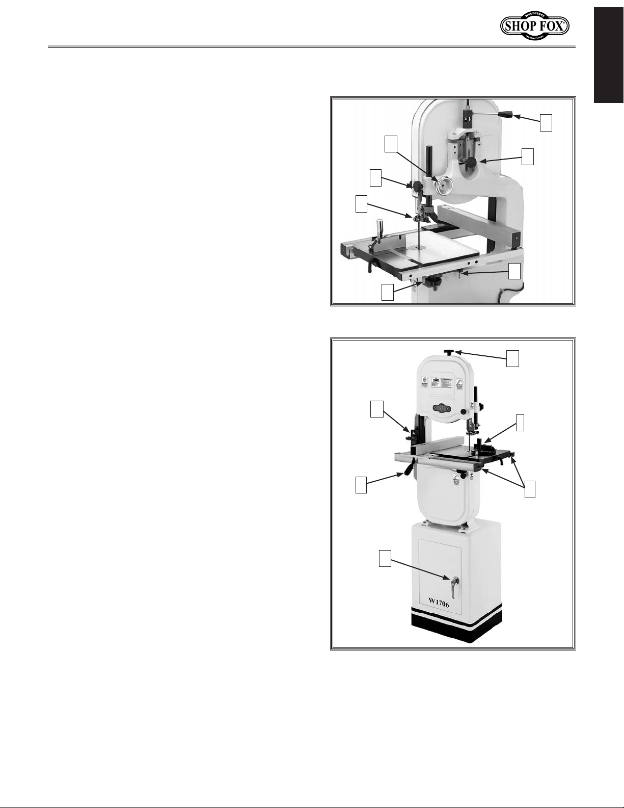
Controls and Features
Refer to Figures 1–2 and the descriptions below to
better understand the controls and features of the
Model W1706.
A. Blade Quick-Release Lever: Quickly releases
or engages blade tension for blade changes.
B. Blade Tracking Knob: Adjusts and locks the
blade tracking.
C. Table Stop: Allows for returning the table to
0° quickly and accurately.
INTRODUCTION
A
G
B
F
E
D. Trunnion Lock Knob: Locks the table in any
tilted position from 45° right to 10° left.
E. Upper Blade Guides: Provides low-friction
support and extended blade life.
F. Blade Guide Lock Knob: Locks the upper
blade guides in place.
G. Guide Post Elevation Handwheel: Moves the
blade guides quickly to the desired height.
H. Blade Tension Knob: Tensions the blade in
gradual increments.
I. Miter Gauge: Provides support for angle cuts.
J. Fence Rails: Front and rear fence rails
provide stable support for the fence.
K. Storage Cabinet: Offers convenient storage
for bandsaw related items.
D
Figure 1. Bandsaw rear view.
M
L
K
C
H
I
J
L. Locking Fence: Provides support when
cutting long workpieces.
M. ON/OFF Buttons: Toggles power ON and OFF
to the motor, and can be locked for safety.
Figure 2. Bandsaw front view.
-3-
Page 8
Model W1706 (Mfg. Since 3/13)
SAFETY
OWNER’S MANUAL.
TRAINED OPERATORS ONLY.
DANGEROUS ENVIRONMENTS.
MENTAL ALERTNESS REQUIRED.
electrical components or improperly grounded
manual uses a series of symbols and signal words intended to convey the level of importance of the
safety messages. The progression of symbols is described below. Remember that safety messages by
SAFETY
For Your Own Safety,
Read Manual Before Operating Machine
The purpose of safety symbols is to attract your attention to possible hazardous conditions. This
SAFETY
themselves do not eliminate danger and are not a substitute for proper accident prevention measures—this responsibility is ultimately up to the operator!
NOTICE
Standard Machinery Safety Instructions
Standard Machinery Safety Instructions
Indicates an imminently hazardous situation which, if not avoided,
WILL result in death or serious injury.
Indicates a potentially hazardous situation which, if not avoided,
COULD result in death or serious injury.
Indicates a potentially hazardous situation which, if not avoided,
MAY result in minor or moderate injury.
This symbol is used to alert the user to useful information about
proper operation of the equipment or a situation that may cause
damage to the machinery.
Read and understand this
owner’s manual BEFORE using machine.
have a higher risk of being hurt or killed. Only
allow trained/supervised people to use this
machine. When machine is not being used,
disconnect power, remove switch keys, or
lock-out machine to prevent unauthorized
use—especially around children. Make
workshop kid proof!
machinery in areas that are wet, cluttered,
or have poor lighting. Operating machinery
in these areas greatly increases the risk of
accidents and injury.
alertness is required for safe operation of
machinery. Never operate under the influence
of drugs or alcohol, when tired, or when
distracted.
Untrained operators
Do not use
Full mental
ELECTRICAL EQUIPMENT INJURY RISKS. You can
be shocked, burned, or killed by touching live
machinery. To reduce this risk, only allow an
electrician or qualified service personnel to
do electrical installation or repair work, and
always disconnect power before accessing or
exposing electrical equipment.
DISCONNECT POWER FIRST. Always disconnect
machine from power supply BEFORE making
adjustments, changing tooling, or servicing
machine. This eliminates the risk of injury
from unintended startup or contact with live
electrical components.
EYE PROTECTION. Always wear ANSI-approved
safety glasses or a face shield when operating
or observing machinery to reduce the risk of
eye injury or blindness from flying particles.
Everyday eyeglasses are not approved safety
glasses.
-4-
Page 9

Model W1706 (Mfg. Since 3/13)
WEARING PROPER APPAREL. Do not wear
HAZARDOUS
HEARING PROTECTION.
REMOVE ADJUSTING TOOLS.
INTENDED USAGE.
AWKWARD POSITIONS.
CHILDREN & BYSTANDERS.
GUARDS & COVERS.
FORCING MACHINERY. Do not force machine. It
will do the job safer and better at the rate for
loss of control. Before starting, verify machine
malfunction, leading to serious personal injury
from heated surfaces, high traffic areas, harsh
clothing, apparel, or jewelry that can become
entangled in moving parts. Always tie back
or cover long hair. Wear non-slip footwear to
avoid accidental slips, which could cause loss
of workpiece control.
DUST. Dust created while using
machinery may cause cancer, birth defects,
or long-term respiratory damage. Be aware of
dust hazards associated with each workpiece
material, and always wear a NIOSH-approved
respirator to reduce your risk.
Always wear hearing
protection when operating or observing
loud machinery. Extended exposure to this
noise without hearing protection can cause
permanent hearing loss.
machinery can become dangerous projectiles
upon startup. Never leave chuck keys,
wrenches, or any other tools on machine.
Always verify removal before starting!
intended purpose—never make modifications
without prior approval from Woodstock
International. Modifying machine or using
it differently than intended will void the
warranty and may result in malfunction or
mechanical failure that leads to serious
personal injury or death!
balance at all times when operating machine.
Do not overreach! Avoid awkward hand
positions that make workpiece control difficult
or increase the risk of accidental injury.
bystanders at a safe distance from the work
area. Stop using machine if they become a
distraction.
Only use machine for its
Tools left on
Keep proper footing and
Keep children and
which it was designed.
NEVER STAND ON MACHINE. Serious injury may
occur if machine is tipped or if the cutting
tool is unintentionally contacted.
STABLE MACHINE. Unexpected movement during
operation greatly increases risk of injury or
is stable and mobile base (if used) is locked.
USE RECOMMENDED ACCESSORIES. Consult
this owner’s manual or the manufacturer for
recommended accessories. Using improper
accessories will increase risk of serious injury.
UNATTENDED OPERATION. To reduce the risk
of accidental injury, turn machine OFF and
ensure all moving parts completely stop
before walking away. Never leave machine
running while unattended.
MAINTAIN WITH CARE. Follow all maintenance
instructions and lubrication schedules to
keep machine in good working condition. A
machine that is improperly maintained could
or death.
CHECK DAMAGED PARTS. Regularly inspect
machine for any condition that may affect
safe operation. Immediately repair or replace
damaged or mis-adjusted parts before
operating machine.
MAINTAIN POWER CORDS. When disconnecting
cord-connected machines from power, grab
and pull the plug—NOT the cord. Pulling the
cord may damage the wires inside, resulting
in a short. Do not handle cord/plug with wet
hands. Avoid cord damage by keeping it away
chemicals, and wet/damp locations.
SAFETY
accidental contact with moving parts or flying
debris—make sure they are properly installed,
undamaged, and working correctly.
Guards and covers reduce
EXPERIENCING DIFFICULTIES. If at any time
you experience difficulties performing the
intended operation, stop using the machine!
-5-
Contact Technical Support at (360) 734-3482.
Page 10
Model W1706 (Mfg. Since 3/13)
Additional Safety for Bandsaws
READ and understand this
entire manual before using
this machine. Serious per-
SAFETY
BLADE CONDITION. Do not operate with dull, cracked or badly worn blade. Dull blades require more
effort to perform the cut and increase the risk of kickback. Inspect blades for cracks and missing
teeth before each use.
HAND PLACEMENT. Never position fingers or hands in line with the blade. If the workpiece or your
hands slip, serious personal injury could occur.
DE REPLACEMENT. To avoid mishaps that could result in operator injury, make sure the blade teeth
BLA
face down toward the table and the blade is properly tensioned and tracked before operating.
SMALL WORKPIECE HANDLING. If your hands slip while holding small workpieces with your fingers
during a cut, serious personal injury could occur. Always support/feed the workpiece with push
sticks, jig, vise, or some type of clamping fixture.
sonal injury may occur
if safety and operational
information is not understood and followed. DO
NOT risk your safety by
not reading!
USE this and other machinery with caution
and respect. Always consider safety first,
as it applies to your individual working
conditions. No list of safety guidelines can
be complete—every shop environment is
different. Failure to follow guidelines could
result in serious personal injury, damage
to equipment or poor work results.
BLADE SPEED. Moving the workpiece against a blade that is not at full speed could cause the blade to
grab the workpiece and draw the operator's hands into the blade. Always allow the blade to come
to full speed before starting the cut.
CUTTING TECHNIQUES. Plan your operation so the blade always cuts to the outside of the workpiece.
DO NOT back the workpiece away from the blade while the saw is running, which could cause
kickback and personal injuries. If you need to back the workpiece out, turn the bandsaw OFF and
wait for the blade to come to a complete stop. DO NOT twist or put excessive stress on the blade
that could damage it.
FEED RATE. To avoid the risk of the workpiece slipping and causing operator injury, always feed stock
evenly and smoothly. DO NOT force or twist the blade while cutting, especially when sawing small
curves.
WORKPIECE MATERIAL. This machine is intended for cutting natural and man-made wood products,
and laminate covered wood products. This machine is NOT designed to cut metal, glass, stone,
tile, etc.
BLADE CONTROL. To avoid serious personal injury, DO NOT attempt to stop or slow the blade with your
hand or the workpiece. Allow the blade to stop on its own.
-6-
Page 11
Model W1706 (Mfg. Since 3/13)
POWER SUPPLY
Circuit Requirements
This machine must be connected to the correct size and
type of power supply circuit, or fire or electrical damage
may occur. Read through this section to determine if
an adequate power supply circuit is available for this
machine. If a correct circuit is not available, you must
have a qualified electrician install one before you can
operate the machine.
A power supply circuit includes all electrical equipment
between the main breaker box or fuse panel in your
building and the incoming power connections at the
machine. The power supply circuit used for this machine
must be sized to safely handle the full-load current drawn
from the machine for an extended period of time.
Full-Load Current Rating
The full-load current rating is the amperage a machine
draws at 100% of the rated output power. On machines
with multiple motors, this is the amperage drawn by the
largest motor or sum of all motors and electrical devices
that might operate at one time during normal operations.
Full-Load Current Rating at 110V .................. 11 A m p s
Full-Load Current Rating at 220V ................. 5.5 Amps
The machine must be properly set up
before it is safe to operate. DO NOT
connect this machine to the power
source until instructed to do so in the
"Test Run" portion of this manual.
ELECTRICAL
DO NOT work on your electrical system
if you are unsure about electrical codes
and wiring! Seek assistance from a
qualified electrician. Ignoring this
warning can cause electrocution, fire,
or machine damage.
Circuit Requirements for 110V (Prewired)
This machine is prewired to operate on a 110V power
supply circuit that has a verified ground and meets the
following requirements:
Circuit Type ............... 110 V/12 0V, 60 Hz, Single-Phase
Circuit Size ............................................. 15 Amps
Plug/Receptacle .................................... NEMA 5 -15
Circuit Requirements for 220V
This machine can be converted to operate on a 220V
power supply. To do this, the motor will need to be
rewired and a new plug installed on the power cord;
refer to the
intended 220V circuit must have a verified ground and
meet the requirements that follow:
Circuit Type ...............220V/240V, 60 Hz, Single-Phase
Circuit Size ............................................. 15 Amps
Plug/Receptacle .................................... NEMA 6 -15
Wiring Diagram on Page 51 for details. The
For your own safety and protection
of property, consult a qualified
electrician if you are unsure about
wiring practices or electrical codes in
your area.
NOTICE
The circuit requirements listed in this
manual apply to a dedicated circuit—
where only one machine will be
running at a time. If this machine will
be connected to a shared circuit where
multiple machines will be running at
the same time, consult a qualified
electrician to ensure that the circuit is
properly sized for safe operation.
-7-
Page 12
Grounding Requirements
Model W1706 (Mfg. Since 3/13)
In the event of certain types of malfunctions or
breakdowns, grounding provides a path of least resistance
for electric current to travel— in order to reduce the risk
of electric shock.
Improper connection of the equipment-grounding wire will
increase the risk of electric shock. The wire with green
insulation (with/without yellow stripes) is the equipmentgrounding wire. If repair or replacement of the power
cord or plug is necessary, do not connect the equipmentgrounding wire to a live (current carrying) terminal.
Check with a qualified electrician or service personnel
if you do not understand these grounding requirements,
or if you are in doubt about whether the tool is
ELECTRICAL
properly grounded. If you ever notice that a cord or
plug is damaged or worn, disconnect it from power, and
immediately replace it with a new one.
For 110V Connection (Prewired)
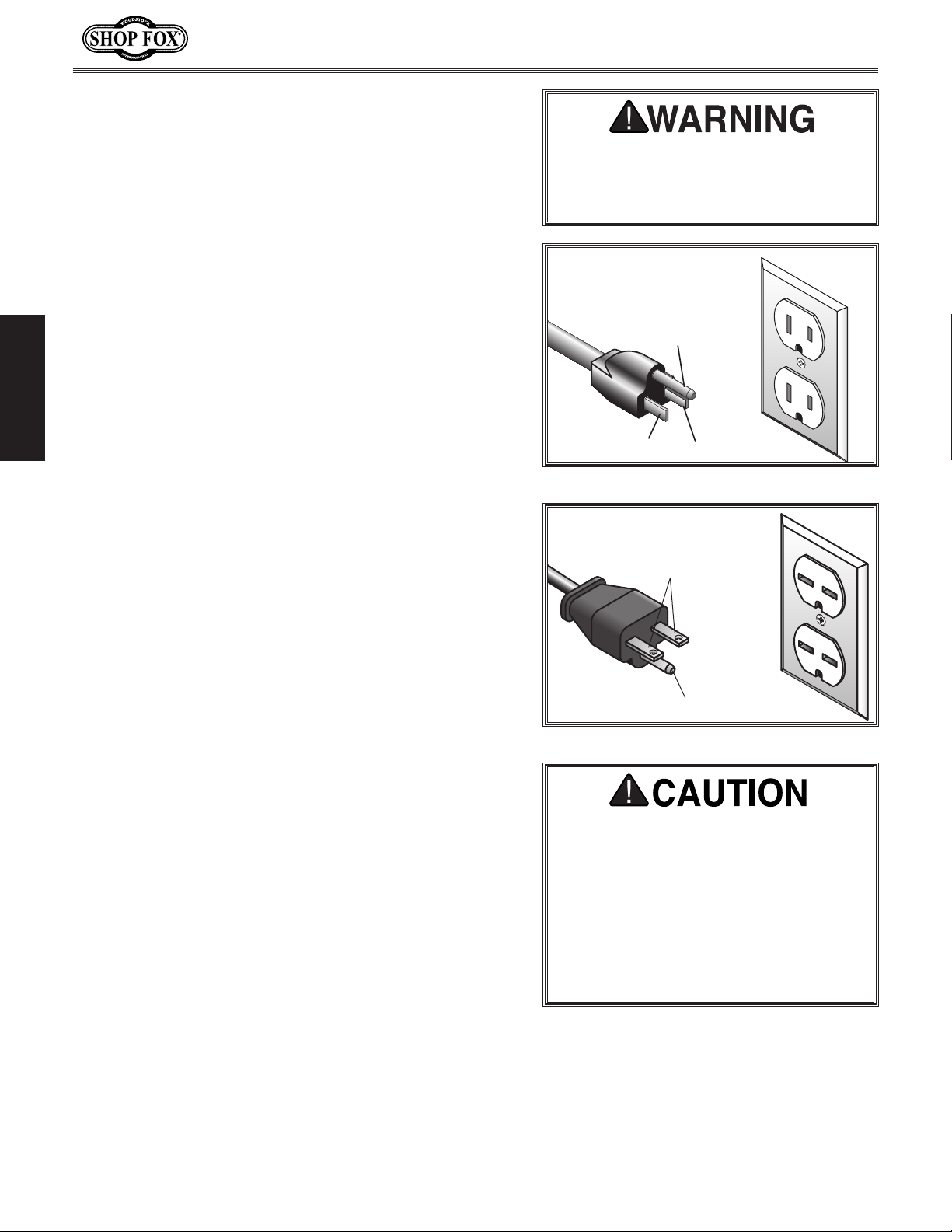
A NEMA 5-15 plug has a grounding prong that must be
attached to the equipment-grounding wire inside the
included power cord. The plug must only be inserted
into a matching receptacle (see
installed and grounded in accordance with all local codes
and ordinances.
Figure 3) that is properly
For 220V Connection (Must Be Rewired)
When converting this machine to 220V operation, you
must properly install a NE M A 6 -15 grounding plug. The
plug must only be inserted into a matching receptacle
Figure 4) that is properly installed and grounded in
(see
accordance with local codes and ordinances.
Extension Cords
We do not recommend using an extension cord with this
machine. Extension cords cause voltage drop, which may
damage electrical components and shorten motor life.
Voltage drop increases with longer extension cords and
the gauge smaller gauge sizes (higher gauge numbers
indicate smaller sizes).
The machine must be properly set up
before it is safe to operate. DO NOT
connect to the power source until
instructed to do so later this manual.
110V
5-15 PLUG
Figure 3. NEMA 5-15 plug & receptacle.
220V
Current Carrying Prongs
6-15 PLUG
Figure 4. NEMA 6-15 plug & receptacle.
DO NOT modify the provided plug or
use an adapter if the plug will not fit
your receptacle. If the machine must be
reconnected for use on a different type
of electric circuit, the reconnection
should be made by qualified service
personnel; and after reconnection,
the machine must comply with all local
codes and ordinances.
GROUNDED
5-15 RECEPTACLE
Grounding Pin
Neutral Hot
GROUNDED
6-15 RECEPTACLE
Grounding Pin
Any extension cord used with this machine must contain a
ground wire, match the required plug and receptacle, and
meet the following requirements:
Minimum Gauge Size .................................. 14 AWG
Maximum Length (Shorter is Better) ..................50 ft.
-8-
Page 13
Model W1706 (Mfg. Since 3/13)
SETUP
Unpacking
This machine has been carefully packaged for safe
transportation. If you notice the machine has been
damaged during shipping, please contact your authorized
Shop Fox dealer immediately.
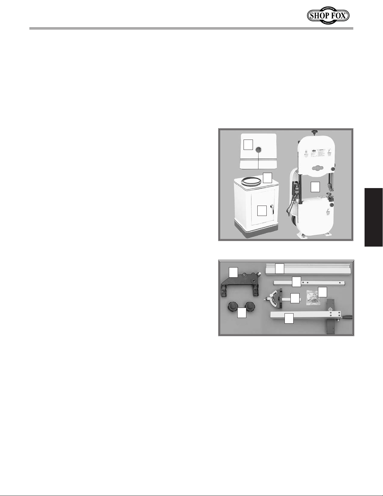
Inventory
The following is a description of the main components
shipped with the Model W1706. Lay the components out
to inventory them.
A
Note: If you can't find an item on this list, check the
mounting location on the machine or examine the
packaging materials carefully. Occasionally we pre-install
certain components for safer shipping.
Inventory (Figures 5–6) Qty
A. Table .........................................................1
B. Saw Blade 6TPI x 3⁄8" x 93 1⁄2" ...........................1
Cabinet Stand ..............................................1
C.
D. Bandsaw Body ..............................................2
E. Trunnion Base ..............................................1
F. Front Fence Rail ...........................................1
Rear Fence Rail ............................................1
G.
H. Hardware Bag:
— Small Table Insert .......................................1
— Large Table Insert .......................................1
— Hex Bolts 5⁄16"-18 x 1 1⁄2" (Bandsaw Body) ...........4
— Hex Nuts 5⁄16"-18 (Bandsaw Body) ....................4
— Lock Washers 5⁄16" (Bandsaw Body) ...................4
— Flat Washers 5⁄16" (Bandsaw Body) ...................4
— Hex Bolts 5⁄8"-18 x 1 1⁄4" (Trunnion Base) ............2
— Lock Washers 5⁄8" (Trunnion Base) ....................2
— Cap Screws 1⁄4"-20 x 5⁄8" (Fence Rail)................2
— Hex Bolts 1⁄4"-20 x 3⁄4" (Fence Rail) ..................2
— Flat Washers 1⁄4" ........................................2
— Combo Wrench 10 x 12mm ............................1
— Hex Wrench 5mm .......................................1
I. Miter Gauge Assembly ....................................1
J. Fence Assembly ............................................1
K. Trunnion Lock Knobs ......................................2
B
C
Figure 5. Inventory A–D.
E
K
Figure 6. Inventory E–K.
F
D
SETUP
G
H
I
J
-9-
Page 14
Model W1706 (Mfg. Since 3/13)
Machine Placement
• Floor Load: This machine distributes a
heavy load in a small footprint. Some
residential floors may require additional
bracing to support both machine and
operator.
• Working Clearances: Consider existing and
anticipated needs, size of material to be
processed through the machine, and space
for auxiliary stands, work tables or other
machinery when establishing a location for
your bandsaw.
• Lighting: Lighting should be bright enough
to eliminate shadow and prevent eye strain.
• Electrical: Electrical circuits must be
dedicated or large enough to handle
amperage requirements. Outlets must be
located near each machine, so power or
extension cords are clear of high-traffic
SETUP
areas. Follow local electrical codes for
proper installation of new lighting, outlets,
or circuits.
Cleaning Machine
The table and other unpainted parts of your
bandsaw are coated with a waxy grease that
protects them from corrosion during shipment.
Clean this grease off with a solvent cleaner or
citrus-based degreaser. DO NOT use chlorinebased solvents such as brake parts cleaner or
acetone—if you happen to splash some onto a
painted surface, you will ruin the finish.
NEVER clean with gasoline
or other petroleumbased solvents. Most have
low flash points, which
make them extremely
flammable. A risk of
explosion and burning
exists if these products
are used. Serious personal
injury may occur if this
warning is ignored!
USE helpers or power
lifting equipment to lift
this Bandsaw. Otherwise,
serious personal injury
may occur.
MAKE your shop “child
safe.” Ensure that your
workplace is inaccessible
to children by closing and
locking all entrances when
you are away. NEVER allow
untrained visitors in your
shop when assembling,
adjusting or operating
equipment.
ALWAYS work in wellventilated areas far from
possible ignition sources
when using solvents to
clean machinery. Many
solvents are toxic when
inhaled or ingested. Use
care when disposing
of waste rags and
towels to be sure they
DO NOT create fire or
environmental hazards.
-10-
Page 15
Model W1706 (Mfg. Since 3/13)
Setup Procedures
Before connecting your bandsaw to power for the first
time and performing the
successfully complete the following tasks in the given
order per the instructions on the referenced pages:
Assemble the bandsaw, as instructed on this page.
1.
2. Connect the bandsaw to an adequate dust collection
system (see Page 13).
Adjust the blade tracking, as instructed on Page 14.
3.
Test R u n on Page 16, you MUST
Assembly
The assembly procedure consists of attaching the bandsaw
body to the cabinet stand, installing the trunnion base
and table, and attaching the fence rails to the table.
To assemble the bandsaw, do these steps:
1. Place the cabinet stand in the working location.
— If you plan to mount the bandsaw on a mobile
base, put the stand on it now and secure the
mobile base so that it cannot move for the
remainder of the setup.
With the help of another person, carefully place the
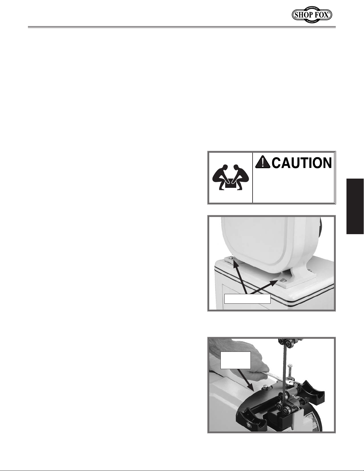
2.
bandsaw body on the cabinet stand and align the
mounting holes (see
Secure the bandsaw body to the cabinet with (4)
3.
5
⁄16"-18 x 1 1⁄2" hex bolts, 5⁄16" lock washers, 5⁄16" flat
washers, and
The trunnion base supports the table and enables it
to be tilted at any angle from 45° right to 10° left.
5
⁄16-18 hex nuts.
Figure 7).
The bandsaw is a
heavy load. Get lifting
assistance before you
begin this step.
Mounting Bolts
Figure 7. Bandsaw body mounted on the
cabinet stand.
SETUP
Position the trunnion base on the bandsaw body as
4.
shown in Figure 8, then secure it in place with (2)
5
⁄16"-18 x 1 1⁄4" hex bolts and 5⁄16" lock washers.
Trunnion
Base
Figure 8. Installing the trunnion base.
-11-
Page 16
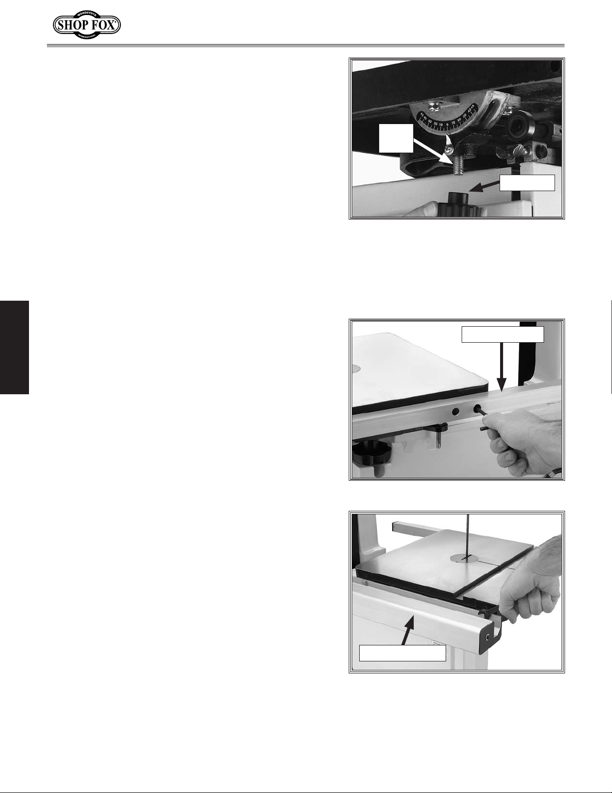
5. Remove the insert and the table slot locking pin
from the table.
Line up the table slot with the blade, position the
6.
table so that the blade is in the center cut-out.
Rotate the table so that the table slot faces to
7.
the right, then insert the table bolts through the
mounting holes in the trunnion base, as shown in
Figure 9.
Secure the table by fully threading the two trunnion
8.
lock knobs onto the table bolts.
Replace the table insert and locking pin.
9.
Important: Make sure you re-install the table slot
locking pin. This pin keeps the table surfaces on
either side of the slot even with the changes in
operating pressures and temperature changes.
Model W1706 (Mfg. Since 3/13)
Table
Bolt
Lock Knob
Figure 9. Installing the table onto the
trunnion base.
Attach the smaller rear fence rail to the rear of the
10.
table with (2) 1/4"-20 x 5⁄8" cap screws, as shown in
SETUP
Figure 10.
11. Attach the larger front fence rail shown in Figure
11, with (2) 1⁄4"-20 x 3⁄4" hex bolts and 1⁄4" flat
washers.
Rear Fence Rail
Figure 10. Installing rear fence rail.
-12-
Front Fence Rail
Figure 11. Installing front fence rail.
Page 17
Model W1706 (Mfg. Since 3/13)
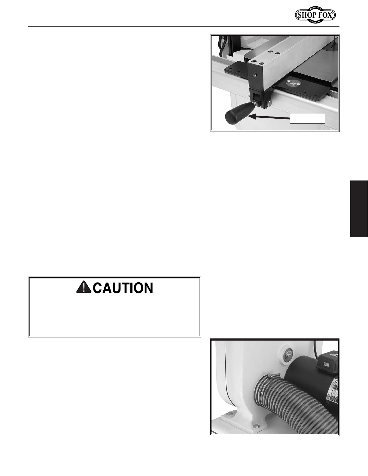
12. Place the fence assembly onto the front rail and
position it to the left of the table insert, then secure
it in place by pressing down on the lock lever (see
Figure 12).
Dust Collection
Recommended CFM at Dust Port: ................ 400 CFM
Lock Lever
Figure 12. Fence secured in place.
Do not confuse this CFM recommendation with the rating
of the dust collector. To determine the CFM at the
dust port, you must take into account many variables,
including the CFM rating of the dust collector, the length
of hose between the dust collector and the machine, the
amount of branches or Y's, and the amount of other open
lines throughout the system. Explaining this calculation
is beyond the scope of this manual. If you are unsure of
your system, consult an expert or purchase a good dust
collection "how-to" book.
DO NOT operate this machine without an adequate
dust collection system. This machine creates substantial amounts of wood dust while operating. Failure to
use a dust collection system can result in short and
long-term respiratory illness.
To connect a dust collection hose, do these steps:
1. Slide a 4" dust hose over the dust port and secure it
in place with a hose clamp, as shown in Figure 13.
SETUP
Tug on the hose to make sure it is secure.
2.
Note: A tight fit is necessary for proper dust
collection.
Figure 13. Dust collection hose connected
to the dust port.
-13-
Page 18
Blade Tracking
Blade tracking is affected by the tilt of the upper wheel
(known as center tracking) and the alignment of both
wheels (known as coplanar tracking).
The wheels on this bandsaw were aligned at the factory,
so center tracking is the only adjustment that needs to be
performed when the saw is new (refer to
on Page 47 for detailed instructions on coplanar tracking).
Note: Changes in the blade tension may change the
blade tracking. For best performance, regularly check and
maintain the proper blade tracking.
To center track the blade, do these steps:
1. DISCONNECT BANDSAW FROM POWER!
2. Adjust the upper and lower blade guides away from
the blade (refer to Adjusting Blade Guide Bearings
Page 24 for detailed instructions).
on
Aligning Wheels
Model W1706 (Mfg. Since 3/13)
NOTICE
If, after properly performing the blade
tracking procedure, the blade is still
not tracking correctly, refer to Aligning
Wheels
solutions.
on Page 47 for additional
SETUP
Note: When adjusting the blade tracking for the
test run in this procedure, the blade must have a
reasonable amount of tension to simulate operating
conditions. After the test run is successfully
completed, you will perform a thorough version of
the following steps to correctly tension the blade.
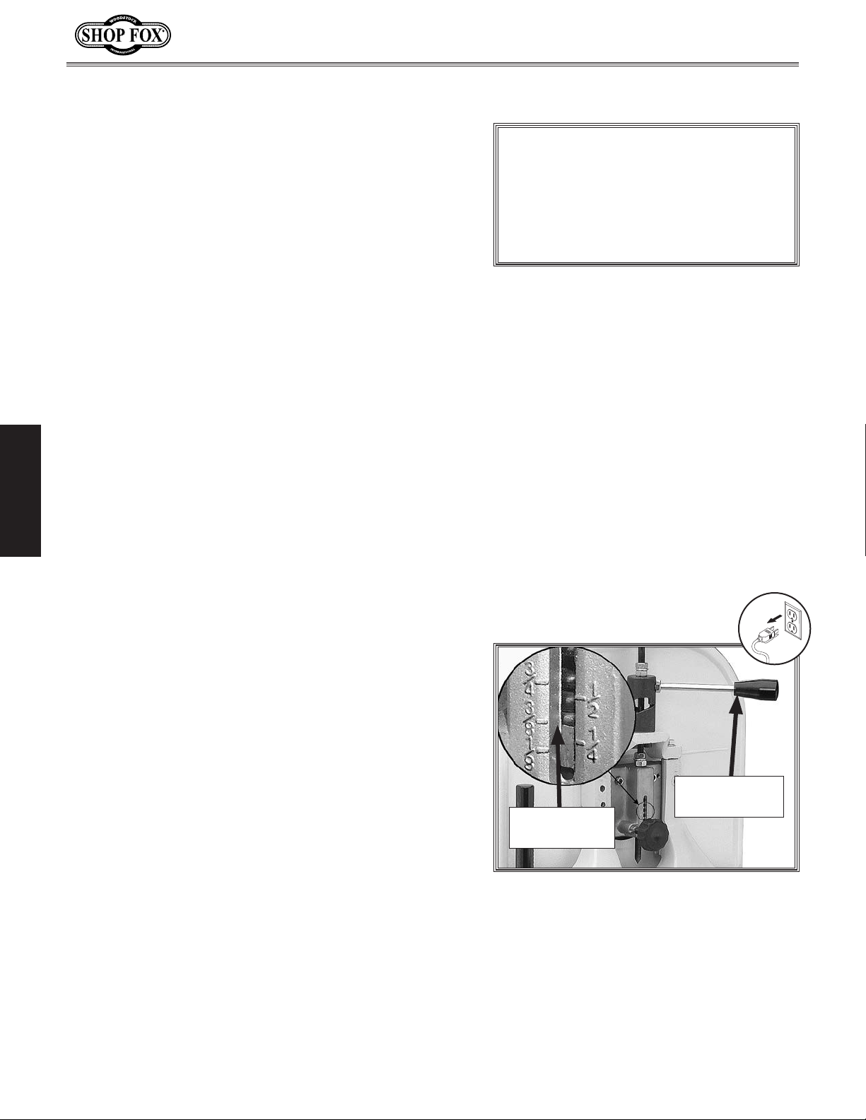
Move the blade tension quick release lever all the
3.
way right (as viewed from the rear of the machine)
to apply tension to the blade (see
Use the tension knob on top of the bandsaw to
4.
bring the upper edge of the indicator block to the
appropriate blade tension scale mark for the blade
width (see
Note: If you are using the blade that was shipped
with the machine, this would be
Open the upper wheel cover.
5.
Figure 14).
Figure 14).
3
⁄8".
Quick Release
Tensioned for
3
⁄8" Blade
a
Figure 14. Tension applied for a 3⁄8" blade.
Lever
-14-
Page 19
Model W1706 (Mfg. Since 3/13)
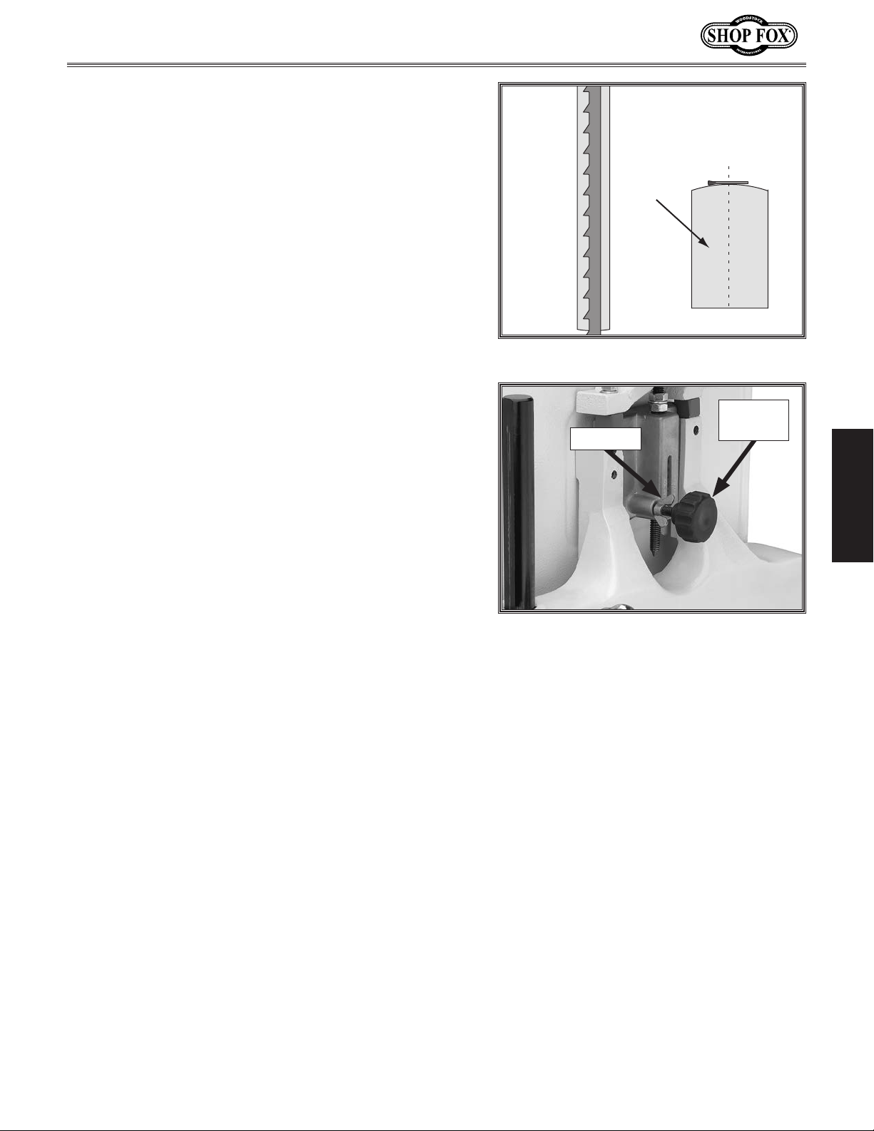
6. Rotate the upper wheel by hand several times (at
least three) and watch how the blade rides on the
wheel crown. See
this concept.
— If the blade rides in the center of the upper wheel
and is centered on the peak of the wheel crown,
then the bandsaw is already properly centertracked and no further tracking adjustments are
needed at this time.
— If the blade does NOT ride in the center of the
upper wheel and is not centered on the peak
of the wheel crown, then continue with this
procedure.
Loosen the wing nut on the tracking knob (see
7.
Figure 16), then rotate the knob a small amount.
Note: When the tracking knob is rotated, the lower
portion of the upper wheel will tilt out or in, which
affects the way the blade tracks.
Figure 15 for an illustration of
CENTER TRACKING
Blade Centered
on Peak of Crown
Blade
Centered
on Wheel
Figure 15. Blade center tracking.
Wing Nut
Wheel
Tracking
Knob
SETUP
Spin the upper wheel with one hand and slowly
8.
adjust the tracking knob with the other until the
blade rides in the center of the wheel tire without
wandering.
Tighten the wing nut to secure the setting, then spin
9.
the upper wheel again to confirm the tracking. If
necessary, repeat
with the blade tracking.
Re-adjust the blade guide bearings toward the blade
10.
(refer to Adjusting Blade Guide Bearings on Page
24 for detailed instructions).
Close and secure the upper wheel cover before
11.
beginning operation.
Steps 6–8 until you are satisfied
Power Connection
Before the machine can be connected to the power
source, an electrical circuit and connection device must
be prepared per the
and all previous setup instructions in this manual must be
complete to ensure that the machine has been assembled
and installed properly.
Always make sure the OFF button is pushed in before
con n ec t ing p ow e r.
POWER SUPPLY section on Page 7,
Figure 16. Tracking knob and wing nut.
Insert the plug attached to the machine
power cord into a matching power supply
receptacle. The machine is now connected
to the power source.
If you need to disconnect the machine from
power later, pull the plug completely out of
the receptacle.
-15-
Page 20
Test Run
Once the assembly is complete, test run your machine to
make sure it runs properly.
If, during the test run, you cannot easily locate the source
of an unusual noise or vibration, stop using the machine
immediately, then review the Troubleshooting on
52.
Page
Model W1706 (Mfg. Since 3/13)
If you still cannot remedy a problem, contact our Tech
Support at (360) 734-3482 for assistance.
To test run the machine, do these steps:
1. Make sure you understand the safety instructions
at the beginning of the manual, and verify that the
machine is setup properly.
Ensure all tools and objects used during set up are
2.
cleared away from the machine.
Turn the machine ON.
3.
SETUP
Listen to and watch for abnormal noises or actions.
4.
The machine should run smoothly with little or no
vibration or rubbing noises.
— Strange or unusual noises should be investigated
and corrected before operating the machine
further. Always disconnect the machine from
power when investigating or correcting potential
problems.
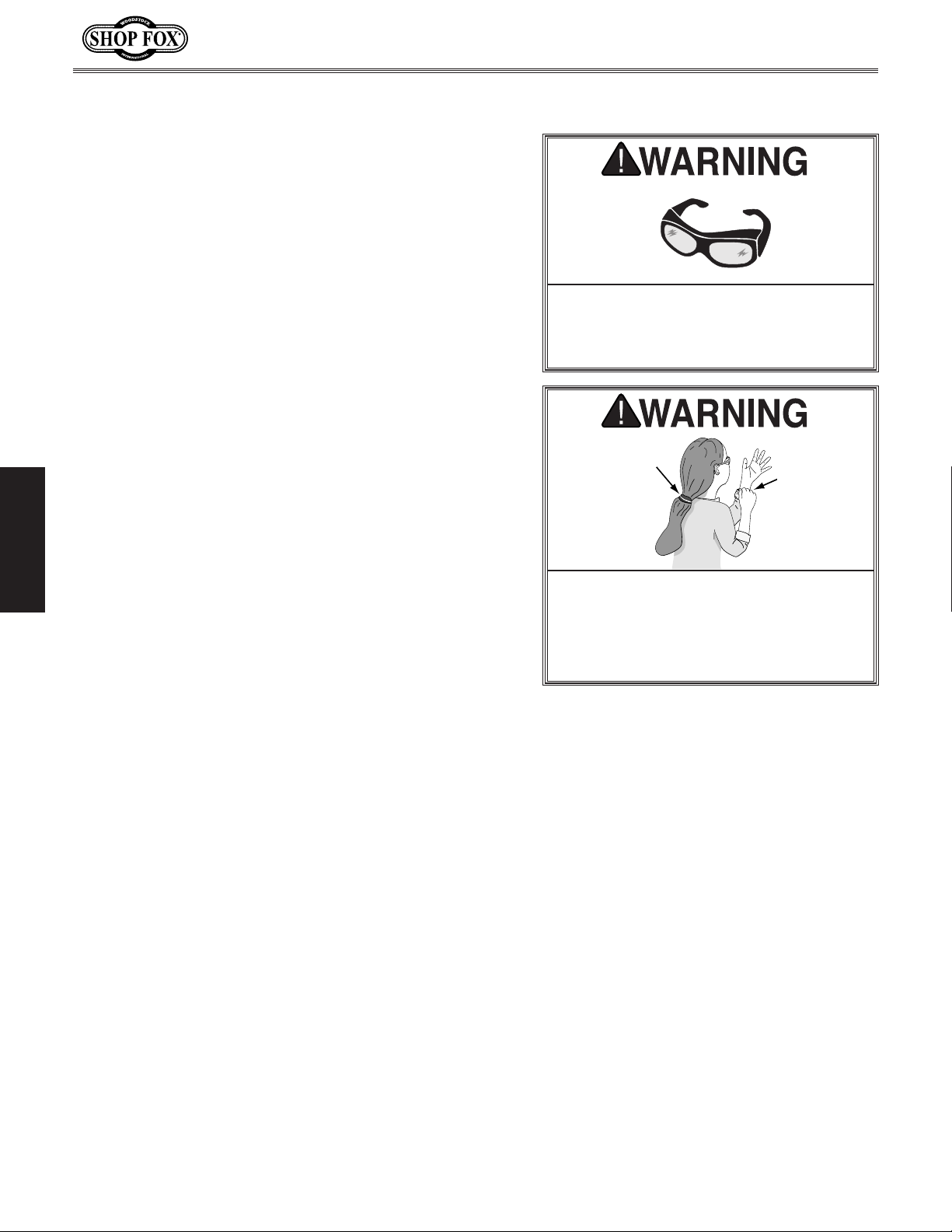
Projectiles thrown from the machine
could cause serious eye injury. Wear
safety glasses to reduce the risk of
injury.
Loose hair and clothing could get
caught in machinery and cause serious
personal injury. Keep loose clothing
rolled up and long hair tied up and
away from machinery.
Turn the machine OFF.
5.
Additional Adjustments
After successfully completing the Test Run, the
adjustment procedures listed below must be performed to
ensure safe and accurate cutting operations (refer to the
following subsections for detailed instructions):
• Properly tension the blade (Page 17).
• Adjust the positive stop bolt (Page 18).
• Align the table with the blade (Page 19).
• Square the miter gauge body to the blade (Page 20).
• Align the fence with the blade (Page 21).
• Adjusting the blade support bearings (Page 22).
• Adjusting the blade guide bearings (Page 24).
-16-
Page 21
Model W1706 (Mfg. Since 3/13)
Tensioning Blade
A properly tensioned blade is essential for making
accurate cuts, extending the life of the blade, and
making many other bandsaw adjustments. For instance,
every time you replace the blade, you must perform this
procedure because all blades tension differently.
Note: Before you performed the Test R u n, you set the
blade to its approximate tension. The following procedure
fine-tunes the blade tension to ensure accurate cutting
results.
To correctly tension the bandsaw blade, do these steps:
1. DISCONNECT BANDSAW FROM POWER!
2. Move the upper and lower guide/support bearings
as far away from the blade as possible (refer to
Adjusting Blade Guide Bearings on Page 24 for
detailed instructions).
SETUP
Note: This procedure will NOT work correctly if
the guide/support bearings are in contact with the
blade.
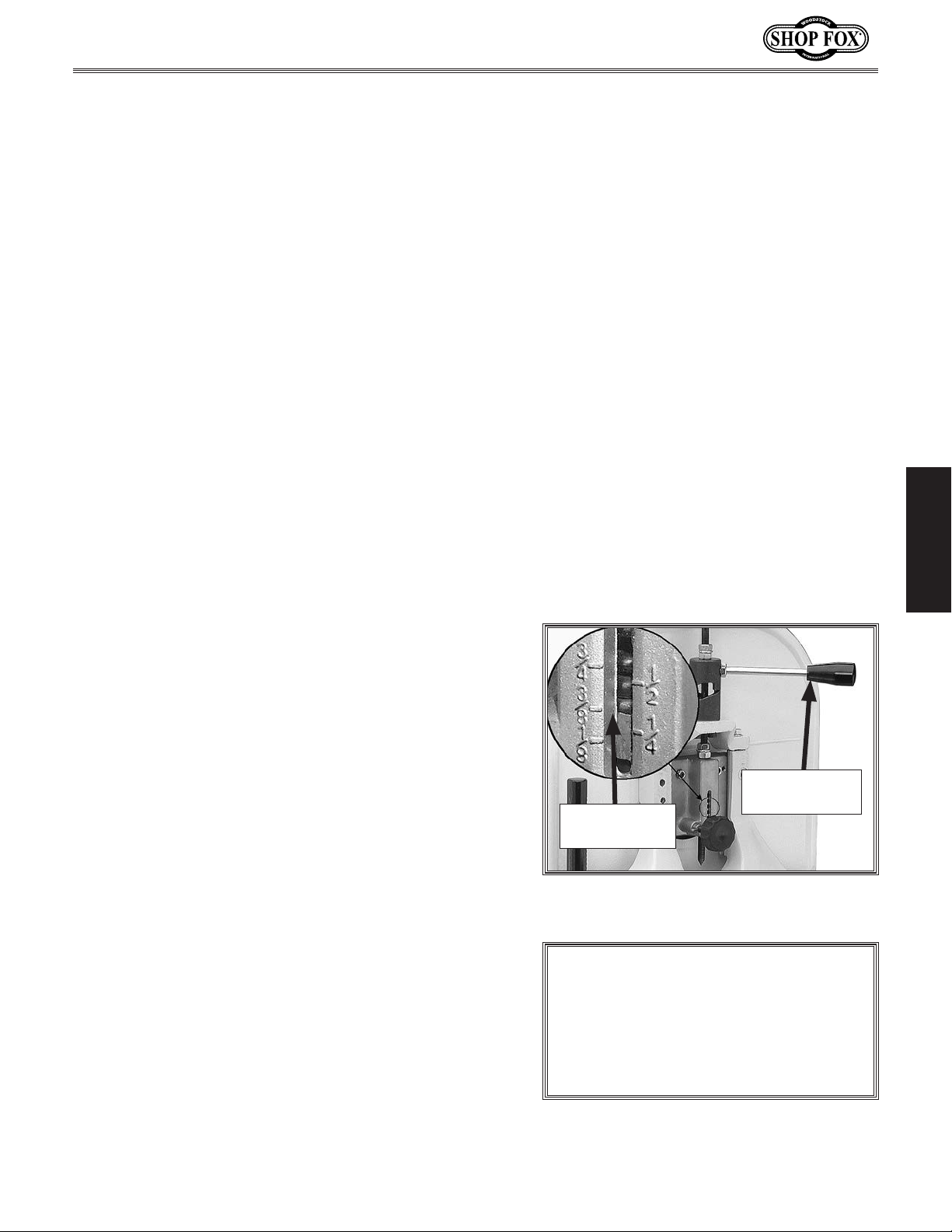
Move the blade tension quick release lever all the
3.
way right (as viewed from the rear of the machine)
to apply tension to the blade (see
Use the tension knob on top of the bandsaw to
4.
bring the upper edge of the indicator block to the
appropriate blade tension scale mark for the blade
width (see
Re-connect the bandsaw to power, then turn it ON
5.
and wait for the blade to reach full speed.
Decrease blade tension very slowly by rotating the
6.
tension knob counterclockwise (as viewed from
above) until the blade just starts to flutter or
vibrate, then stop decreasing the tension.
Now, increase the tension by rotating the knob in
7.
the opposite direction (clockwise) until the blade
stops fluttering, then rotate the knob another
turn clockwise.
Turn the bandsaw OFF.
8.
Figure 17).
Figure 17).
1
⁄4
Quick Release
Tensioned for
3
⁄8" Blade
a
Figure 17. Example of tension control
settings
Lever
NOTICE
When not in use, move the tension
quick release lever to the left to
release blade tension, which will
increase blade life and reduce machine
wea r.
Re-adjust the blade tracking (refer to Page 14) and
9.
the blade guides (refer to
Pages 22 and 24).
-17-
Page 22
Adjusting Positive Stop
After using the table at a tilt of other than 0°, the
positive stop allows the table to be quickly and accurately
returned to the horizontal position in relation to the
blade. This is important for accurate cutting results.
Note: The height of the positive stop is lowered when the
table is tilted to the left. Properly re-adjust the positive
stop after returning the table to 0° or greater.
Tools Needed Qty
Wrench 13mm
Machinist's Square
Phillips Screwdriver.............................................1
To adjust the positive stop, do these steps:
1. Make sure the blade is properly tensioned as
instructed on the previous page.
...................................................1
..............................................1
Model W1706 (Mfg. Since 3/13)
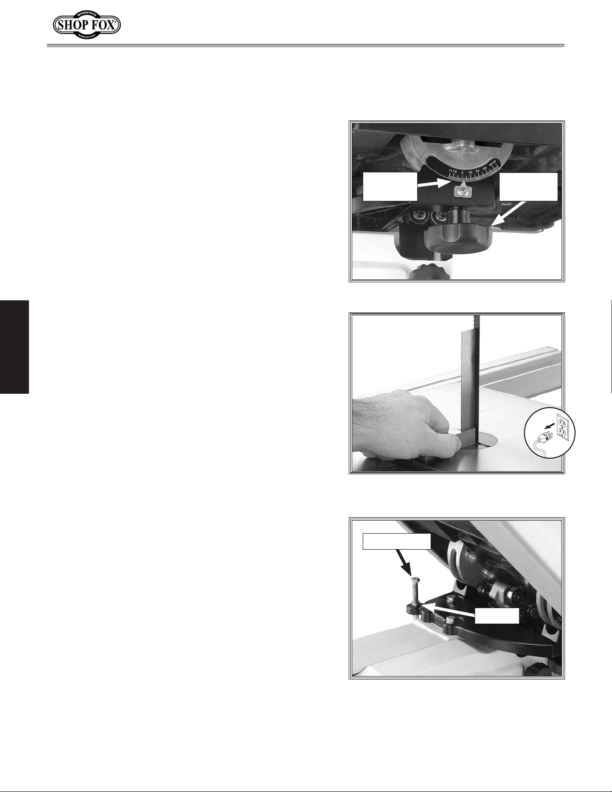
Tilt Scale
& Pointer
Figure 18. Table tilt controls.
Lock Knob
(1 of 2)
DISCONNECT BANDSAW FROM POWER!
2.
SETUP
3. Place the machinist's square flat on the table and
against the side of the blade, as shown in Figure 19.
— If the square sits on the table and against the
blade without any gaps, no adjustments are
necessary.
— If there are gaps between the square, table, and
blade, continue with Step 4.
Loosen both trunnion lock knobs (see Figure 18) to
4.
allow the table to tilt.
Loosen the hex nut on the positive stop shown in
5.
Figure 20, then adjust the height of the positive
stop until the square is flat against the table and
blade.
When you are satisfied with the setting, re-tighten
6.
the hex nut to secure the positive stop in place.
Figure 19. Using a machinist's square to
adjust the table tilt.
Positive Stop
Hex Nut
Loosen the screw on the tilt scale pointer shown in
7.
Figure 18, then align the pointer with the "0" on the
scale before re-tightening the screw.
-18-
Figure 20. Positive stop (table tilted to
the right for photo clarity).
Page 23
Model W1706 (Mfg. Since 3/13)
Aligning Table
To ensure cutting accuracy when the table is first
installed, the table should be aligned so the miter slot is
parallel to the bandsaw blade. This procedure works best
with a
Tools Needed Qty
Wrench or Socket 10mm
Straightedge 24"
Fine Ruler 12"
To align the miter slot parallel to the bandsaw blade,
do these steps:
1. Make sure that the blade is correctly tensioned
2.
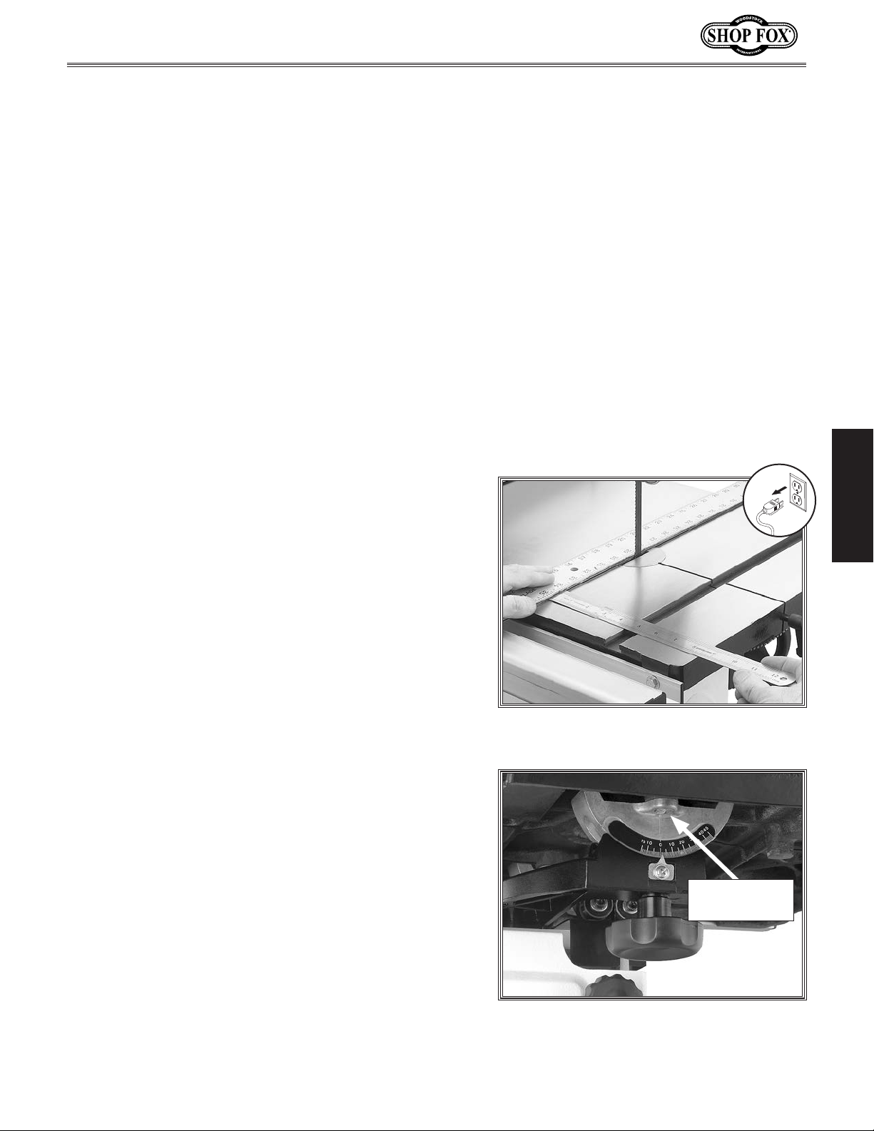
3. Place an accurate straightedge along the blade. The
3
⁄4" blade.
.......................................1
................................................1
...................................................1
(refer to Page 17) and is tracking properly (refer to
Page 14).
DISCONNECT BANDSAW FROM POWER!
straightedge should lightly touch both the front and
back of the blade without resting on a tooth (see
Figure 21). Take care not to move the blade in this
step.
SETUP
Use a fine ruler to gauge the distance between the
4.
blade and the miter slot. The distance you measure
should be the same at both the front and back ends
of the miter slot.
— If the measurements at the front and back ends of
the miter slot are the same, no adjustments are
necessary.
— If the measurements are not the same, continue
with Step 5.
Loosen the six trunnion bolts that secure the
5.
trunnions to the table (see Figure 22).
Adjust the table as needed until the distance
6.
between the blade and miter slot is equal at both
ends, as measured in
Tighten the trunnion bolts to secure the setting.
7.
Step 4.
Figure 21. Taking measurements for
aligning the table with the blade.
Trunnion Bolt
(1 of 6)
-19-
Figure 22. Location of trunnion bolt.
Page 24
Aligning Miter Gauge
Body
To ensure accurate cutting results when using the miter
gauge, the miter gauge body must be aligned with the
blade.
Tools Needed Qty
Machinist's Square
Phillips Screwdriver.............................................1
To align the miter gauge body, do these steps:
1. Install the widest blade possible, then make sure the
blade is properly tensioned (refer to
tracking correctly (refer to
DISCONNECT BANDSAW FROM POWER!
2.
..............................................1
Page 17) and is
Page 14).
Model W1706 (Mfg. Since 3/13)
3. Make sure the table is properly aligned with the
blade (refer to Page 19).
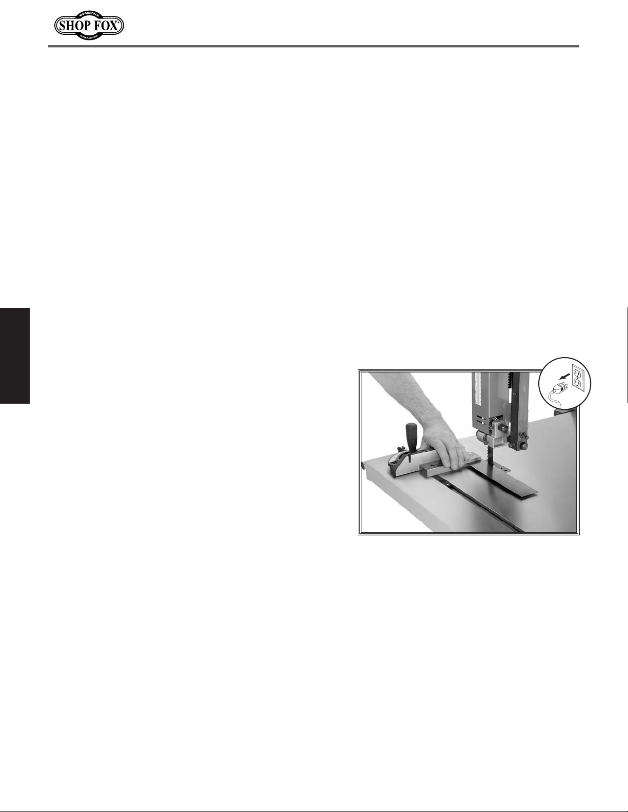
Lay the machinist's square flat on the table and up
4.
SETUP
against the blade without touching any blade teeth
Figure 23 for an example).
(see
Without moving the square, bring the miter gauge
5.
body up to the square.
— If there are no gaps between the miter gauge body
and the square, no adjustments are needed.
— If there are gaps between the miter gauge body
and the square, continue with this procedure.
Loosen the miter gauge lock knob and rotate the
6.
gauge body until it is flat against the square, then
re-tighten the lock knob.
Loosen the screw that secures the miter gauge
7.
pointer, set the pointer to the 0° mark on the scale,
then re-tighten the screw.
Figure 23. Aligning the miter gauge body
with the blade.
-20-
Page 25
Model W1706 (Mfg. Since 3/13)
Adjusting Fence
The fence must be aligned with the blade to ensure
accurate cutting results. This is best done by aligning
the fence with the miter slot after the table is properly
aligned.
Tools Needed Qty
Hex Wrench 5mm
Wrench 10mm
To align the fence with the miter slot, do these steps:
1. DISCONNECT BANDSAW FROM POWER!
...............................................1
...................................................1
2. Make sure the table is properly aligned with the
blade (refer to Page 19).
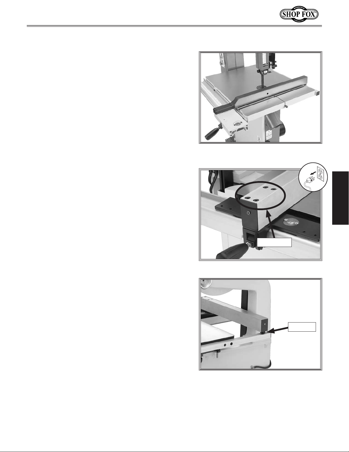
Mount the fence on the right side of the blade
3.
and even with the miter slot (see Figure 24 for an
example).
— If the fence face is even with the miter slot from
front-to-back, skip to Step 5.
— If the fence face is not even with the miter slot
along its length, continue with Step 4.
Loosen the four cap screws shown in Figure 25,
4.
adjust the fence until it is even with the miter slot
from front-to-back, then re-tighten the cap screws
to secure the setting.
Note: If cuts are tapered after aligning the fence
with the miter slot, refer to Blade Lead on
Page 46.
Note the gap between the fence and the table along
5.
the entire length of the blade.
— If the gap is not even, loosen the hex nut on the
rub foot (see Figure 26), adjust the foot in or
out until the gap is even along the length of the
fence. When you are satisfied, re-tighten the hex
nut to secure the setting.
Figure 24. Example of aligning the fence
with the table miter slot.
SETUP
Cap Screws
Figure 25. Fence alignment cap screws.
Rub Foot
-21-
Figure 26. Fence rub foot.
Page 26
Adjusting Blade Support
Bearings
The support bearings are positioned behind the blade and
support the back of the blade during cutting operations.
Proper adjustment of the support bearings is an important
part of making accurate cuts and also keeps the blade
teeth from coming in contact with the guide bearings
while cutting. There are support bearings on the upper
lower blade guide assemblies—both sets adjust in the
same manner.
To adjust the support bearings, do these steps:
Model W1706 (Mfg. Since 3/13)
NOTICE
Whenever changing a blade or adjusting
the tension or tracking, the upper and
lower blade support bearings and guide
bearings must be properly adjusted
before cutting operations.
1. Make sure that the blade is correctly tensioned
(refer to Page 17) and is tracking properly (refer to
Page 14).
DISCONNECT BANDSAW FROM POWER!
2.
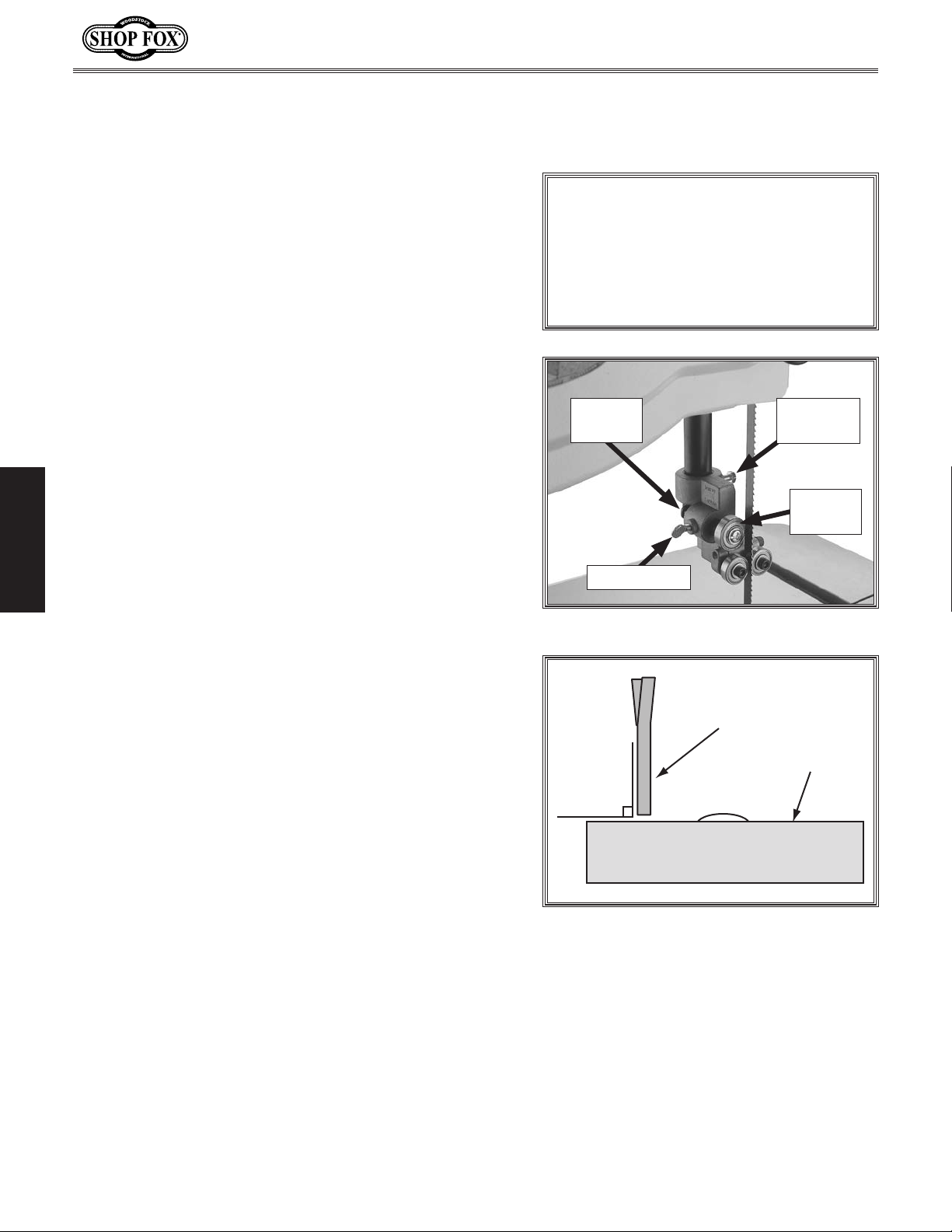
3. Familiarize yourself with the blade support bearing
controls shown in Figure 27.
SETUP
Loosen the assembly lock bolt.
4.
5. Look at the face of the support bearing and rotate
the blade guide assembly side-to-side, until the
blade is perpendicular with the face of the support
bearing, as illustrated in
Re-tighten the assembly lock bolt to secure the
6.
setting.
Figure 28.
Knurled
Knob
Thumbscrew
Figure 27. Blade support bearing controls.
Blade
90°
Assembly
Lock Bolt
Support
Bearing
Support
Bearing
-22-
Figure 28. Support bearing perpendicular
to the blade.
Page 27
Model W1706 (Mfg. Since 3/13)
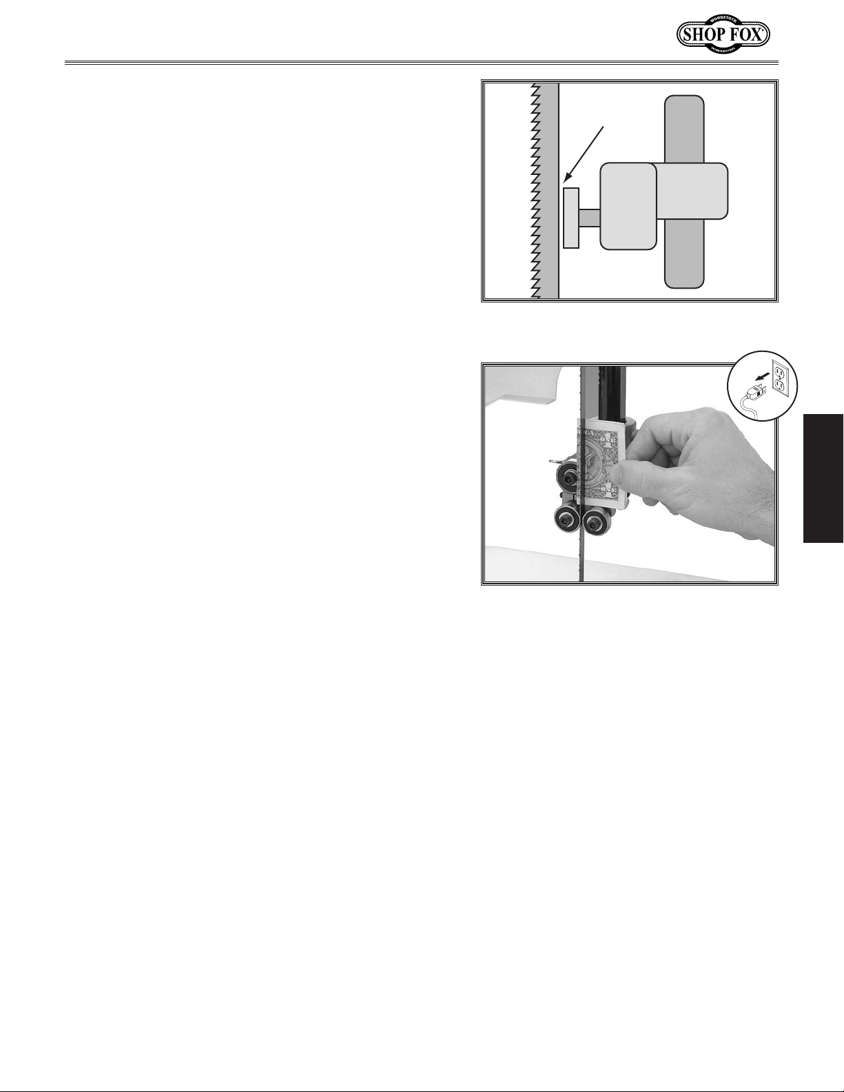
7. Loosen the thumbscrew on the support bearing
adjustment shaft (see Figure 27).
Use the knurled knob to position the support
8.
bearing approximately 0.016" away from the back of
the blade, as illustrated in
Tip: For a quick gauge, fold a crisp dollar bill
in half twice (four thicknesses of a dollar bill
is approximately 0.016") and place it between
the support bearing and the blade, as shown in
Figure 30.
Figure 29.
0.016"
Re-tighten the thumbscrew to keep the support
9.
bearing locked in place.
Figure 29. Support bearing positioned
0.016" away from the back of the blade.
SETUP
Figure 30. Dollar bill folded twice in half
for a quick 0.016" gauge.
-23-
Page 28
Adjusting Blade Guide
Bearings
The blade guides provide side-to-side support to keep
the blade straight while cutting. The blade guides are
designed to be adjusted in two ways—forward/backward
and side-to-side. Properly adjusted blade guides are
essential to making accurate cuts.
Tools Needed Qty
Hex Wrench 4mm
...............................................1
Model W1706 (Mfg. Since 3/13)
NOTICE
Whenever changing a blade or adjusting
the tension or tracking, the upper and
lower blade support bearings and guide
bearings must be properly adjusted
before cutting operations.
To adjust the blade guide bearings, do these steps:
1. Make sure that the blade is correctly tensioned
(refer to Page 17) and is tracking properly (refer to
Page 14).
DISCONNECT BANDSAW FROM POWER!
2.
3. Familiarize yourself with the blade guide bearing
controls shown in Figure 31.
SETUP
Loosen the thumbscrew.
4.
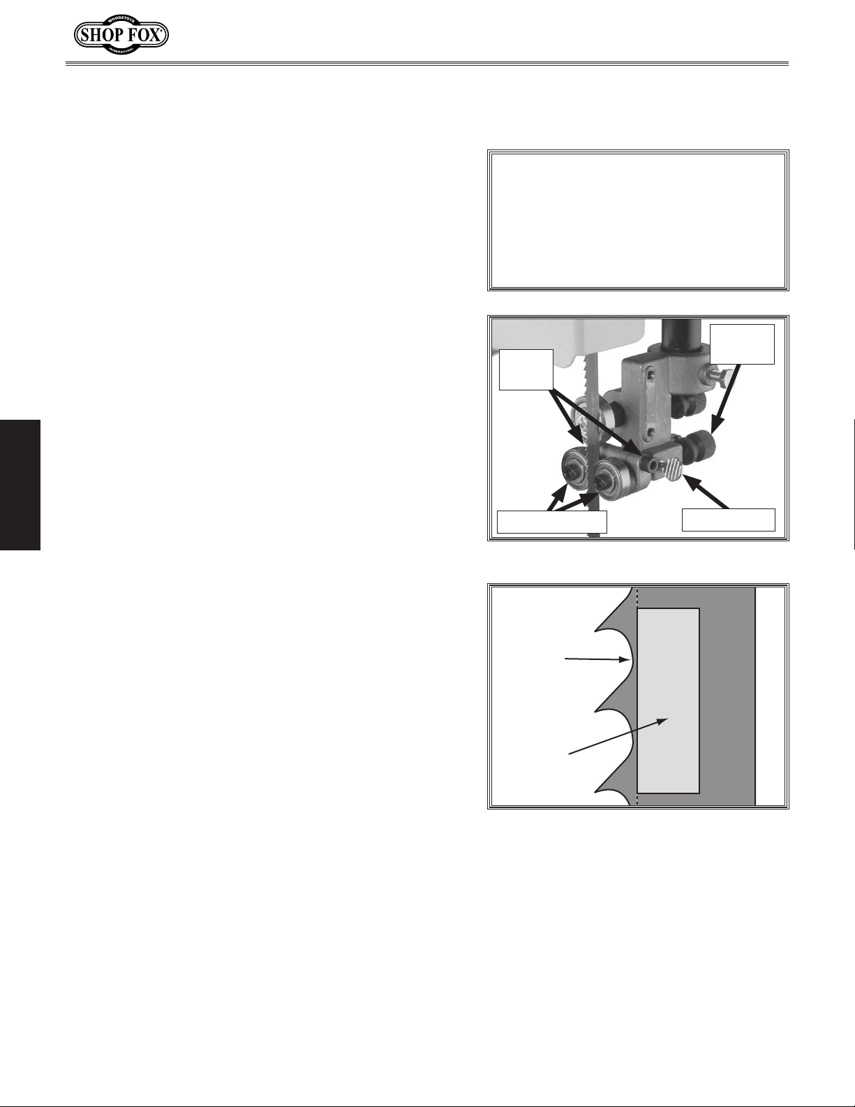
5. Rotate the knurled knob behind the blade guide
bearings to position them so that the edges of the
bearings are as forward as possible without going
past the gullets (see the illustration in
Note: The goal in this step is to position the guide
bearing so that when the blade is deflected back
against the support bearing it will not come in
contact the blade teeth.
Figure 32).
Knurled
Cap
Screws
Guide Bearings
Figure 31. Blade guide bearing controls.
Blade
Gullet
Knob
Thumbscrew
When you are satisfied with the guide bearing
6.
positions, re-tighten the thumbscrew.
Guide
Bearing
Figure 32. Guide bearing positioned
behind the blade gullets.
-24-
Page 29
Model W1706 (Mfg. Since 3/13)
7. Loosen the cap screws behind the guide bearings
(see Figure 31), then open the upper wheel cover.
Rotate the upper wheel with one hand, and use the
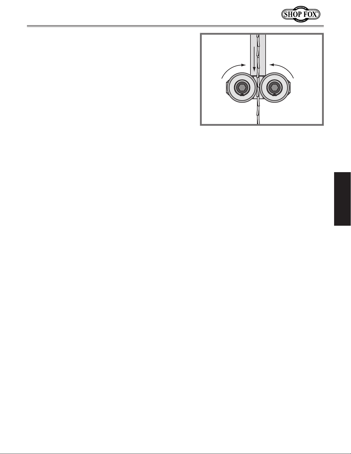
8.
hex wrench to rotate the eccentric guide bearings
until they just begin to rotate with the blade (see
Figure 33). The guides should just lightly touch the
blade.
When you are satisfied with blade guide bearing
9.
positions, re-tighten the cap screws behind them to
secure the settings.
Figure 33. Rotating the blade guide
bearings toward the blade.
SETUP
-25-
Page 30
OPERATIONS
General
This machine will perform many types of operations
that are beyond the scope of this manual. Many of these
operations can be dangerous or deadly if performed
incorrectly.
The instructions in this section are written with the
understanding that the operator has the necessary
knowledge and skills to operate this machine.
time you are experiencing difficulties performing any
operation, stop using the machine!
If you are an inexperienced operator, we strongly
recommend that you read books or trade articles, or seek
training from an experienced Bandsaw operator before
performing any unfamiliar operations.
safety should come first!
Above all, your
If at any
Model W1706 (Mfg. Since 3/13)
READ and understand this entire instruction manual before using this machine.
Serious personal injury may occur if
safety and operational information is not
understood and followed. DO NOT risk
your safety by not reading!
OPERATIONS
DO NOT investigate problems or adjust
the machine while it is running. Wait
until the machine is turned OFF,
unplugged and all working parts
have come to a complete stop before
proceeding!
Damage to your eyes and lungs could
result from using this machine without
proper protective gear. Always wear
safety glasses and a respirator when
operating this machine.
-26-
Page 31
Model W1706 (Mfg. Since 3/13)
Operation Overview
The purpose of this overview is to provide the novice
machine operator with a basic understanding of how
the machine is used during operation, so the machine
controls/components discussed later in this manual are
easier to understand.
Due to the generic nature of this overview, it is not
intended to be an instructional guide. To learn more
about specific operations, read this entire manual and
seek additional training from experienced machine
operators, and do additional research outside of this
manual by reading "how-to" books, trade magazines, or
web sites.
To complete a typical operation, the operator does the
following:
Examines the workpiece to make sure it is suitable
1.
for cutting.
Adjusts the fence for the width of the cut and then
2.
locks it in place.
Disabling & Locking
Switch
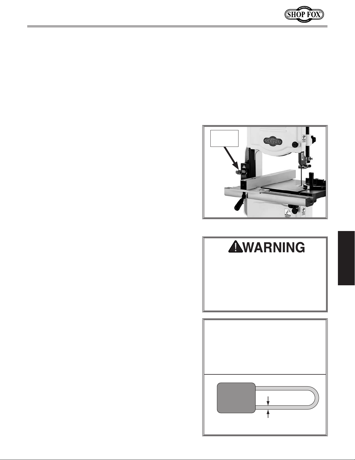
The ON/OFF switch can be disabled and
locked with the provided padlock (see
Figure 34). While the padlock is inserted
through the ON button, the motor
cannot be started, which reduces the
risk of accidental startup by children of
unauthorized users.
Padlock
Installed
Adjusts the table tilt, if necessary, to the correct
3.
angle of the desired cut.
4. Loosens the guide post lock knob, adjusts the blade
guide height to between 1⁄4" and 1" from the top
of the workpiece using the guide post elevation
handwheel, then tightens the guide post lock knob.
Checks to make sure the workpiece can safely pass
5.
all the way through the blade without interference
from other objects.
Puts on safety glasses and a respirator.
6.
7. Starts the dust collector and bandsaw, and waits for
the blade to come to full speed.
Holds the workpiece firmly and flatly against both
8.
the table and fence, and then pushes the workpiece
into the blade at a steady and controlled rate until
the workpiece moves completely beyond the blade.
Figure 34. Padlock installed in the switch.
OPERATIONS
Children or untrained people can
be killed or seriously injured by this
machine. If the machine is accessible to
children or other people, always disable
and lock the switch before leaving the
machine unattended. Place the key in a
well-hidden or secure location.
NOTICE
The switch can only be disabled if
the installed padlock shaft meets the
minimum diameter shown below;
otherwise, the shaft may be too small
to properly disable the switch.
The operator is very careful to keep fingers away
from the blade and uses a push stick to feed narrow
workpieces.
Stops the bandsaw.
9.
-27-
Minimum Shaft Diameter = 0.192" – 0.2"
(4.8 – 5mm)
Page 32
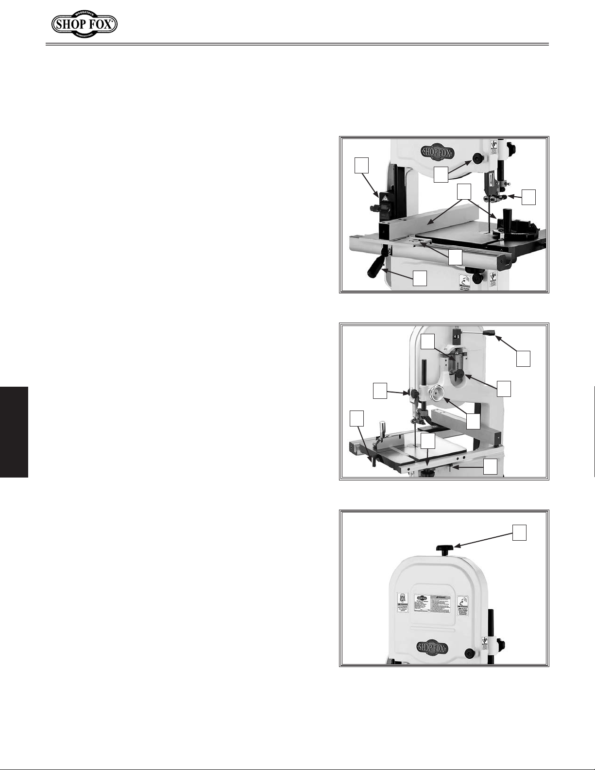
Basic Controls
Refer to Figures 35–37 and the descriptions below to
better understand the basic controls and components of
this bandsaw.
A. ON/OFF Buttons: Turns the motor ON and OFF.
Model W1706 (Mfg. Since 3/13)
B. Upper Wheel Cover Knob: Enables access to the
upper wheel compartment.
C. Fence and Miter Gauge: Allows for controlled
cutting at various angles.
D. Upper Blade Guide Assembly: Supports the sides
and back of the blade when cutting. The lower guide
assembly underneath the table is similar.
E. Fence Lock Lever: Locks the fence to the front rail.
F. Fence Pointer & Scale: Displays the fence position
relative to the blade.
G. Blade Tension Scale: Indicates the approximate
tension for each blade width. Rotate the blade
tension knob on top of the bandsaw to adjust the
indicator block inside the aluminum housing of the
scale and align it with the appropriate mark on the
scale for the blade width.
H. Blade Tension Quick Release Lever: Quickly
releases or engages full blade tension.
OPERATIONS
I. Blade Tracking Knob: Adjusts the tilt of the upper
wheel for proper blade tracking.
A
B
E
Figure 35. Front Controls
G
N
M
L
Figure 36. Rear controls.
C
F
J
K
D
H
I
J. Guide Post Handwheel: Adjusts the height of the
guide post and blade guide assembly above the
workpiece.
K. Positive Stop: Allows the table to be quickly
returned to 0° after tilting to the right.
L. Trunnion Lock Knob (1 of 2): Secure the table tilt
position.
M. Table Slot Locking Pin: Keeps the table on each side
of the slot even.
N. Guide Post Lock Knob: Secures the guide post in
position.
O. Blade Tension Knob: Adjusts the blade tension.
-28-
O
Figure 37. Blade tension knob.
Page 33
Model W1706 (Mfg. Since 3/13)
Cutting Overview
The Model W1706 is capable of performing the following
cuts:
• Miters • Compound Angles
• Angles • Simple/Complex Curves
• Resawing • Duplicate Parts
• Ripping • Circles
• Crosscutting • Beveled Curves
Workpiece Inspection
Some wood workpieces are not safe to cut or may require
modification before they are safe to cut.
Before cutting wood, get in the habit of inspecting all
workpieces for the following:
• Material Type: This machine is intended for
cutting natural and man-made wood products, and
laminate-covered wood products. Cutting drywall or
cementitious backer board creates extremely fine
dust, which may reduce the life of the bearings. This
machine is NOT designed to cut metal, glass, stone,
tile, etc.
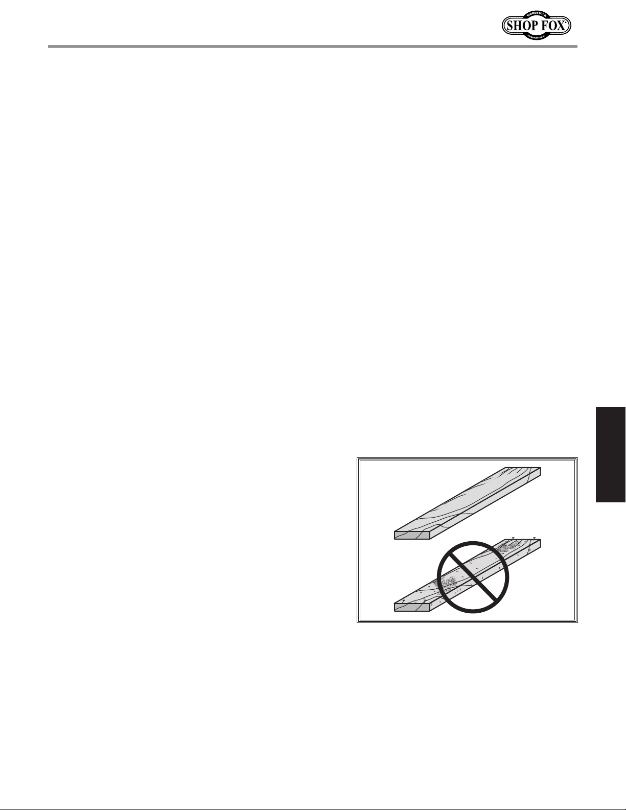
• Foreign Objects (Figure 38): Nails, staples, dirt,
rocks and other foreign objects are often embedded
in wood. While cutting, these objects can become
dislodged and hit the operator or break the blade,
which might then fly apart. Always visually inspect
your workpiece for these items. If they can't be
removed, DO NOT cut the workpiece.
• Large/Loose Knots: Loose knots can become
dislodged during the cutting operation. Large knots
can cause blade damage. Choose workpieces that do
not have large/loose knots or plan ahead to avoid
cutting through them.
OPERATIONS
Figure 38. Selecting the board without
embedded foreign materials.
-29-
Page 34
• Wet or "Green" Stock: Cutting wood with a moisture
content over 20% causes unnecessary wear on the
blade and yields poor results.
• Excessive Warping: Workpieces with excessive
cupping, bowing, or twisting are dangerous to
cut because they are unstable and can move
unpredictably when being cut. DO NOT cut
excessively warped wood.
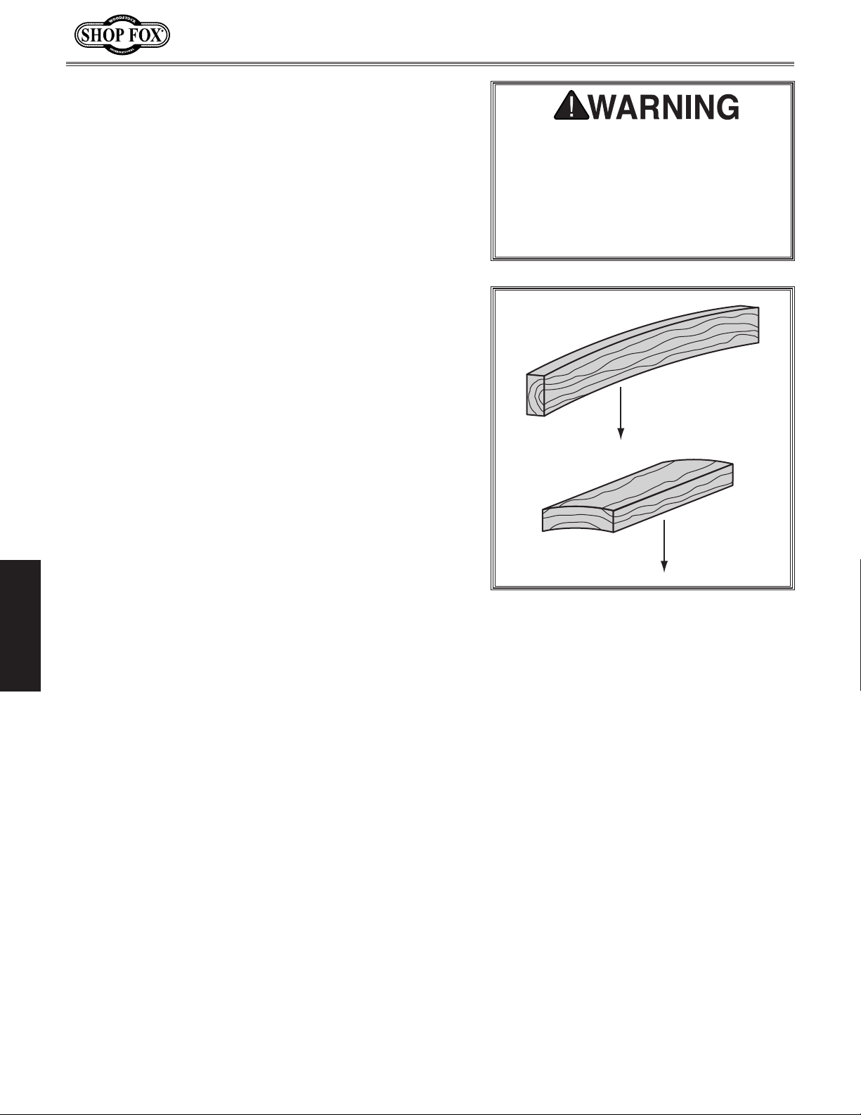
• Minor Warping: Workpieces with slight cupping
can be safely supported if the cupped side faces
the table or fence, as shown in
contrary, a workpiece supported on the bowed side
will rock during a cut, leading to loss of control.
Figure 39. On the
Basic Cutting Tips
Here are some basic tips to follow when operating the
bandsaw:
Model W1706 (Mfg. Since 3/13)
Because of the unpredictable nature
of cutting warped stock, use extreme
caution. The difference between
acceptable and unacceptable warped
stock varies from machine to machine.
If you are in doubt, square-up the
stock first or do not cut it.
Cut with
this side down
• Keep the upper blade guide assembly adjusted to
within 1" of the workpiece.
• Use the correct blade for the operation.
• Replace, sharpen, and clean blades as necessary.
Make adjustments periodically to keep the saw
running in top condition.
• Use light and even pressure while cutting. Light
OPERATIONS
contact with the blade makes it easier to follow
lines and prevents extra friction, which reduces
blade life.
• Avoid twisting the blade when cutting around tight
corners. Allow the blade to saw around the corners.
• Do not back the workpiece away from the blade
while the saw is running.
Cut with
this side down
Figure 39. Cutting workpieces with minor
warping.
-30-
Page 35
Model W1706 (Mfg. Since 3/13)
Table Tilt
The table tilts 45° to the right and 10° to the left for a
wide range of cutting options.
To tilt the table, do these steps:
1. DISCONNECT BANDSAW FROM POWER!
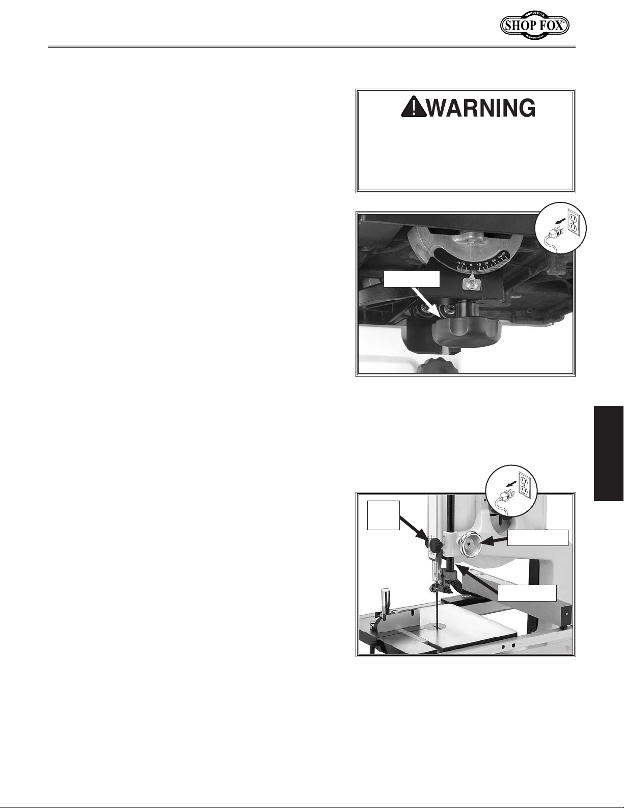
2. Loosen the two trunnion lock knobs underneath the
table (see Figure 40), then use the tilt scale on
the front of the trunnion to bring the table to the
desired angle.
Note: When tilting the table to the left, the
positive stop must be lowered or removed.
Remember to properly re-adjust it after returning
the table from a left-hand tilt (refer to Page 18).
Tighten both trunnion lock knobs to secure the table
3.
in place.
Adjusting Guide Post
The guide post (see Figure 41) moves the blade guide
assembly up or down. To cut accurately and safely, the
bottom of the blade guide assembly must be no more
than 1" above the workpiece during cutting operations—
this positioning provides the greatest blade support and
minimizes the length of moving blade that is exposed to
the operator.
If the bandsaw should unexpectedly
start when making adjustments, severe
personal injury could result. ALWAYS
disconnect the bandsaw from power
before making any adjustments.
Lock Knob
Figure 40. Location of trunnion lock knob
(1 of 2).
OPERATIONS
To adjust the guide post, do these steps:
1. DISCONNECT BANDSAW FROM POWER!
2. Make sure that the blade tension, blade tracking,
support bearings, and blade guides are adjusted
correctly.
Loosen the guide post lock knob shown in Figure 41.
3.
Rotate the guide post handwheel to properly position
4.
the blade guide assembly above the workpiece, then
re-tighten the lock knob to secure the setting.
-31-
Lock
Knob
Handwheel
Guide Post
Figure 41. Guide post controls.
Page 36
Ripping
Ripping is the process of cutting with the grain of the
wood stock. For plywood and other processed wood,
ripping simply means cutting down the length of the
workpiece. For ripping, a wider blade is better. In most
ripping applications, a standard raker tooth style will be
sufficient (refer to
To make a rip cut, do these steps:
Adjust the fence to match the width of the cut on
1.
your workpiece and lock the fence in place.
Adjust the blade guide assembly to the correct
2.
height.
After all safety precautions have been met, turn
3.
the bandsaw ON and wait for the blade to reach full
speed.
Blade Information on Page 37).
Model W1706 (Mfg. Since 3/13)
NEVER place fingers or hands in the
line of cut. In the event that something
unexpected happens, your hands or
fingers may be pulled into the blade.
ALWAYS use a push stick when ripping
narrow pieces. Failure to follow these
warnings may result in serious personal
injury!
Slowly feed the workpiece into the blade and
4.
continue with the cut until the blade is completely
through the workpiece.
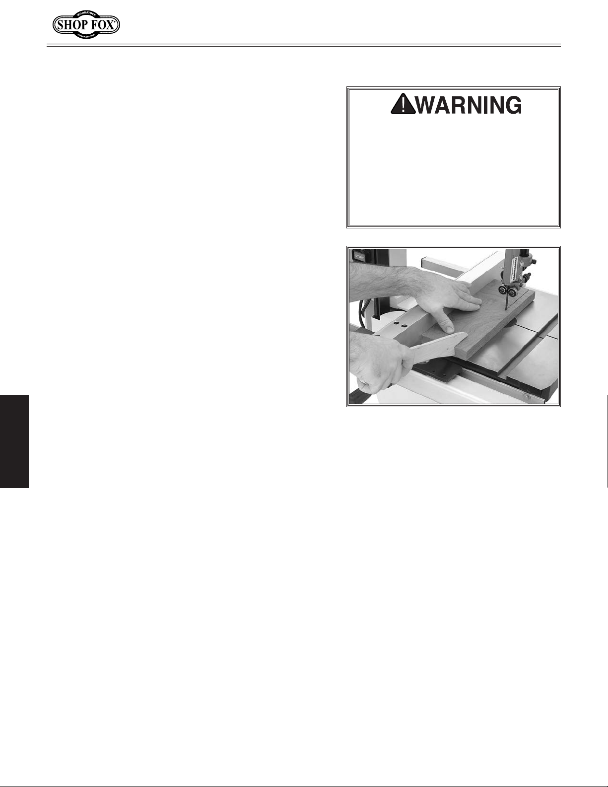
Figure 42 shows a typical ripping operation.
Note: If you are cutting narrow pieces, use a push
stick to protect your fingers.
OPERATIONS
Figure 42. Example of ripping.
-32-
Page 37
Model W1706 (Mfg. Since 3/13)
Crosscutting
Crosscutting is the process of cutting across the grain
of wood. For plywood and other processed wood,
crosscutting simply means cutting across the width of the
material.
To make a 90˚ crosscut, do these steps:
Mark the workpiece on the edge where you want to
1.
begin the cut.
Adjust the blade guide assembly to the correct
2.
height and make sure the miter gauge is set to 0°
(or other angle for angled cuts).
Move the fence out of the way. Place the workpiece
3.
evenly against the miter gauge.
Hold the workpiece against the miter gauge and line
4.
up the mark with the blade.
After all safety precautions have been met, turn
5.
the bandsaw ON and wait for the blade to reach full
speed.
Slowly feed the workpiece into the blade and
6.
continue the cut until the blade is all the way
through the workpiece.
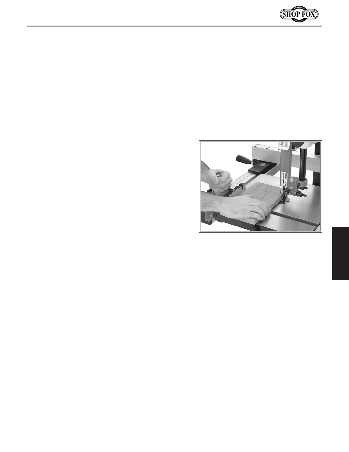
Figure 43 shows a typical crosscutting operation.
OPERATIONS
Figure 43. Making a 90° crosscut.
-33-
Page 38
Resawing
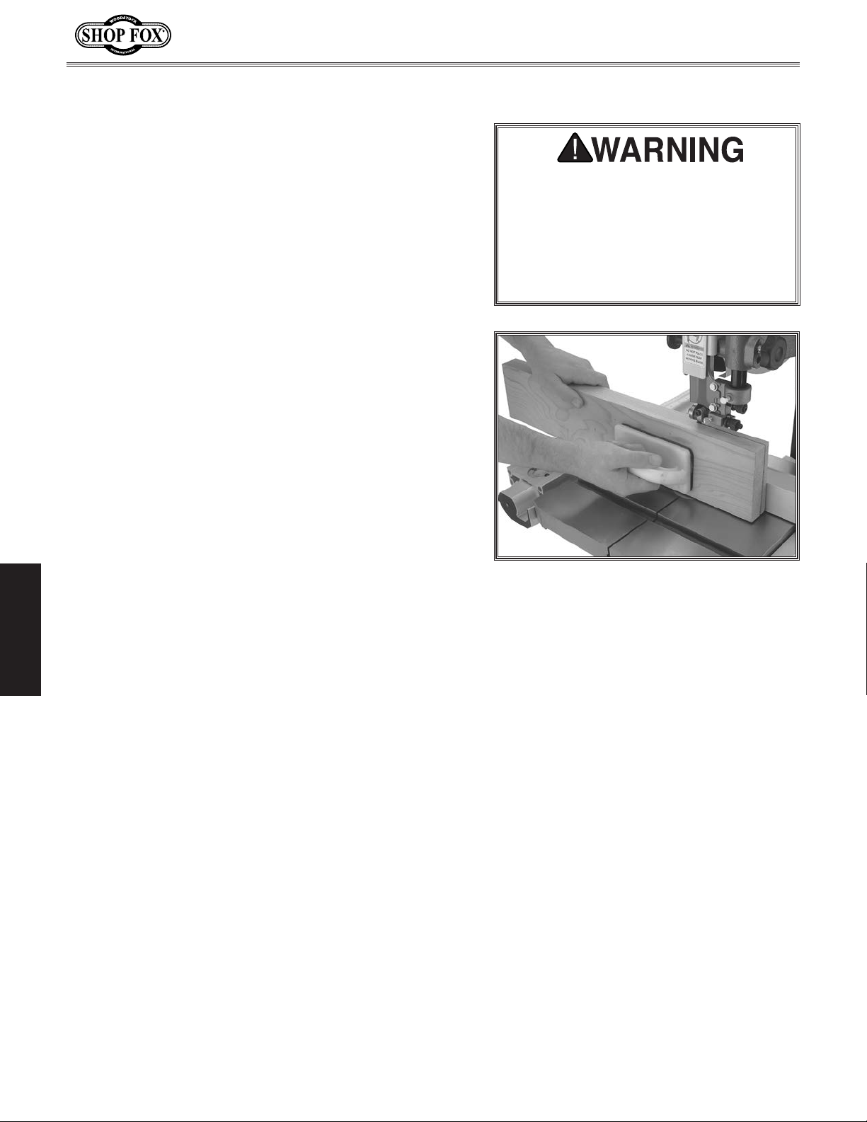
Resawing (see Figure 44 for an example) is the process
of cutting a board into two or more thinner boards. The
maximum board width that can be resawn is limited by
the maximum cutting height of the bandsaw. Maximum
cutting height for this bandsaw is 6".
The Model W1706 is capable of resawing, provided the
saw is set up properly. Use common sense when resawing.
Attempting to resaw too wide or too dense of a board
may put excessive strain on the blade and cause it to
break.
One of the most important considerations when resawing
is blade selection. Use the widest blade possible when
resawing—a wide blade cuts straighter and is less prone to
blade lead (refer to
information). In most applications, a hook or a skip tooth
style will be desirable.
Blade Lead on Page 46 for additional
Model W1706 (Mfg. Since 3/13)
When resawing thin pieces, a
wandering blade (blade lead) can tear
through the surface of the workpiece,
exposing your hands to the blade
teeth. ALWAYS keep your hands clear
of the blade by using push blocks and
push sticks when resawing.
Also, since most resawn lumber will be planed smooth,
you should choose blades with fewer teeth-per-inch
(from 3 to 6 TPI). While blades with fewer teeth-per-inch
produce rougher cuts, these types of blades offer larger
gullet capacities for clearing sawdust.
To resaw a workpiece, do these steps:
1. Verify that the bandsaw is setup properly and that
the table is perpendicular to the blade.
OPERATIONS
Use the widest blade your bandsaw will accept. The
2.
blade must also be sharp and clean.
Set the fence to the desired width of cut and lock it
3.
in place.
Tip: You can also draw a reference line on the edge
of the board, place the board against the fence, line
up the reference line with the blade, then lock the
fence in place.
Support the ends of the board if necessary.
4.
Figure 44. Example of resawing.
5. Turn the bandsaw ON and wait for the blade to reach
full speed.
Keeping even pressure against the fence and table
6.
with the workpiece, slowly feed it into the moving
blade until the blade is completely through the
workpiece.
-34-
Page 39
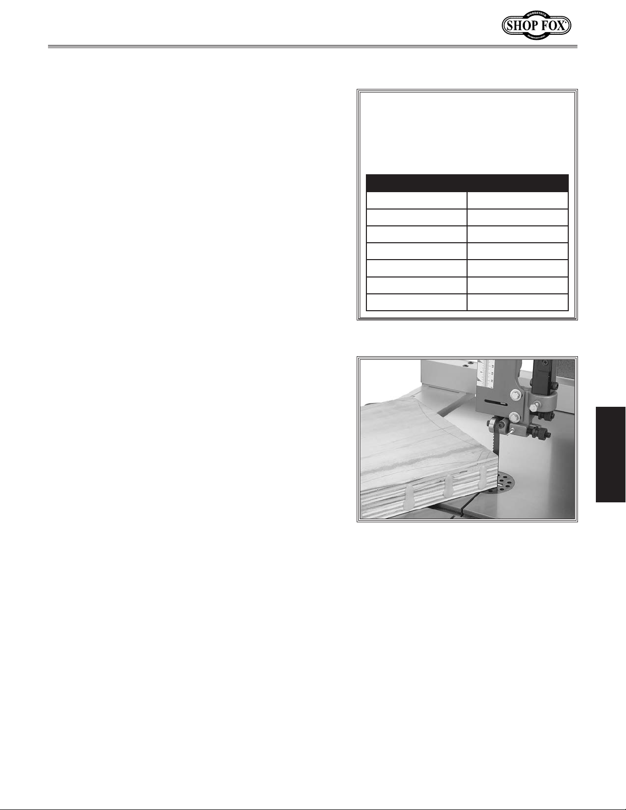
Model W1706 (Mfg. Since 3/13)
Cutting Curves
When cutting curves, simultaneously feed and turn the
stock carefully so that the blade follows the layout line
without twisting. Use either a narrower blade or a blade
with more TPI (teeth per inch), or make more relief cuts,
to avoid having to back the workpiece away from the
blade, especially if the curve is sharp.
NOTICE
The chart below displays blade widths
and the corresponding minimum radii
for those widths.
Always make short cuts first, then proceed to the longer
cuts. Relief cuts will also reduce the chance that the
blade will be pinched or twisted. Relief cuts are cuts
made through the waste portion of the workpiece and
are stopped at the layout line. As you cut along the
layout line, waste wood is released from the workpiece,
alleviating any pressure on the back of the blade. Relief
cuts also make backing the workpiece out easier once the
saw blade has come to a stop, if needed.
Stacked Cuts
One of the benefits of a bandsaw is its ability to cut
multiple copies of a particular shape by stacking a number
of workpieces together (see
Before making stacked cuts, ensure that both the table
and the blade are properly adjusted to 90°. Otherwise,
any error will be compounded.
To complete a stacked cut, do these steps:
Figure 45 for an example).
Width Radius
1
⁄8"
3
⁄16"
1
⁄4"
3
⁄8" 1 1⁄4"
1
⁄2" 2 1⁄2"
5
⁄8" 3 3⁄4"
3
⁄4" 5 1⁄2"
1
⁄8"
3
⁄8"
5
⁄8"
OPERATIONS
Align your pieces from top to bottom to ensure that
1.
each piece has adequate scrap to provide a clean,
unhampered cut.
Secure all the pieces together in a manner that
2.
will not interfere with the cutting. Hot glue on the
edges works well, as do brad nails through the waste
portion. (Be careful not to cut into the brads or you
may break the blade!)
On the face of the top piece, lay out the shape you
3.
intend to cut.
Make relief cuts perpendicular to the outline of your
4.
intended shape in areas where changes in blade
direction could strain the woodgrain or cause the
blade kerf to bind.
Cut the stack of pieces as though you were cutting a
5.
single piece. Follow your layout line with the blade
kerf on the waste side of your line.
Figure 45. Example of stacked cutting.
-35-
Page 40
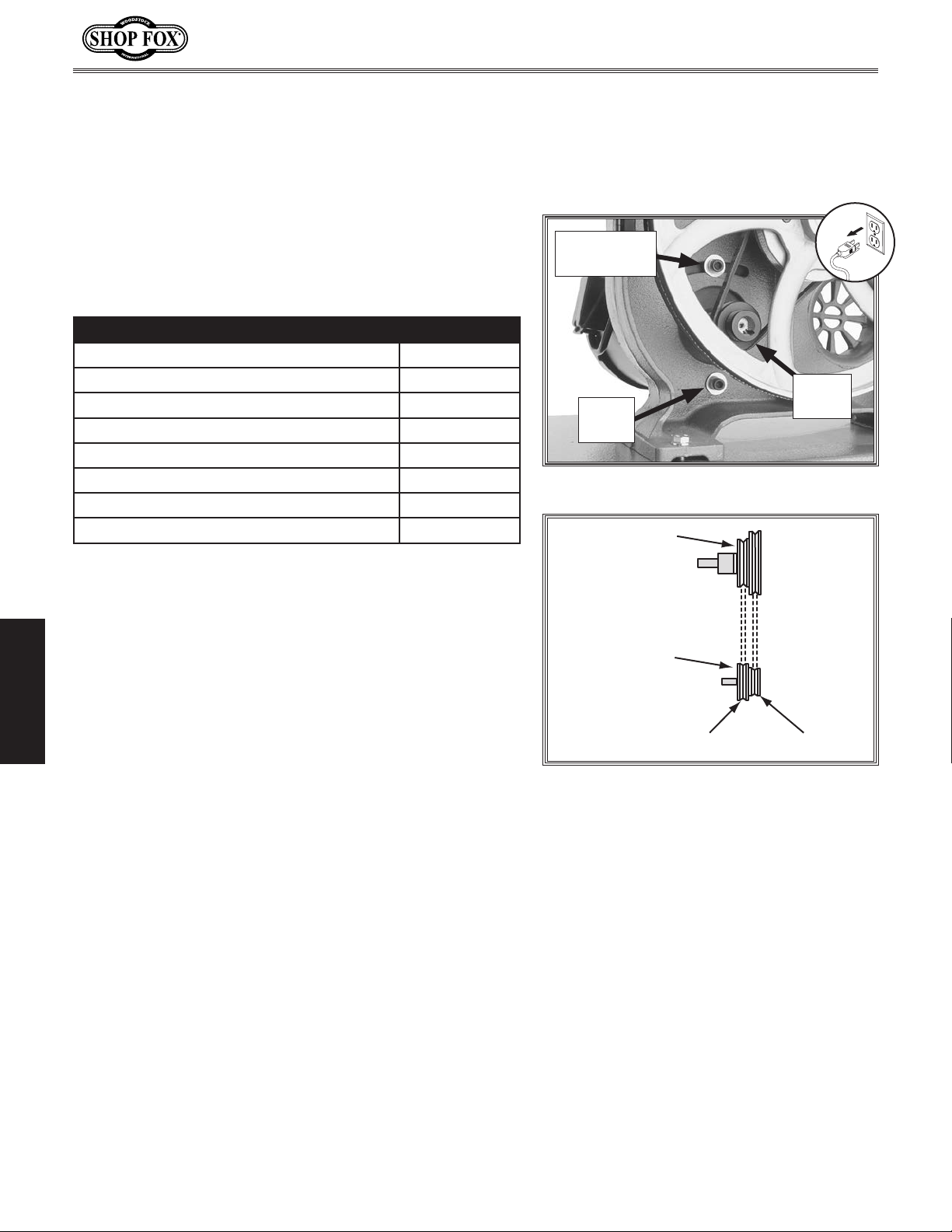
Blade Speed
The Model W1706 offers blade speeds of 1800 and 3100
FPM (Feet Per Minute). For general woodworking and most
cutting operations, we recommend using the 3100 FPM
speed. Keep in mind, the results from different speeds
are related to the type of blade being used. Whenever
determining blade speed, also choose a type of blade that
is related to your operation. Use the chart below as a
general guide to blade speed:
Type of Cutting Operation Blade Speed
Most Species of Wood 3100 FPM
Super Dense Hardwood 180 0 FPM
Fast/Average Feed Rate 3100 FPM
Requires Slow Feed Rate 180 0 FPM
Rough Edges Tolerable 3100 FPM
Requires Smooth Edges 1800 FPM
Quick, Production Cuts 3100 FPM
Detailed, Intricate Cuts 180 0 FPM
Model W1706 (Mfg. Since 3/13)
Adjustment
Bolt
Hinge
Bolt
Figure 46. Blade speed controls.
Wheel Pulley
Motor
Pulley
Speed changes are performed by moving the belt to one
of the two sets of pulleys.
Tools Needed Qty
Socket 12mm w/Extension
To change the blade speed, do these steps:
1. DISCONNECT BANDSAW FROM POWER!
OPERATIONS
2. Open the lower wheel cover, then loosen the motor
mount bolts (adjustment and hinge bolts) shown in
Figure 46.
Move the body of the motor so that the motor
3.
adjustment bolt slides to the right-hand side (facing
bandsaw front) of the adjustment slot.
Place the belt in the wheel pulley and motor pulley
4.
grooves, as illustrated in Figure 47, for your desired
speed.
Move the body of the motor so that the motor
5.
adjustment bolt slides to the left-hand side (facing
bandsaw front) of the adjustment slot.
Hold the motor in position with one hand and tighten
6.
the motor adjustment bolt with the other hand.
....................................1
Motor Pulley
3100 FPM 1800 FPM
Figure 47. Belt positions for selecting the
blade speed.
7. Push the center of the belt with
moderate force.
— If deflection is approximately 3⁄4"
with moderate pressure from your
thumb or finger, then the tension is
correct.
— If the deflection is more than 3⁄4",
repeat
When the belt tension is correct,
8.
tighten the motor hinge bolt and close
the lower wheel cover.
Steps 3–6.
-36-
Page 41
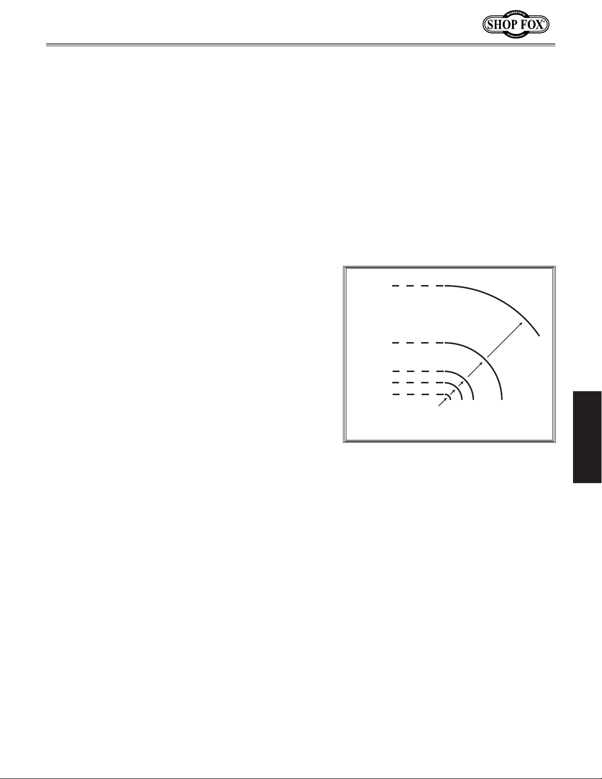
Model W1706 (Mfg. Since 3/13)
Blade Information
Selecting the right blade requires a knowledge of the
various blade characteristics to match the blade with the
particular cutting operation.
Blade Length
Measured by the circumference, blade lengths are usually
unique to the brand of your bandsaw and the distance
between wheels.
blades. Refer to
Blade Width
Measured from the back of the blade to the tip of the
blade tooth (the widest point), blade width is often the
first consideration given to blade selection. Blade width
dictates the largest and smallest curve that can be cut, as
well as how accurately it can cut a straight line.
This saw uses 92 1⁄2" to 93 1⁄2" long
Page 40 for blade replacements.
1
"
2
/
1
This saw uses blades from
⁄8" to 3⁄4" in width. Always pick
the size of blade that best suits your application.
• Curve Cutting: Use the chart in Figure 48 to
determine the correct blade for curve cutting.
Determine the smallest radius curve that will be cut
on your workpiece and use the corresponding blade
width.
• Straight Cutting: Use the largest width blade that
you own. Large blades excel at cutting straight lines
and are less prone to wander.
1
"
2
2
3
"
8
/
1
"
4
/
Blade Width
3
"
16
/
1
"
8
/
1
1
5
"
8
/
3
"
8
/
1
"
8
/
/
"
4
/
Cutting Radius
Figure 48. Blade width in relation to
cutting radius.
OPERATIONS
-37-
Page 42
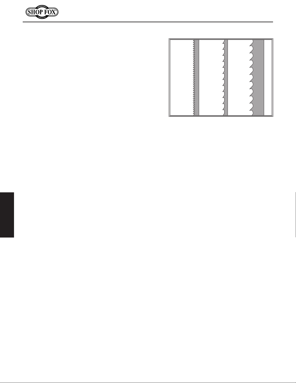
Tooth Style
Figure 49 illustrates the three main tooth styles:
• Raker: Considered to be the standard because the
tooth size and shape are the same as the tooth
gullet. The teeth on raker blades usually are very
numerous, have no angle, and produce cuts by
scraping the material. As a result, smooth cuts can
be achieved without cutting fast or generating more
heat than other types.
• Skip: Similar to a raker blade that is missing every
other tooth. Because of the design, skip toothed
blades have a much larger gullet than raker blades,
and therefore, cut faster and generate less heat.
However, these blades also leave a rougher cut than
raker blades.
• Hook: The teeth have a positive angle (downward)
which makes them dig into the material, and the
gullets are usually rounded for easier waste removal.
These blades are excellent for the tough demands of
resawing and ripping thick material.
Tooth Pitch
Measured as TPI (Teeth Per Inch), tooth pitch determines
the size of the teeth. More teeth per inch (fine pitch)
will cut slower, but smoother; while fewer teeth per inch
(coarse pitch) will cut rougher, but faster. As a general
rule, choose blades that will have at least three teeth
in the material at all times. Use fine-pitched blades on
OPERATIONS
harder woods and coarse-pitched blades on softer woods.
Blade Care
A bandsaw blade is a thin piece of steel that is subjected
to tremendous strain. You can obtain longer use from a
bandsaw blade if you give it fair treatment and always use
the appropriate feed rate for your operation. Be sure to
select blades with the proper width, style, and pitch for
each application. The wrong choice of blades will often
produce unnecessary heat which will shorten the life of
your blade.
A clean blade will perform much better than a dirty
blade. Dirty or gummed up blades pass through the
cutting material with much more resistance than clean
blades. This extra resistance also causes unnecessary
heat. Resin/pitch cleaners are excellent for cleaning dirty
blades.
Model W1706 (Mfg. Since 3/13)
Raker Skip Hook
Figure 49. Three main tooth styles.
Blade Breakage
Many conditions may cause a bandsaw
blade to break. Blade breakage is
unavoidable, in some cases, since it is
the natural result of the peculiar stresses
that bandsaw blades are subjected to.
Blade breakage is also due to avoidable
circumstances. Avoidable breakage is most
often the result of poor care or judgement
on the part of the operator when mounting
or adjusting the blade or support guides.
The most common causes of blade
breakage are:
• Faulty alignment/adjustment of the
guides.
• Forcing/twisting a wide blade around
a short radius.
• Feeding the workpiece too fast.
• Dull teeth or damaged tooth set.
• Over-tensioned blade.
• Top blade guide assembly set too high
above the workpiece.
• Using a blade with a lumpy or
improperly finished braze or weld.
• Continuously running the bandsaw
when not in use.
• Leaving blade tensioned when not in
use.
• Using the wrong TPI for the workpiece
thickness. (The general rule of thumb
is three teeth in the workpiece at all
times.)
-38-
Page 43
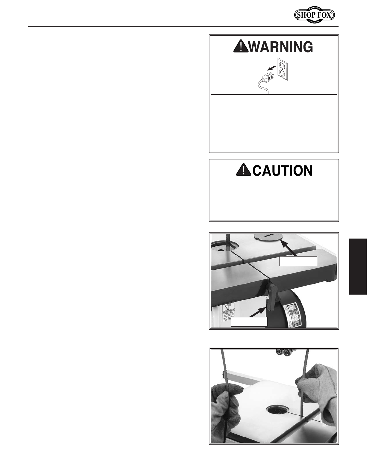
Model W1706 (Mfg. Since 3/13)
Blade Changes
To change the blade, do these steps:
1. DISCONNECT BANDSAW FROM POWER!
2. Put on heavy leather gloves and safety glasses.
3. Release the blade tension by moving the tension
quick release lever all the way left.
Remove the table insert and the table locking pin
4.
Figure 50).
(see
Adjust the upper and lower guide bearings as far
5.
away as possible from the blade.
Open the both wheel covers and slide the blade off
6.
of both wheels.
Slide the blade through the slot in the table.
7.
8. Slide the new blade through the table slot, ensuring
that the teeth are pointing forward and down toward
the table, as shown in
Note: If the teeth will not point downward in any
orientation, the blade is inside-out. Remove the
blade and twist it right side-out.
Slip the blade through the guides, and mount it on
9.
the upper and lower wheels.
Figure 51.
If the bandsaw should unexpectedly
start up when the wheel covers are
open or when changing the blade,
entanglement or amputation injuries
could result. ALWAYS disconnect the
bandsaw from power before opening
the wheel covers.
Bandsaw blades are sharp and can spring
open when uncoiled, which could cause
deep punctures or lacerations. ALWAYS
wear heavy leather gloves and safety
glasses when handling bandsaw blades.
OPERATIONS
Table Insert
Adjust the blade tension as described on Page 17.
10.
Adjust the blade tracking if needed (refer to
11.
Page 14).
Align the upper and lower support bearings (refer
12.
Page 22), then adjust the blade guide bearings
to
(refer to
Replace the table insert and table locking pin.
13.
Close the wheel covers.
14.
Page 24).
Locking Pin
Figure 50. Table insert and locking pin.
Figure 51. Changing the blade.
-39-
Page 44
Model W1706 (Mfg. Since 3/13)
ACCESSORIES
Bandsaw Accessories
The following Bandsaw accessories may be available through your local Woodstock International Inc.
Dealer. If you do not have a dealer in your area, these products are also available through online
dealers. Please call or e-mail Woodstock International Inc. Customer Service to get a current listing of
dealers at: 1-800-840-8420 or at [email protected].
®
The Steelex
W1706 feature hardened teeth and a flexible back to provide extra
cutting sharpness and durability for all woodcutting applications. We
tested these against some of the highest-priced carbon blades on
the market and could tell no difference in performance. These great
blades are priced within reach of any shop. Available in raker and hook
styles with various TPI, and from
High-Carbon Steel Replacement Blades for the Model
1
⁄8" to 3⁄4" in width.
The D2260A SHOP FOX Adjustable Mobile Base supports your
bandsaw so you can move it easily and lock it in position. All
FOX Adjustable Mobile Bases are the first mobile bases designed
strong enough to move heavy machines on a continual basis. These
mobile bases are adjustable to fit a variety of machines and can be
leveled without the use of shims or tools.
The SHOP FOX D3348 6" Extension Block Kit allows you to increase
the cutting capacity of the W1706 Bandsaw to 12". This kit contains
OPERATIONS
a 105" blade, a 6" spacer block, the extended blade guards, a blade
post extension, and all the mounting hardware. This is an excellent
and easy upgrade to your bandsaw.
The SHOP FOX Heavy-Duty Roller Stands & Roller Tables make
using your bandsaw safer and easier. All models feature convenient
hand knobs for fast height adjustment and offer rigid steel construction. These stands are invaluable for supporting work on bandsaws to
reduce blade bend and pinch on long boards.
SHOP
-40-
Page 45
Model W1706 (Mfg. Since 3/13)
MAINTENANCE
General
Regular periodic maintenance on your machine will
ensure its optimum performance. Make a habit of
inspecting your machine each time you use it.
On a daily basis, check for the following conditions
and repair or replace when necessary:
• Loose mounting bolts.
• Worn switch.
• Worn or damaged cords and plugs.
• Damaged or worn V-belt.
• Damaged or worn blade support and guide bearings.
• Damaged or glazed wheel rubber tires.
• Any other condition that could hamper the safe
operation of this machine.
MAKE SURE that your machine is
unplugged during all maintenance procedures! If this warning is ignored, serious personal injury may occur.
Lubrication
Cleaning
Frequently blow-off sawdust with compressed air. This is
especially important for the internal working parts and
motor. Dust build-up around the motor is a sure way to
decrease its life span. Additionally, open the wheel covers
and clean away any sawdust and built-up grime.
Protecting Table
The table can be kept rust-free with regular applications
of products like SLIPIT
want to consider products like Boeshield T-9™.
®
. For long term storage you may
The sealed and pre-lubricated ball bearings
on this bandsaw require no lubrication for
the life of the bearings. All bearings are
standard sizes, and replacements can be
purchased from our parts department or a
bearing supply store.
As for other items on this machine, such as
adjustment controls, wipe off any sawdust
with a clean cloth, towel or dry paint
brush, then apply a small amount of light
machine oil.
Take care oil does not get on the pulleys
or belt that would cause belt deterioration
and slippage and a reduction in power
efficiency.
MAINTENANCE
-41-
Page 46
SERVICE
General
This section covers the most common service adjustments
or procedures that may need to be made during the life
of your machine.
If you require additional machine service not included
in this section, please contact Woodstock International
Technical Support at (360) 734-3482 or send e-mail to:
[email protected].
Model W1706 (Mfg. Since 3/13)
Redressing Rubber Tires
As the bandsaw ages, the rubber tires may need to
be redressed if they become hardened or glazed over.
Redressing the rubber tires improves blade tracking and
reduces vibration/blade lead.
If the rubber tires become too worn, then blade tracking
will become extremely difficult. At that point, redressing
will no longer be effective and the tires must be
replaced.
To redress the rubber tires, do these steps:
DISCONNECT BANDSAW FROM POWER!
1.
2. Put on heavy leather gloves, then remove the blade.
Clean any built-up sawdust from the rubber tires.
3.
4. Hold 100 grit sandpaper against the rubber tire and
rotate the wheel by hand. Only redress the rubber
enough to expose a fresh rubber surface.
MAKE SURE that your machine is
unplugged during all service procedures! If this warning is ignored, serious personal injury may occur.
Re-install the blade, then check blade tension (refer
6.
to Page 17) and tracking (refer to Page 14).
SERVICE
-42-
Page 47
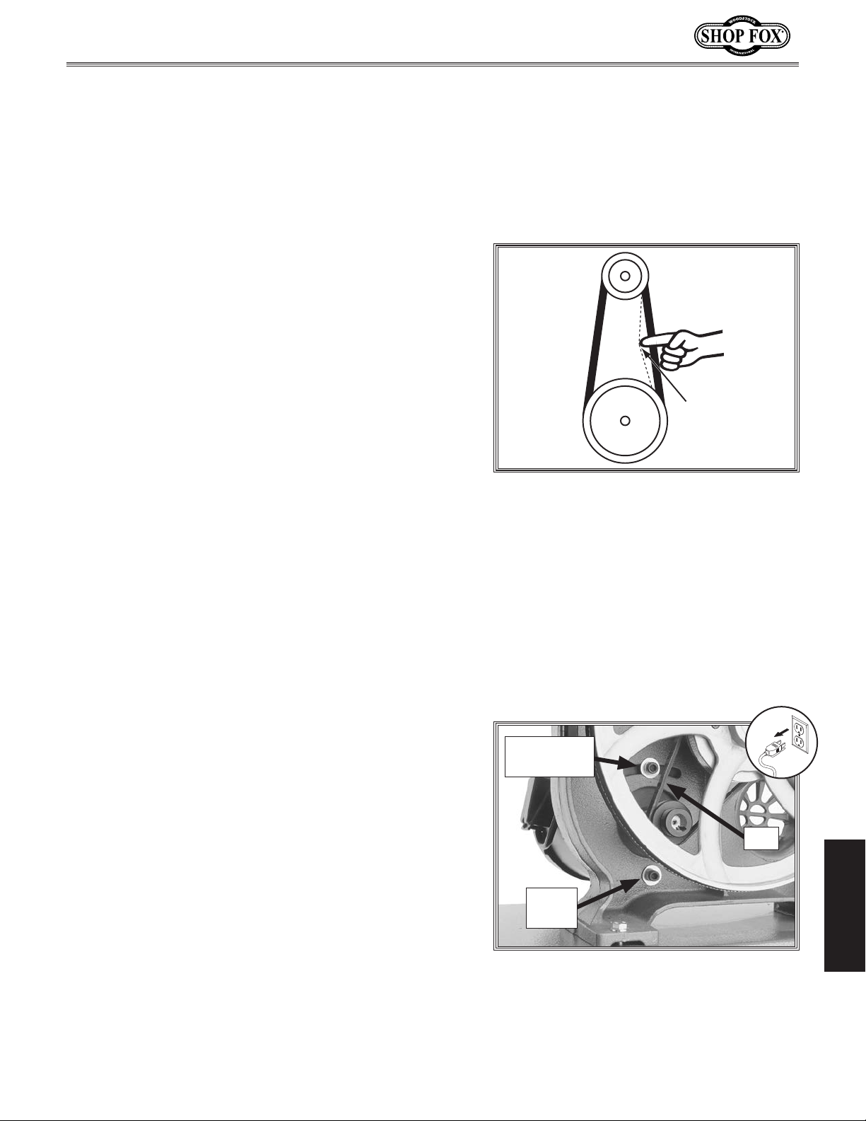
Model W1706 (Mfg. Since 3/13)
Belt Service
To ensure optimum power transmission from the motor to
the blade, the belt must be in good condition and operate
under proper tension. The belt should be checked for
cracks, fraying, and wear. Belt tension should be checked
at least every 3 months—more often if the bandsaw is
used daily.
Checking Belt
1. DISCONNECT BANDSAW FROM POWER!
2. Open the lower wheel cover.
Note the condition of the belt. If the belt is cracked,
3.
frayed, or glazed, it should be replaced.
Press the belt with moderate pressure midway
4.
between the pulleys. The deflection should be
approximately
— If the deflection is not approximately 1⁄4",
continue with the next procedure to properly
tension the belt.
1
⁄4", as illustrated in Figure 52.
Adjusting Belt Tension
Tools Needed Qty
Socket 12mm w/Extension
To tension the belt, do these steps:
....................................1
Pulley
1
⁄4"
Pulley
Figure 52. Testing for proper belt tension.
Deflection
1. DISCONNECT BANDSAW FROM POWER!
2. Open the lower wheel cover and loosen the motor
mount bolts (adjustment and hinge) shown in
Figure 53.
Move the motor so that the motor adjustment bolt
4.
slides to the left-hand side (facing bandsaw front) of
the adjustment slot.
Hold the motor in position with one hand and tighten
5.
the motor adjustment bolt with the other hand.
Press the center of the belt. If deflection is
6.
approximately 1⁄4" with moderate pressure from your
thumb or finger, then the tension is correct. If the
deflection is more than
When the belt tension is correct, tighten the motor
7.
hinge bolt and close the lower wheel cover.
1
⁄4", repeat Steps 4-6.
-43-
Adjustment
Bolt
Belt
SERVICE
Hinge
Bolt
Figure 53. Belt tensioning controls.
Page 48

Replacing Belt
Tools Needed Qty
Socket 12mm w/Extension
Wrench or Socket 13mm
To replace the belt, do these steps:
1. DISCONNECT BANDSAW FROM POWER!
2. Open both wheel covers, remove the bandsaw
blade, and loosen the motor mount bolts shown in
Figure 54 on the previous page.
Move the body of the motor so that the motor
3.
adjustment bolt slides to the right-hand side (facing
bandsaw front) of the adjustment slot and pull the
belt off of the motor pulley.
Unthread the lower wheel mount bolt shown in
4.
Figure 55, then slide the lower wheel off of the
bearing shaft.
....................................1
.......................................1
Model W1706 (Mfg. Since 3/13)
Note: The wheel mount bolt is a left-hand bolt and
unthreads clockwise.
Slip the old belt off of the wheel pulley and install
5.
the new belt in its place.
Position the belt on the pulleys for the desired blade
6.
speed.
Slide the lower wheel back onto the bearing shaft
7.
and replace/tighten the wheel mount bolt.
Move the body of the motor so that the motor
8.
adjustment bolt slides to the left-hand side (facing
bandsaw front) of the adjustment slot.
Hold the motor in position and tighten the motor
9.
adjustment bolt with the other hand.
Check and adjust the belt tension as instructed on
10.
the previous page.
When the belt tension is correct, tighten the motor
11.
SERVICE
hinge bolt, re-install the blade, then close both
wheel covers.
Wheel
Mount Bolt
Figure 55. Lower wheel mount bolt.
Make sure that the blade is correctly tensioned
12.
(refer to Page 17) and is tracking properly (refer to
Page 14).
-44-
Page 49
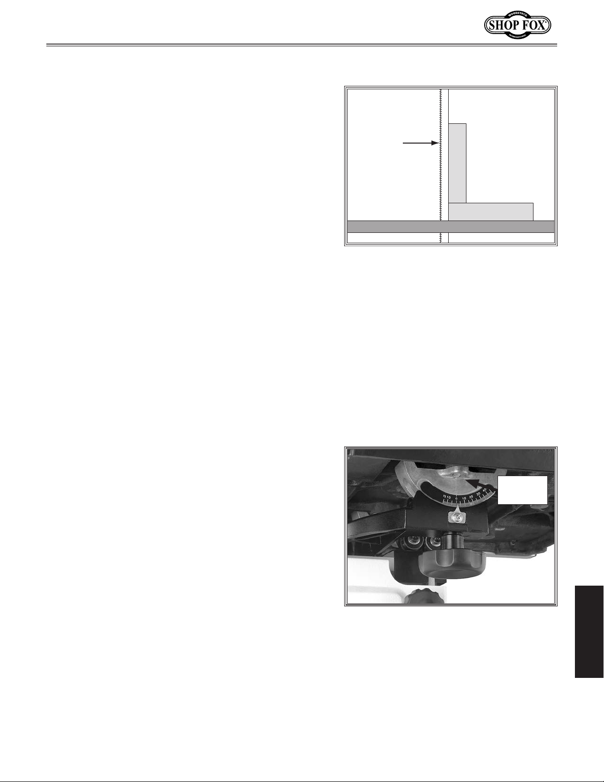
Model W1706 (Mfg. Since 3/13)
Shimming Table
To ensure accuracy when cutting stacked workpieces
or circles, the table should be 90° to the back of the
blade, as illustrated in
perpendicular to the back of the blade, the table will
need to be shimmed.
Needed Qty
Items
Wrench or Socket 10mm
Machinist's Square
Metal Shims
To shim the table, do these steps:
.......................................... As Needed
Figure 56. If the table is not
.......................................1
..............................................1
Blade
Square
Table
1. Make sure that the blade is tracking properly and
that it is correctly tensioned.
DISCONNECT BANDSAW FROM POWER!
2.
3. Bring the table to 0° tilt, then place the machinist's
square flat on the table and against the back of the
blade.
— If there is not a gap between the square and the
blade, no further adjustments need to be made.
— If there is a gap between the square and the
blade, continue with Step 4.
Loosen the six trunnion bolts that secure the
4.
trunnions to the table (see Figure 57).
Place shim stock between the table and the two
5.
trunnions to shim the table in the desired direction.
Another way to shim the table is to add washers
between the table and the trunnion. Electrical
washers are a good choice for this procedure
because they are very thin and will allow for fine
adjustment.
Figure 56. Checking if the table is
perpendicular to the back of the blade.
Trunnion
Bolt
Check, and if necessary, align the table (refer to
6.
Page 19).
SERVICE
Figure 57. Location of trunnion bolt
(1 of 6).
-45-
Page 50
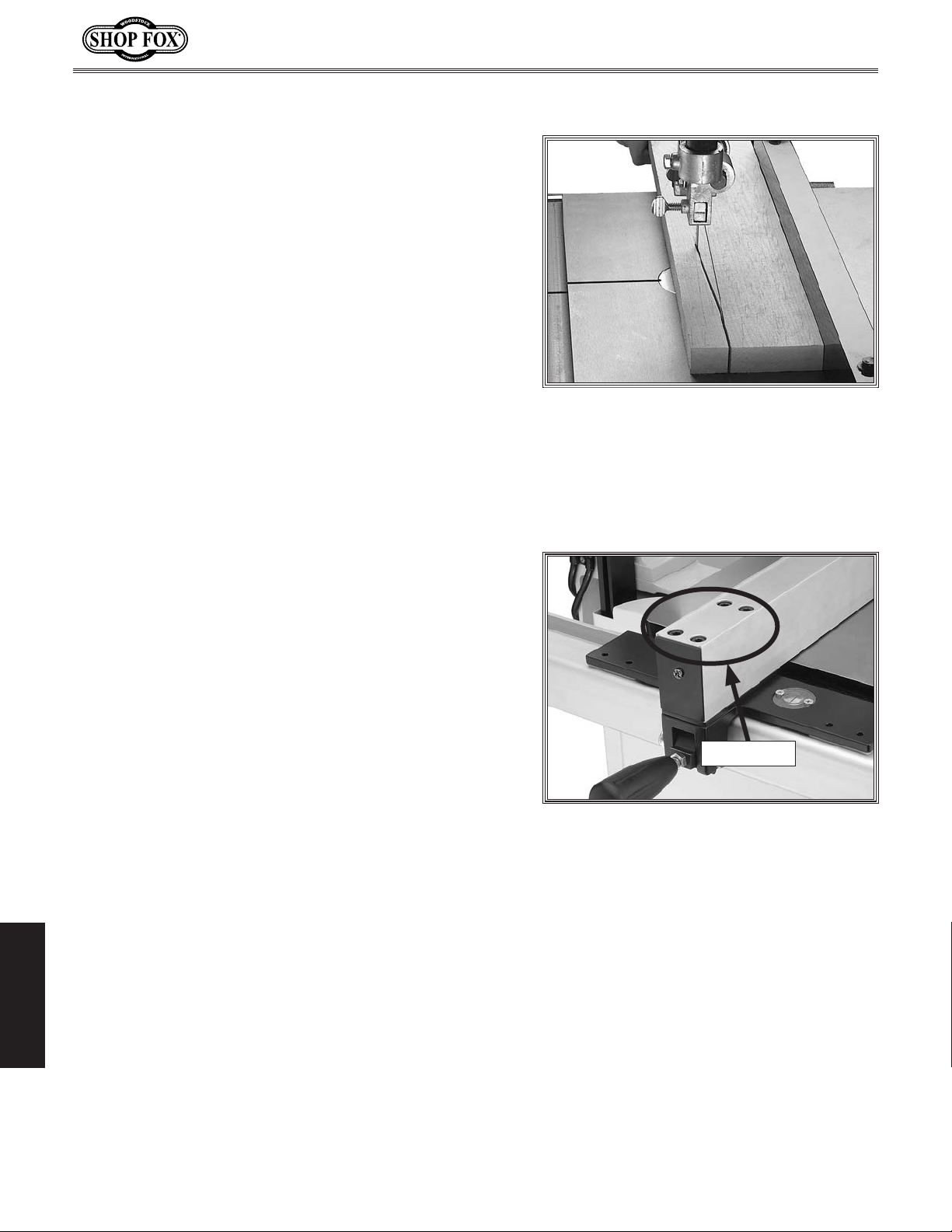
Blade Lead
Bandsaw blades may wander off the cut line when sawing,
as shown in
lead is usually caused by too fast of a feed rate, a dull or
damaged blade, or improper blade tension. If your blade
is sharp/undamaged, properly tensioned and you still have
blade lead, perform the following procedures.
Correcting Blade Lead
1. Use less pressure when feeding the workpiece
through the cut.
Make sure that the fence is parallel to the blade
2.
line, and the miter gauge body is perpendicular to
the blade.
Check for proper blade tension. If the blade tension
3.
is correct and it is not convenient to replace the
blade, compensate for lead by skewing the fence or
shifting the table.
Figure 58—this is called blade lead. Blade
Model W1706 (Mfg. Since 3/13)
Figure 58. Example of blade lead.
Needed Qty
Items
Board
Hex Wrench 5mm
To skew the fence, do these steps:
1.
2.
3.
4.
5.
3
⁄4"T x 3"W x 17"L .......................................1
...............................................1
On the wide face of the board, draw a straight line
parallel to the long edge.
Slide the fence out of the way and cut free-hand
along the line. Stop at the halfway point. Turn the
bandsaw OFF and wait for the blade to stop.
Clamp the board to the bandsaw table without
moving it. Now slide the fence over to the board so
it barely touches one end of the board.
Loosen the four fence alignment cap screws shown in
Figure 59.
Skew the fence left or right so it is parallel to the
edge of the scrap piece.
Cap Screws
Figure 59. Fence alignment cap screws.
While maintaining the skew, tighten the cap screws.
6.
SERVICE
-46-
Page 51
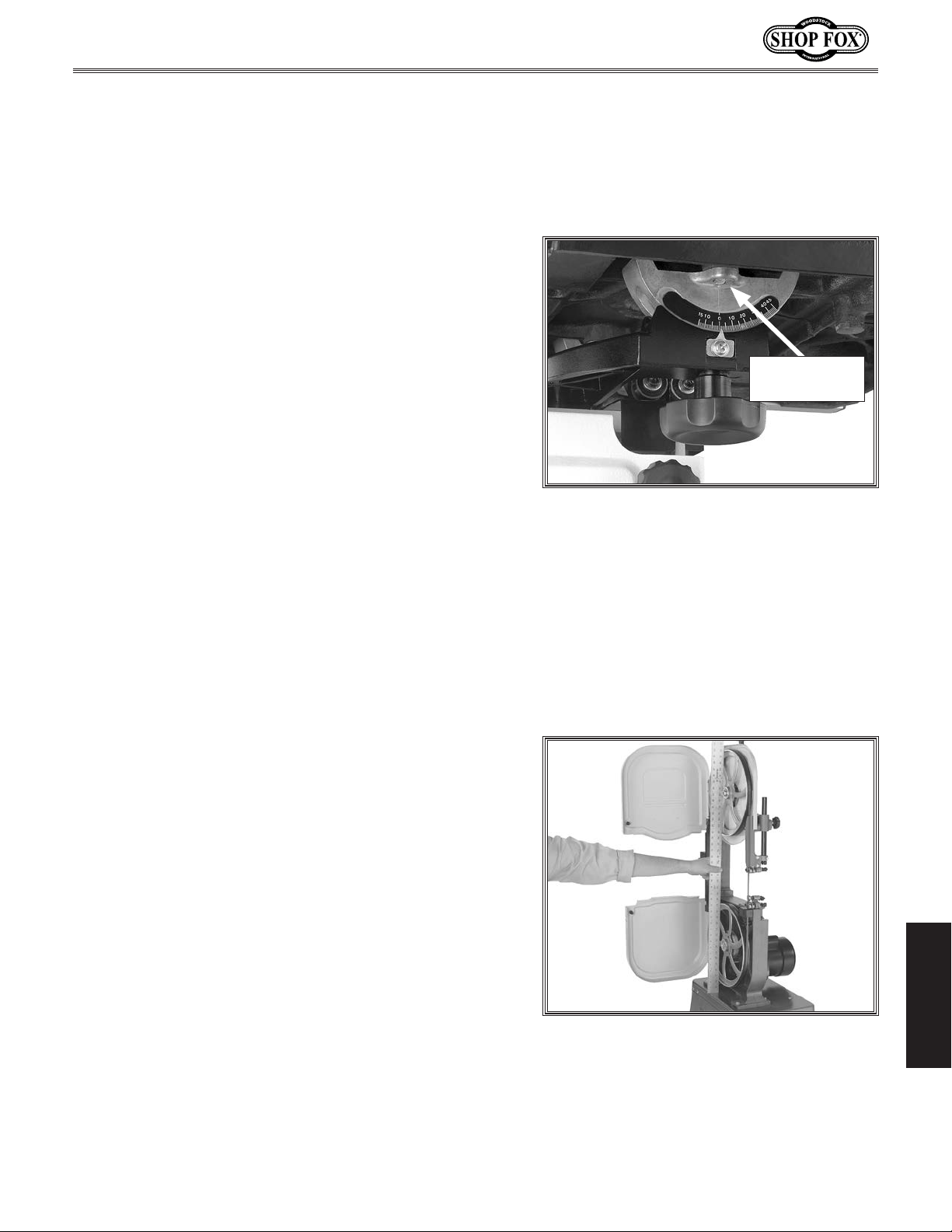
Model W1706 (Mfg. Since 3/13)
Tool Needed Qty
Wrench or Socket 10mm
The skew the table, do these steps:
1. On a scrap piece of wood, mark a line that is
perpendicular to the front edge. Starting where the
line begins, cut the board by pushing it through the
blade with the miter gauge.
Loosen the six trunnion bolts that secure the table
2.
(see Figure 60). Shift the table to compensate
for the difference between the cut edge of the
workpiece and the mark you made in
Note: Keep in mind that as the table alignment is
changed, so is the fence alignment.
Repeat Steps 1–2 until the blade cuts straight when
3.
wood is pushed through with the miter gauge.
Re-tighten the trunnion bolts to secure the setting.
4.
.......................................1
Step 1.
Trunnion Bolt
(1 of 6)
Figure 60. Location of trunnion bolt.
Aligning Wheels
Wheel alignment is one of the easiest ways to ensure
you get optimal performance from your bandsaw. When
wheels are aligned, or coplanar, the bandsaw is more
likely to cut straight without wandering; and vibration,
heat, and blade wear are considerably decreased because
the blade is automatically balanced on the wheel. This is
known as “Coplanar Tracking.”
Tools Needed Qty
Wrench or Socket 10mm
Wrench or Socket 13mm
Wrench or Socket
Straightedge 48"
Fine Ruler
Shim Washers
To verify if the upper and lower wheels are coplanar,
do these steps:
1. DISCONNECT BANDSAW FROM POWER!
2. Remove the table and open both wheel covers.
........................................................1
3
................................................1
........................................ As needed
.......................................1
.......................................1
⁄4" ..........................................1
SERVICE
Figure 61. Checking wheel alignment with
a straightedge.
-47-
Page 52
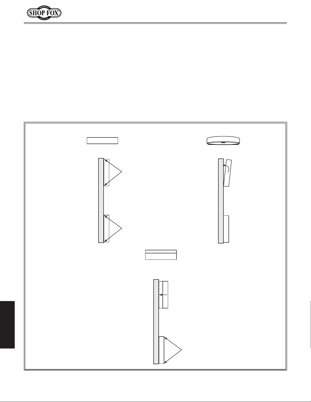
Model W1706 (Mfg. Since 3/13)
3. With the blade installed and properly tensioned, hold a straightedge close to the center of both
wheels. Make sure the straightedge fully extends across the wheels, as shown in Figure 61 on the
previous page.
— If the wheels are coplanar (see Figure 62, "A"), the straightedge will evenly touch the top and
bottom of both wheels.
— If the wheels are not coplanar (see Figure 62, "B"), place the straightedge on the lower wheel
first (ensuring that it touches both the top and bottom rim), then adjust the upper wheel
tracking knob to make the upper wheel coplanar with the lower wheel.
— If the wheels are coplanar (parallel with each other), but the straightedge does not touch the
rims of both wheels (see Figure 62, "C"), then shim the wheels as instructed on the next page.
Straightedge
Contacts Top
And Bottom of
Both Wheels
A
Coplanar
Straightedge
Straightedge Only
Contacts Bottom
Wheel. Top Wheel
Needs to Be Tilted.
C
Parallel, Not
Coplanar
B
Not Coplanar
Solution:
Adjust
Tracking
Knob
Solution:
Shim Wheel
Out
Straightedge
Does Not
Contact Rims
Of Both Wheels
SERVICE
Figure 62. Coplanar conditions.
-48-
Page 53
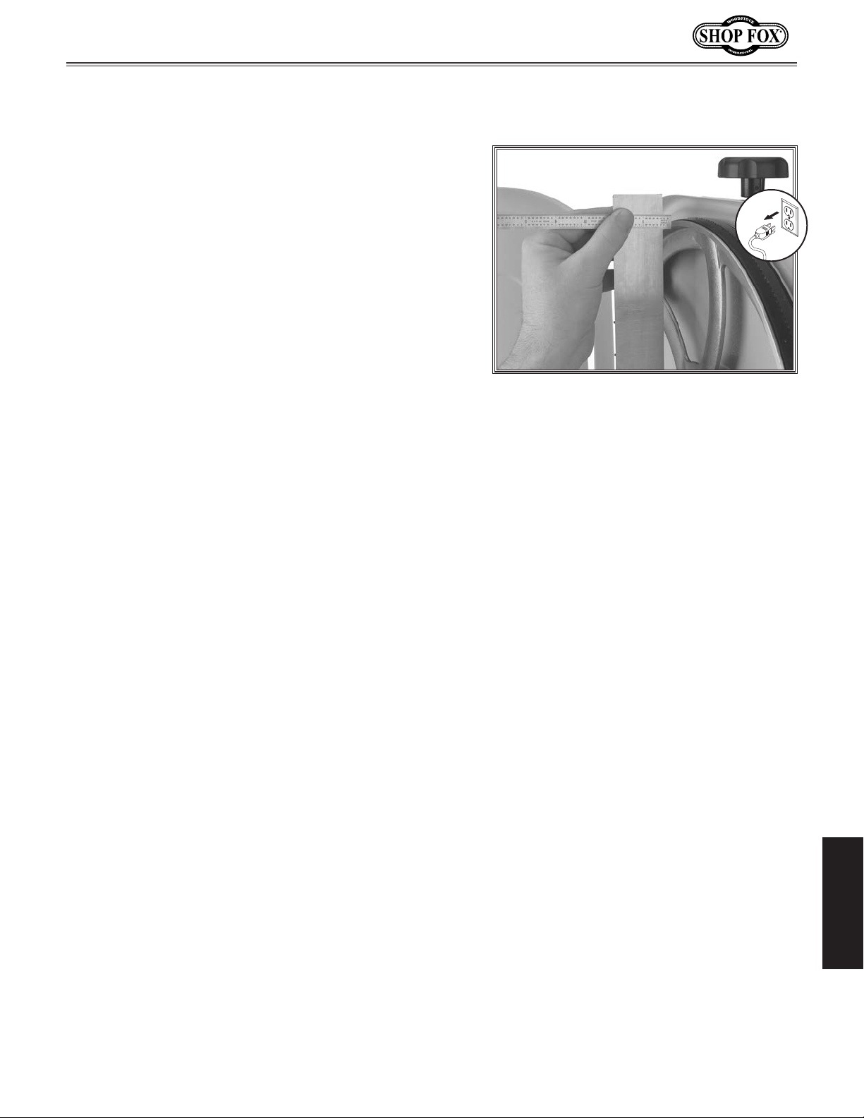
Model W1706 (Mfg. Since 3/13)
Shimming a Wheel
1. DISCONNECT BANDSAW FROM POWER!
2. With a straightedge touching both points of
whichever wheel is forward most, measure the
distance the straightedge is away from the outof-adjustment upper wheel (see
example).
Remove the blade from the saw, then remove the
3.
wheel that needs to be shimmed.
Determine the amount of shim washers necessary to
4.
compensate for the distance measured in
then place them on the wheel shaft.
Figure 63 for an
Step 3,
Replace the wheel and the blade.
5.
Properly tension the blade, then check the wheels
6.
with the straightedge.
Note: Wheel coplanarity changes as the blade is
tightened, so it is best to check the wheel alignment
when the blade is fully tensioned as it would be for
normal operations.
When the wheels are coplanar and even with each
7.
other, place a mark on each wheel where you held
the straightedge. This assures repeated accuracy
every time you adjust your wheels.
Note: When wheels are properly coplanar, the blade
may not be centered on the crown of the wheel, but
it will be balanced.
Secure the wheel covers and re-install the table
8.
before re-connecting the bandsaw to power.
Make sure that the blade is tracking properly (refer
9.
to Page 14).
Figure 63. Measuring the distance the
wheel is out of adjustment.
-49-
SERVICE
Page 54
Model W1706 (Mfg. Since 3/13)
SHOCK HAZARD.
QUALIFIED ELECTRICIAN
WIRE CONNECTIONS.
WIRE/COMPONENT DAMAGE
. The motor wiring shown in these
shocked, wait at least this long before working
Electrical Safety Instructions
These pages are current at the time of printing. However, in the spirit of improvement, we may
make changes to the electrical systems of future machines. Study this diagram carefully. If you notice
differences between your machine and these wiring diagrams, call Woodstock International Technical
Support at (360) 734-3482.
connected to a power source is extremely
dangerous. Touching electrified parts will
result in personal injury including but not
limited to severe burns, electrocution,
or death. Disconnect the power from
the machine before servicing electrical
components!
hazards of electricity, only a qualified
electrician should perform wiring tasks on this
machine. If you are not a qualified electrician,
get help from one before attempting any kind
of wiring job.
tight to prevent wires from loosening during
machine operation. Double-check all wires
disconnected or connected during any wiring
task to ensure tight connections.
or components increase the risk of serious
personal injury, fire, or machine damage.
If you notice that any wires or components
are damaged while performing a wiring task,
replace those wires or components before
completing the task.
Working on wiring that is
. Due to the inherent
All connections must be
. Damaged wires
MOTOR WIRING
diagrams is current at the time of printing,
but it may not match your machine. Always
use the wiring diagram inside the motor
junction box.
MODIFICATIONS. Using aftermarket parts or
modifying the wiring beyond what is shown
in the diagram may lead to unpredictable
results, including serious injury or fire.
CAPACITORS/INVERTERS. Some capacitors and
power inverters store an electrical charge for
up to five minutes after being disconnected
from the power source. To avoid being
on these components.
ELECTRICAL REQUIREMENTS. You MUST follow
the electrical requirements at the beginning
of this manual when connecting your machine
to a power source.
EXPERIENCING DIFFICULTIES. If you are
experiencing difficulties understanding the
information included in this section, contact
our Technical Support at (360) 734-3482.
The photos and diagrams
SERVICE
included in this section are
best viewed in color. You
can view these pages in
color at www.shopfox.biz.
BLACK
WHITE
GREEN
RED
WIRING DIAGRAM COLOR KEY
BLUE
BROWN
GRAY
ORANGE
-50-
YELLOW
YELLOW
GREEN
PURPLE
PINK
LIGHT
BLUE
BLUE
WHITE
TURQUOISE
Page 55
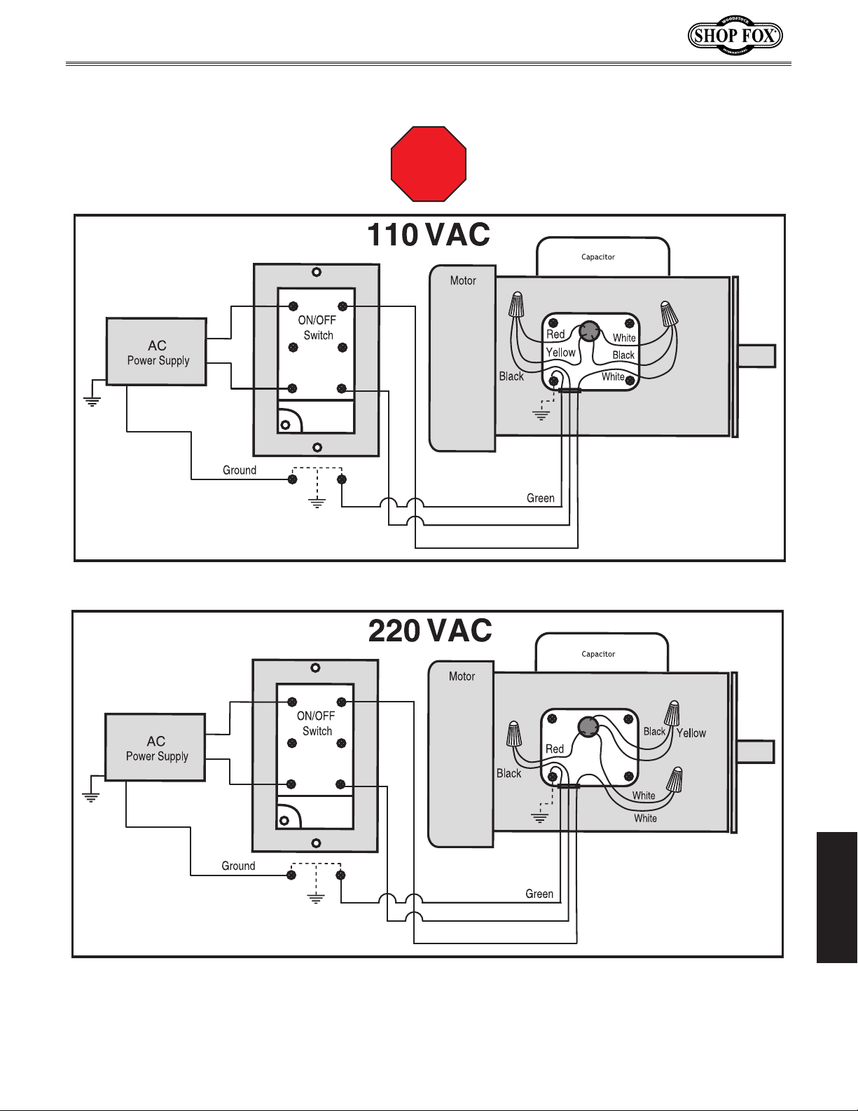
Model W1706 (Mfg. Since 3/13)
W1706 Wiring Diagram
Read
Page 50
STOP
Before
Wiring
-51-
SERVICE
Page 56

Troubleshooting
This section covers the most common problems and corrections with this type of
machine.
moving parts have come to a complete stop!
Motor will not start. 1. Low voltage.
Fuses or circuit breakers
trip open.
Motor overheats. 1. Motor overloaded.
Motor fails to develop full
power.
Motor stalls (resulting in
blown fuses or tripped
circuit).
Machine slows when
operating.
Blade does not run evenly
on wheels or runs off.
Blade slows when cutting;
machine makes a squealing
noise upon startup.
Ticking sound when
bandsaw is running.
Blade contacting table
insert.
SERVICE
Excessive vibration when
bandsaw is running.
WARNING! DO NOT make any adjustments until power is disconnected and
PROBLEM POSSIBLE CAUSE CORRECTIVE ACTION
1. Check power supply for proper voltage.
2. Open circuit in motor or loose
connections.
3. Faulty start capacitor.
1. Short circuit in line cord or plug.
2. Short circuit in motor or loose
connections.
3. Incorrect fuses or circuit breakers
in power supply.
2. Air circulation through the motor
restricted.
1. Power line overloaded with other
electrical devices.
2. Low power from the power source.
1. Short circuit in motor of loose
connections.
2. Low voltage.
3. Incorrect fuses or circuit breakers
in power line.
4. Motor overloaded.
1. Excessive feed rate.
2. Dull blade.
3. Incorrect blade for operation.
4. Binding the blade when cutting
curves.
5. Workpiece wet.
1. Tracking is not properly adjusted.
2. Wheels are not coplanar.
1. Belt loose.
2. Belt excessively worn.
1. Blade weld contacting guide bearings.
2. Motor fan or cover damaged.
3. Damaged blade; bent teeth.
1. Excessive side pressure on blade
when cutting.
2. Table not properly adjusted.
1. Machine sits on floor unevenly.
2. Wheels not coplanar.
3. Tires incorrectly installed.
4. Belt worn out.
5. Bent or damaged blade.
6. Wheel(s) out of balance.
2. Inspect all lead connections on motor and magnetic
switch for loose or open connections.
3. Replace start capacitor.
1. Inspect cord or plug for damaged insulation and
shorted wires and replace extension cord.
2. Inspect all connections on motor for loose or
shorted terminals or worn insulation.
3. Install correct fuses or circuit breakers.
1. Reduce load on motor.
2. Clean motor to provide normal air circulation.
1. Reduce load on power line.
2. Request a power check from the power company.
1. Inspect connections on motor for loose or shorted
terminals or worn insulation.
2. Correct the low voltage conditions.
3. Install correct fuses or circuit breaker.
4. Reduce load on motor.
1. Reduce feed rate.
2. Sharpen/replace blade.
3. Use correct blade for workpiece.
4. Make more relief cuts; use correct blade width for
operation.
5. If moisture content is higher than 20%, sticker and
allow to dry.
1. Properly adjust blade tracking (see Page 14).
2. Adjust wheel alignment (see Page 47).
1. Adjust belt tension (see Page 43).
2. Replace belt (see Page 44).
1. Use a stone to smooth blade weld.
2. Replace.
3. Replace blade.
1. Reduce side pressure on blade.
2. Properly align the table with the blade (see
Page 19).
1. Adjust rubber feet; shim if necessary.
2. Adjust wheel alignment (see Page 47).
3. Check/re-install/replace.
4. Replace belt (see Page 44).
5. Replace blade (see Page 39).
6 Replace wheel(s).
Model W1706 (Mfg. Since 3/13)
-52-
Page 57
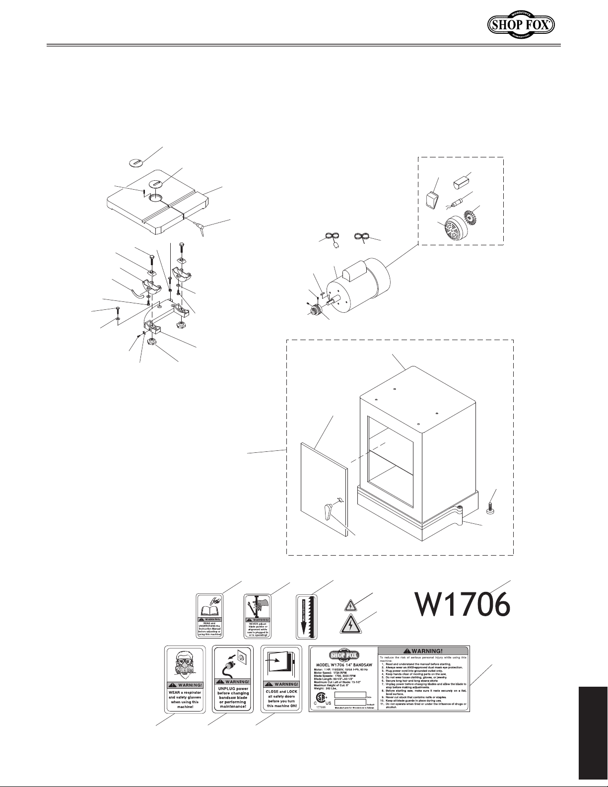
Model W1706 (Mfg. Since 3/13)
98-1
PARTS
Cabinet Stand
106
104
73
99
103
102
101
111
109
108
113
112
98
110
104-1
104
105
97
100
25V2
8
13
11V2
12
1-2
26V2
1-1
11V2-3
11V2-2
11V2-4
11V2-5
11V2-1
181
180
1
182
177
178
179
1-5
1-3
1-4
184
176
175
174V2
PARTS
-53-
Page 58
Model W1706 (Mfg. Since 3/13)
100 X1706100 TABLE LOCK PIN 184 X1706184 MODEL NUMBER LABEL
Cabinet Stand Parts List
REF PART # DESCRIPTION REF PART # DESCRIPTION
1 X1706001 CABINET STAND ASSEMBLY 101 X1706101 TRUNNION
1-1 X1706001-1 CABINET STAND 102 X1706102 TILT SCALE
1-2 X1706001-2 CABINET DOOR 103 X1706103 TRUNNION CLAMP SHOE
1-3 X1706001-3 BOTTOM BLACK STRIPE 104 X1706104 HEX BOLT 1/4-20 X 1/2
1-4 X1706001-4 HANDLE 104-1 X1706104-1 FLAT WASHER 1/4
1-5 X1706001-5 CABINET RUBBER FOOT 105 X1706105 TRUNNION BASE
8 X1706008 KEY 5 X 5 X 25 106 X1706106 HEX BOLT 5/16-18 X 1-1/4
11V2 X1706011V2 MOTOR 1HP 110V/220V 1PH V2.03.19 108 X1706108 POINTER
11V2-1 X1706011V2-1 MOTOR FAN V2.03.19 109 X1706109 PHLP HD SCR 10-24 X 1/4
11V2-2 X1706011V2-2 MOTOR FAN COVER V2.03.19 110 X1706110 TRUNNION LOCK KNOB 3/8-16
11V2-3 X1706011V2-3 MOTOR JUNCTION BOX V2.03.19 111 X1706111 HEX BOLT 3/8-16 X 2
11V2-4 X1706011V2-4 CAPACITOR COVER V2.03.19 112 X1706112 HEX BOLT 5/16-18 X 1-3/4
11V2-5 X1706011V2-5 S CAPACITOR 300M 125V V2.03.19 113 X1706113 HEX NUT 5/16-18
12 X1706012 MOTOR PULLEY 174V2 X1706174V2 MACHINE ID LABEL CSA V2.08.10
13 X1706013 SET SCREW 1/4-20 X 1/2 175 X1706175 ELECTRICITY LABEL LARGE
25V2 X1706025V2 POWER CORD 16G 3C 5-15 V2.08.10 176 X1706176 ELECTRICITY LABEL SMALL
26V2 X1706026V2 MOTOR CORD 16G 3C V2.08.10 177 X1706177 CLOSE DOOR WARNING LABEL
73 X1706073 LOCK WASHER 5/16 178 X1706178 BANDSAW ADJUST LABEL
97 X1706097 TABLE 179 X1706179 BLADE DIRECTION LABEL
98 X1706098 LARGE TABLE INSERT 180 X1706180 UNPLUG WARNING LABEL
98-1 X1706098-1 SMALL TABLE INSERT 181 X1706181 RESPIRATOR WARNING LABEL
99 X1706099 ROLL PIN 3 X 8 182 X1706182 READ MANUAL LABEL SMALL
Body Parts List
REF PART # DESCRIPTION REF PART # DESCRIPTION
2 X1760002 HEX BOLT 5/8-11 X 2-1/2 22 X1706022 WHEEL PULLEY
3 X1760003 FLAT WASHER 5/8 23 X1706023 PHLP HD SCR 10-24 X 5/8
4 X1706004 HEX NUT 5/8-11 24V2 X1706024V2 STRAIN RELIEF V2.08.10
5 X1706005 GUIDE PIN 6 X 5MM 28 X1706028 UPPER FRAME ARM
6 X1706006 LOWER WHEEL SHAFT 29 X1706029 KNOB BOLT 5/16-18 X 3/4
7 X1706007 BALL BEARING 6204-2RS 29-1 X1706029-1 KNOB BOLT 5/16-18 X 2
8 X1706008 KEY 5 X 5 X 25 30 X1706030 TENSION SPRING HOUSING
9 X1706009 FLAT WASHER 5/16 31 X1706031 WING NUT 5/16-18
10 X1706010 HEX BOLT 5/16-18 X 3/4 33 X1706033 TENSION BOLT 3/8-16 X 11-5/8
14V2 X1706014V2 PUSH BUTTON SWITCH V2.08.10 34 X1706034 PIVOT PIN
15 X1706015 TAP SCREW #10 X 3/4 35 X1706035 UPPER WHEEL SHAFT
16 X1706016 FLAT WASHER #10 35-1 X1706035-1 SHAFT BRACKET
17 X1706017 PHLP HD SCR 10-24 X 1/2 35-2 X1706035-2 ROLL PIN 4 X 30
19 X1706019 EXT TOOTH WASHER #10 38 X1706038 TENSION SPRING 3.8 X 76
20V2 X1706020V2 SWITCH BOX V2.08.10 39 X1706039 INDICATOR NUT 3/8 X 16
21 X1706021 SWITCH BRACKET 40 X1706040 UPPER WHEEL
PARTS
-54-
Page 59
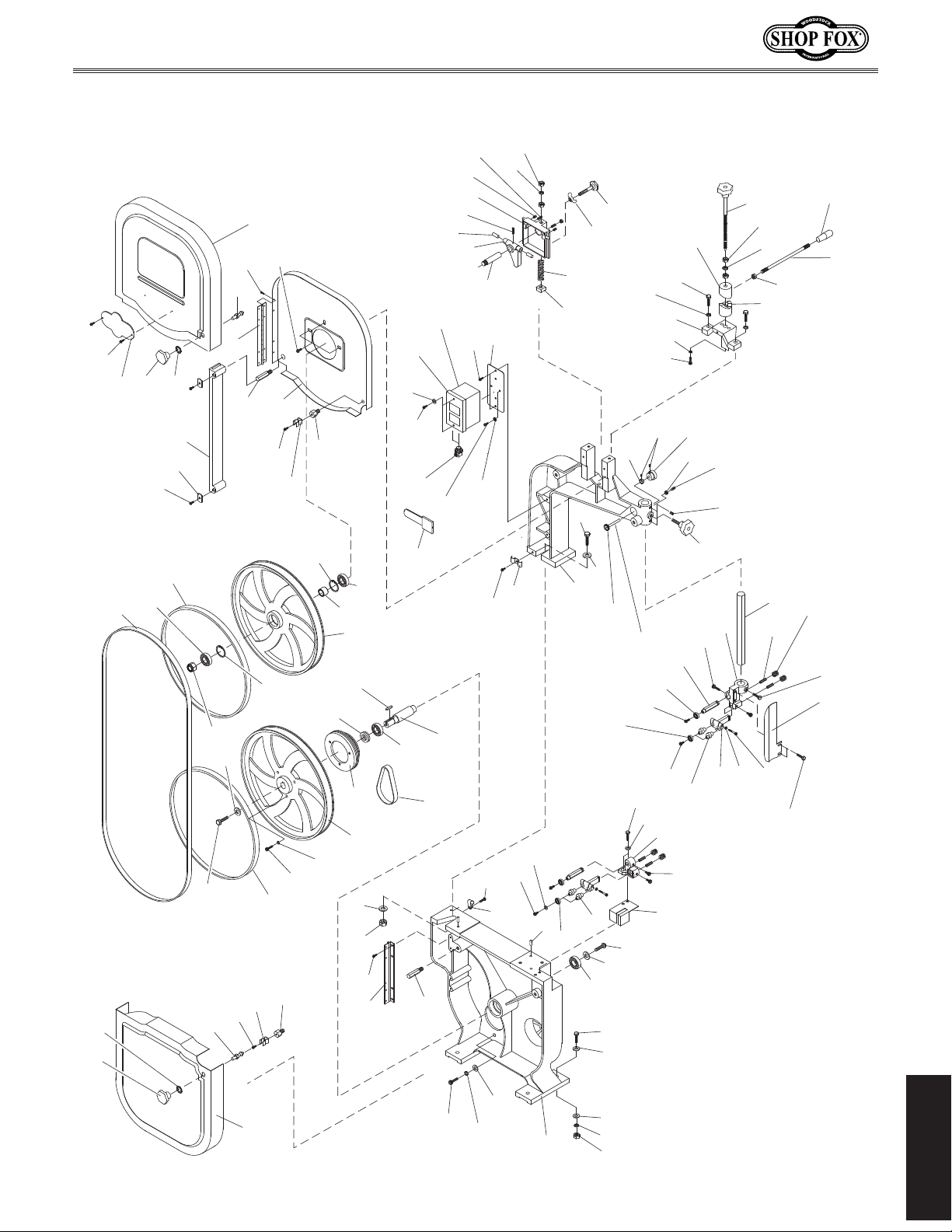
Model W1706 (Mfg. Since 3/13)
Body
151
50
49
150
60
49
44
67
41
50
66
65
47
51
42
46
63
55
51
58
64
59
56
55
43
62
61
41
57
56
154
57
43
45-1
167
173
40
8
22
45
3
4
70
44
69
14V2
16
15
24V2
186
7
35-2
34
35-1
20V2
23
6
68
64
155
168
30
17
19
35
76
125
141
21
124
131
75
96
127
5
39
128
38
2
28
118-1
129A
31
3
7
29-1
128
9
71
72
139
119
118
95
10
83
138
140
167
154
155
82
94
96
93
88
135
120
113
81
129A
80
29
80
170
79
89
162
85
33
131
141
135-1
121
86
84
134
133
131
122
123
90
92
48
115
116
-55-
117
185
72
73
74
PARTS
Page 60
Model W1706 (Mfg. Since 3/13)
Body Parts List
REF PART # DESCRIPTION REF PART # DESCRIPTION
41 X1706041 WHEEL TIRE 89 X1706089 GUIDE SHAFT BRACKET
42 X1706042 LOCK NUT 1/2-20 THIN 90 X1706090 GUIDE POST GUARD
43 X1706043 INT RETAINING RING 35MM 92 X1706092 PHLP HD SCR 10-24 X 3/8
44 X1706044 BALL BEARING 6202-2RS 93 X1706093 LOWER BLADE GUIDE CASTING
45 X1706045 LOWER WHEEL 94 X1706094 FLAT WASHER 1/4
45-1 X1706045-1 SHIM 19 X 29 X 1MM BRASS 95 X1706095 HEX BOLT 1/4-20 X 3/4
46 X1706046 LOWER WHEEL FLAT WASHER 5/16 96 X1706096 CAP SCREW 10-32 X 1/4
47 X1706047 HEX BOLT 5/16-18 X 3/4 LH 113 X1706113 HEX NUT 5/16-18
48 X1706048 LOWER WHEEL COVER 115 X1706115 HEX BOLT 5/16-18 X 1
49 X1706049 WHEEL COVER KNOB 5/16-18 116 X1706116 LOCK WASHER 5/16
50 X1706050 INT TOOTH WASHER 8MM 117 X1706117 FLAT WASHER 5/16
51 X1706051 STUD LATCH 118 X1706118 PINION SHAFT
55 X1706055 PHLP HD SCR 10-24 X 1/2 118-1 X1706118-1 PINION GEAR
56 X1706056 CATCH 119 X1706119 LOCK COLLAR
57 X1706057 LOCATING BOLT 3/8-16 X 1-3/32 120 X1706120 KNURLED KNOB 1/4-24
58 X1706058 TAP SCREW #8 X 3/8 121 X1706121 SET SCREW 5/16-24 X 1-3/4
59 X1706059 UPPER WHEEL COVER 122 X1706122 KNURLED KNOB 5/16-24
60 X1706060 SAW BLADE 6TPI X 93-1/2 X 3/8 123 X1706123 CAP SCREW 1/4-20 X 5/8
61 X1706061 UPPER WHEEL HOUSING 124 X1706124 CORD CLAMP 3/4"
62 X1706062 FLANGE SCREW 10-24 X 5/16 125 X1706125 PHLP HD SCR 10-24 X 1/2
63 X1706063 UPPER WHEEL COVER HINGE 127 X1706127 FLAT WASHER #10
64 X1706064 BLADE GUARD STUD 128 X1706128 BALL BEARING 608-2RS
65 X1706065 BLADE GUARD 129A X1706129A ECCENTRIC SHAFT 3/8" V2.09.04
66 X1706066 FLAT WASHER 28 X 16 X 2 131 X1706131 HEX NUT 3/8-16
67 X1706067 TAP SCREW #10 X 1/2 133 X1706133 QUICK RELEASE LEVER
68 X1706068 MULTI-GROOVE BELT 200J5 134 X1706134 LEVER KNOB
69 X1706069 LOWER WHEEL COVER HINGE 135 X1706135 UPPER CLUTCH
70 X1706070 PHLP HD SCR 10-24 X 3/8 135-1 X1706135-1 LOWER CLUTCH
71 X1706071 HEX BOLT 5/16-18 X 1-1/2 138 X1706138 HEX BOLT 5/16-18 X 1-1/4
72 X1706072 FLAT WASHER 5/16 139 X1706139 LOCK WASHER 5/16
73 X1706073 LOCK WASHER 5/16 140 X1706140 CLUTCH SUPPORT BRACKET
74 X1706074 HEX NUT 5/16-18 141 X1706141 LOCK WASHER 3/8
75 X1706075 DOUBLE CORD CLAMP 150 X1706150 SHOP FOX LOGO
76 X1706076 PHLP HD SCR 10-24 X 1/2 151 X1706151 TAP SCREW #4 X 3/8
79 X1706079 UPPER BLADE GUIDE CASTING 154 X1706154 CAP SCREW 1/4-20 X 1
80 X1706080 THUMBSCREW 1/4-20 X 1/4 155 X1706155 SET SCREW 1/4-20 X 5/16
81 X1706081 BEARING ARBOR 1/4-20 162 X1706162 BALL PLUNGER 1/4-20 X 1/2
82 X1706082 BALL BEARING 6000ZZ 167 X1706167 LOCK WASHER 1/4
83 X1706083 FLANGE SCREW 1/4-20 X 3/8 168 X1706168 SET SCREW 1/4-20 X 3/4
84 X1706084 GUIDE POST 170 X1706170 DOG POINT SET SCREW 1/4-20 X 1/2
85 X1706085 LOCK WASHER #10 173 X1706173 BUSHING
86 X1706086 CAP SCREW 10-24 x 1-1/4 185 X1706185 LOWER FRAME
88 X1706088 LOWER BLADE GUIDE BRACKET 186 X1706186 SWITCH PADLOCK
PARTS
-56-
Page 61
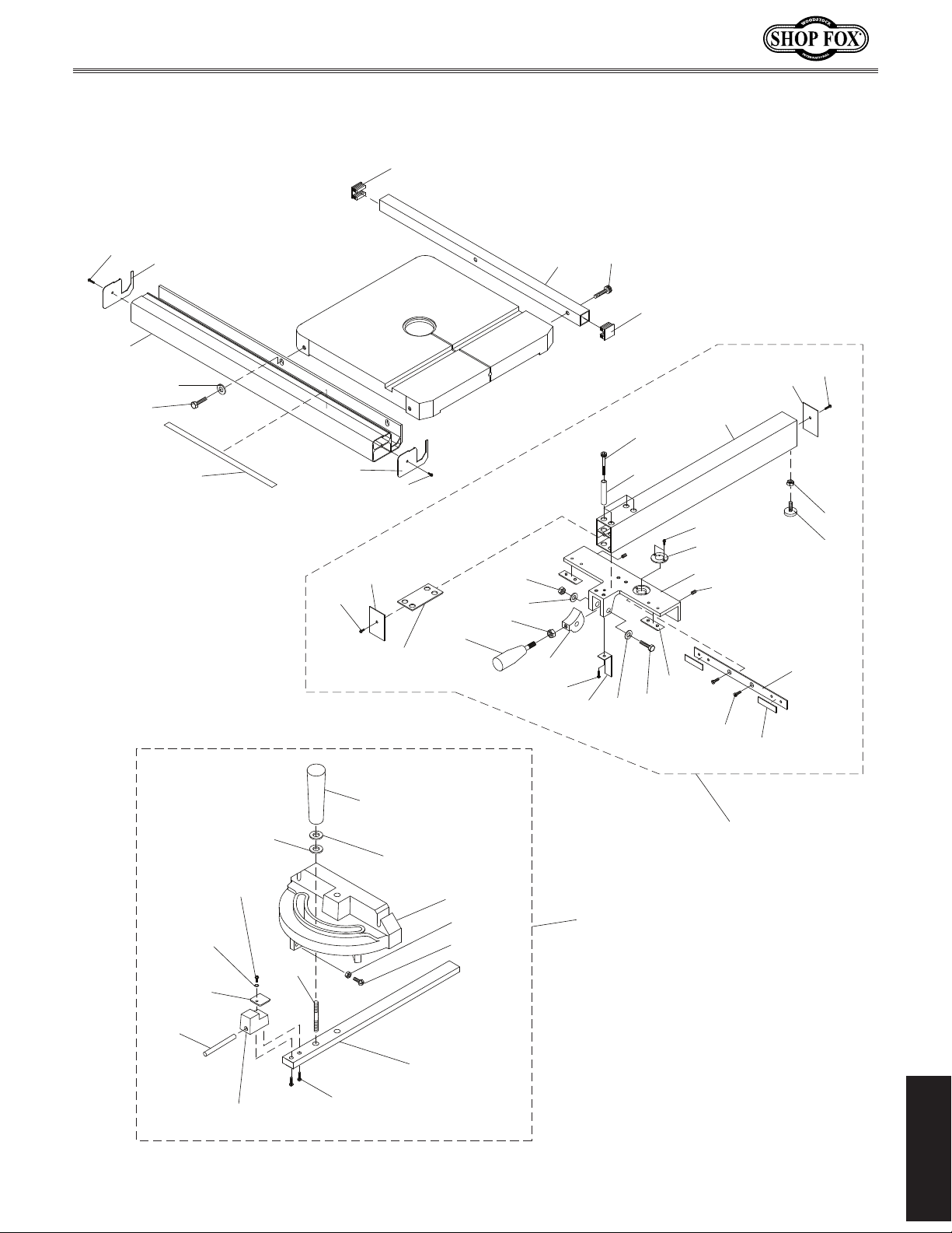
Model W1706 (Mfg. Since 3/13)
Fence & Miter Gauge
161
58
37
95
53
94
166
58
53
87
58
77-1
132
113
131
156
36
23
52
153
160
156
161
27
78
157
130
32
54
107
77
126
163
130
87
107-1
58
158
159
114-6
114-4
114-14
114-13
114-8
114-3
114-7
114-5
114-12
114-9
114-2
114-1
114-10
114-11
-57-
114
77-3
77-2 Fence Assembly
With Rails
PARTS
Page 62
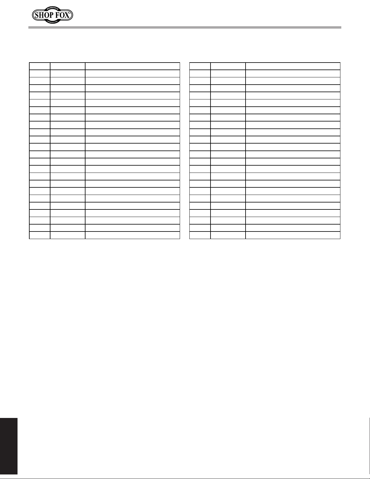
Model W1706 (Mfg. Since 3/13)
Fence & Miter Gauge Parts List
REF PART # DESCRIPTION REF PART # DESCRIPTION
23 X1706023 PHLP HD SCR 10-24 X 5/8 114-4 X1706114-4 STOP DOWEL
27 X1706027 CAP SCREW 1/4-20 X 2-1/2 114-5 X1706114-5 HANDLE 1/4-20
32 X1706032 PHLP HD SCR 8-32 X 1-1/4 114-6 X1706114-6 POINTER
36 X1706036 LOCK CAM 114-7 X1706114-7 STUD 1/4-20 X 1-1/8
37 X1706037 FRONT FENCE RAIL 114-8 X1706114-8 PLASTIC FLAT WASHER 1/4"
52 X1706052 REAR FENCE RAIL 114-9 X1706114-9 FLAT WASHER 1/4
53 X1706053 FRONT RAIL END CAP 114-10 X1706114-10 HEX NUT 10-24
54 X1706054 FENCE POINTER LENS 114-11 X1706114-11 PHLP HD SCR 10-24 X 3/4
58 X1706058 TAP SCREW #8 X 3/8 114-12 X1706114-12 PHLP HD SCR 10-24 X 1/4
77 X1706077 FENCE TUBE 114-13 X1706114-13 FLAT WASHER 5MM
77-1 X1706077-1 FENCE INSET PLATE 114-14 X1706114-14 PHLP HD SCR 10-24 X 1/4
77-2 X1706077-2 FENCE ASSEMBLY W/RAILS 126 X1706126 SET SCREW 5/16-18 X 3/8
77-3 X1706077-3 FENCE ASSEMBLY W/O RAILS 130 X1706130 BEARING PAD
78 X1706078 SLEEVE 131 X1706131 HEX NUT 3/8-16
87 X1706087 FENCE END CAP 132 X1706132 FENCE LOCK LEVER 5/16-18 X 5/8
94 X1706094 FLAT WASHER 1/4 153 X1706153 CAM WEAR PLATE
95 X1706095 HEX BOLT 1/4-20 X 3/4 156 X1706156 FLAT WASHER 3/8
107 X1706107 FENCE CARRIAGE 157 X1706157 HEX BOLT 3/8-16 X 2
107-1 X1706107-1 LOCKING PLATE 158 X1706158 HEX NUT M6-1
113 X1706113 HEX NUT 5/16-18 159 X1706159 RUB FOOT M6-1 X 15
114 X1706114 MITER GAUGE ASSEMBLY 160 X1706160 CAP SCREW 1/4-20 X 5/8
114-1 X1706114-1 MITER GAUGE BODY 161 X1706161 REAR RAIL END CAP
114-2 X1706114-2 MITER BAR 163 X1706163 FLAT HD SCR M6-1 X 6
114-3 X1706114-3 STOP BLOCK 166 X1706166 FENCE SCALE
PARTS
-58-
Page 63

Model W1706 (Mfg. Since 3/13)
Page 64

FOLD ALONG DOTTED LINE
FOLD ALONG DOTTED LINE
Place
Stamp
Here
Woodstock international inc.
p.o. box 2309
bellingham, Wa 98227-2309
TAPE ALONG EDGES--PLEASE DO NOT STAPLE
Page 65

WARRANTY
WARRANTY
Woodstock International, Inc. warrants all Shop Fox machinery to be free of defects from workmanship
and materials for a period of two years from the date of original purchase by the original owner. This
warranty does not apply to defects due directly or indirectly to misuse, abuse, negligence or accidents,
lack of maintenance, or reimbursement of third party expenses incurred.
Woodstock International, Inc. will repair, replace, or arrange for a dealer refund, at its expense and
option, the Shop Fox machine or machine part proven to be defective for its designed and intended
use, provided that the original owner returns the product prepaid to an authorized warranty or repair
facility as designated by our Bellingham, Washington office with proof of their purchase of the product
within two years, and provides Woodstock International, Inc. reasonable opportunity to verify the
alleged defect through inspection. If it is determined there is no defect, or that the defect resulted
from causes not within the scope of Woodstock International Inc.'s warranty, then the original owner
must bear the cost of storing and returning the product.
This is Woodstock International, Inc.’s sole written warranty and any and all warranties that may be
implied by law, including any merchantability or fitness, for any particular purpose, are hereby limited
to the duration of this written warranty. We do not warrant that Shop Fox machinery complies with
the provisions of any law, acts or electrical codes. We do not reimburse for third party repairs. In no
event shall Woodstock International, Inc.’s liability under this limited warranty exceed the purchase
price paid for the product, and any legal actions brought against Woodstock International, Inc. shall be
tried in the State of Washington, County of Whatcom. We shall in no event be liable for death, injuries
to persons or property or for incidental, contingent, special or consequential damages arising from the
use of our products.
Every effort has been made to ensure that all Shop Fox machinery meets high quality and durability
standards. We are commited to continuously improving the quality of our products, and reserve the
right to change specifications at any time.
Page 66

 Loading...