

Page 1

MODEL M1010
BENCHTOP
METAL BENDING SET
INSTRUCTION MANUAL
Phone: 1-360-734-3482 • On-Line Technical Support: tech-support@shopfox.biz
COPYRIGHT © OCTOBER, 2004 BY WOODSTOCK INTERNATIONAL, INC.
WARNI NG: NO PO RTION OF THI S MANUA L MAY B E REPRO DUCED IN ANY S HAPE OR F ORM WITHOU T
#6586 CR
THE WRI TTEN AP PROVAL OF WO ODSTO CK INTERNATIONA L, INC.
Print ed in Chi na
Page 2

Page 3

Contents
INTRODUCTION ..................................................................................................2
Woodstock Technical Support ............................................................................ 2
About Your New Benchtop Metal Bending Set ......................................................... 2
Specifications ............................................................................................... 2
Controls and Features ..................................................................................... 3
SAFETY ............................................................................................................4
Standard Safety Instructions ............................................................................. 4
Safety Steps for Benchtop Metal Bending Set ......................................................... 6
SET UP ............................................................................................................7
Inventory .................................................................................................... 7
Installation .................................................................................................. 7
OPERATIONS .....................................................................................................8
General ......................................................................................................8
Bend Tool .................................................................................................... 9
Twist Tool ..................................................................................................12
Scroll Tool ..................................................................................................13
MAINTENANCE ................................................................................................. 14
General .....................................................................................................14
Lubrication .................................................................................................14
PARTS ........................................................................................................... 15
Bend Tool ...................................................................................................15
Twist Tool .................................................................................................16
Scroll Tool ..................................................................................................17
Parts List ...................................................................................................18
WARRANTY ..................................................................................................... 20
SETUP MAINTENANCE PARTS WARRANTYOPERATIONSSAFETYINTRODUCTION
USE THE QUICK GUIDE PAGE LABELS TO SEARCH OUT INFORMATION FAST!
Page 4

M1010 Benchtop Metal Bending Set
INTRODUCTION
INTRODUCTION
Woodstock Technical Support
We stand behind our machines! In the event that a defect is found, parts are missing or questions arise
about your machine, please contact Woodstock International Technical Support at 1-360-734-3482 or
send e-mail to: tech-support@shopfox.biz. Our knowledgeable staff will help you troubleshoot prob-
lems, send out parts or arrange warranty returns.
If you need the latest edition of this manual, you can download it from http://www.shopfox.biz.
If you still have questions after reading the latest manual, or if you have comments please contact us at:
Woodstock International, Inc.
Attn: Technical Support Department
P.O. Box 2309
Bellingham, WA 98227
About Your New Benchtop Metal Bending Set
Your new SHOP FOX® Benchtop Metal Bending Set has been specially designed to provide many years of
trouble-free service. Close attention to detail, ruggedly built parts and a rigid quality control program
assure safe and reliable operation.
When mounted to a secure work bench, and with a complete set of jigs, your Benchtop Metal Bending
Set can make an incredible array of bent and twisted metal shapes with round, square, or rectangular
metal. These shaped metal pieces can be welded or fastened together to make ornate railings, supports, or framework for metal furnature.
Woodstock International, Inc. is committed to customer satisfaction in providing this manual. It is our
intent to make sure all the information necessary for safety, ease of assembly, practical use and durability of this product be included.
Specifications
Bend Tool for Mild Steel
Maximum Angle Range .................................................................. 60º to 90º
Maximum Round Stock Diameter .......................................................3/8" x 40"
Riveting Capacity ............................. (1/8" x 1-1/4"), (3/16" x 1-1/4"), (1/4" x 1-1/4")
Twist Tool for Mild Steel
Rectangular Metal Bar .........................................................1-1/4" x 1/4" x 40"
Square Metal Bar .........................................................................3/8" x 40"
Round Metal Bar ..........................................................................3/8" x 40"
Scroll Tool for Mild Steel
Rectangular Metal Bar ................................................................1-1/4" x 1/4"
Square Metal Bar ....................................................................... 3/8" x 3/8"
Round Metal Bar Diameter .....................................................................3/8"
Approximate Tool Weight .................................................................. 233 lbs.
-2-
Page 5
M1010 Benchtop Metal Bending Set
Controls and Features
This section summarizes the basic functions of each metal bending tool.
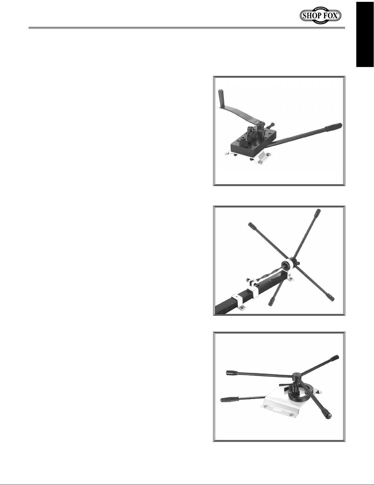
Bend Tool
Used to bend metal at precise angles ranging
from 0-60˚ and 0-90˚, depending on which side
of the bending block is used (see Figure 1).
Used to roll metal, make curves of various
degrees, diameters and shapes.
Used to clamp and rivet two pieces of metal
together.
INTRODUCTION
Twist Tool
Used to make decorative types of metal simply
by holding one end of the metal and turning, or
rotating the other end until the desired twist is
achieved (see Figure 2).
Scroll Tool
Used to make ornamental and useful type
scrolls. The scroll tool comes with two dies to
expand the capacity of the scroll effect (see
Figure 3).
Figure 1. Bend tool.
Figure 2. Twist tool.
-3-
Figure 3. Scroll tool.
Page 6

M1010 Benchtop Metal Bending Set
SAFETY
READ MANUAL BEFORE OPERATING TOOL.
FAILURE TO FOLLOW INSTRUCTIONS BELOW WILL
RESULT IN PERSONAL INJURY.
SAFETY
NOTICE
Indicates an imminently hazardous situation which, if not avoided, WILL
result in death or serious injury.
Indicates a potentially hazardous situation which, if not avoided, COULD
result in death or serious injury.
Indicates a potentially hazardous situation which, if not avoided, MAY
result in minor or moderate injury.
This symbol is used to alert the user to useful information about proper
operation of the equipment, and/or a situation that may cause damage
to the machinery.
Standard Safety Instructions
1. Thoroughly read the Instruction Manual before operating your tool. Learn the applications, limita-
tions and potential hazards of this tool. Keep the manual in a safe and convenient place for future
reference.
2. Keep work area clean and well lighted. Clutter and inadequate lighting invite potential hazards.
3. Wear eye protection at all times. Use safety glasses with side shields or safety goggles that meet
the appropriate standards of the American National Standards Institute (ANSI).
4. Ensure all levers, pins, pivots, dies, and mountings are securely in place and in working condition.
5. Keep work area clean, free of clutter, grease, etc.
6. Keep children and visitors away. Visitors must be kept at a safe distance while bending metal.
7. Childproof your workshop with padlocks, master switches or by removing starter keys.
8. Do not force tool. The tool will do a safer and better job at the rate for which it was designed.
9. Use correct tool. Do not force tool or attachment to do a job for which it was not designed.
10. Wear proper apparel. Do not wear loose clothing, neck ties, gloves, jewelry, and secure long hair
away from moving parts.
-4-
Page 7

M1010 Benchtop Metal Bending Set
11. Keep proper footing and balance at all times.
12. Perform tool maintenance and care. Follow lubrication and accessory attachment instructions in
the manual.
13. If at any time you are experiencing difficulties performing the intended operation, stop using the
tool! Then contact our technical support or ask a qualified expert how the operation should be performed.
14. Habits—good and bad—are hard to break. Develop good habits in your shop and safety will become
second-nature to you.
SAFETY
-5-
Page 8
M1010 Benchtop Metal Bending Set
Safety Steps for Benchtop Metal Bending Set
READ and understand this
entire instruction manual
before using these tools.
Serious personal injury may
occur if safety and oper-
SAFETY
1. FALLING HAZARD! Do not operate Benchtop Metal Bending Set unless it is bolted to a sturdy work-
bench.
2. UNCONTROLLED MOVEMENT HAZARD! Be aware that certain metals can snap or shear rather than
bend, causing a lever to unexpectedly move to a maximum distance causing injury. Always have a
stable footing and anticipate unexpected metal breakage.
3. OVERLOAD HAZARD! Never use a cheater pipe or crowbar to increase leverage, or you will break
the tool.
4. AMPUTATION HAZARD! Never position fingers in or near the mechanism or between dies when using
the tool.
ational information is not
understood and followed.
DO NOT risk your safety by
not reading!
USE this and other tools with caution and
respect. Always consider safety first, as it
applies to your individual working conditions.
No list of safety guidelines can be complete—
every shop environment is different. Failure
to follow guidelines could result in serious
personal injury, damage to equipment or
poor work results.
5. EYE HAZARD! Always wear safety glasses when using metal bending tools.
6. GENERAL SAFETY HAZARD! Do not modify any metal bending tool for a task other than what it is
designed for.
7. BREAKAGE HAZARD! Heat can weaken hardend metal. Never apply heat or weld on any metal while
it is installed in the tool, and never apply heat or weld on any metal bending tool, pivot pin, shaft,
lever or die.
8. LACK OF KNOWLEDGE HAZARD! If at any time you are experiencing difficulties performing the
intended operation, stop using the tool! Then contact our technical support or ask a qualified expert
how the operation should be performed.
-6-
Page 9

M1010 Benchtop Metal Bending Set
Inventory
SET UP
Refer to the list below and use Figure 4 to inventory
your package. If you notice the tool has been damaged
or is missing parts, contact your dealer or Woodstock
International Technical Support at 1-360-734-3482 or
send e-mail to: tech-support@shopfox.biz
A. Bending Tool Assembly ....................... 1
B. Twist Tool Assembly .......................... 1
C. Scroll Tool Assembly .......................... 1
D. Handle and Hardware Bag
—Twist Tool Handles .......................... 4
—Scroll Tool Handles .......................... 4
—Hex Wrenches 8mm, 10mm ................ 2
SUFFOCATION HAZARD!
Immediately discard all plastic bags
and packing materials to eliminate a
choking and suffocation hazard for
children and animals.
C
B
Figure 4. Inventory.
D
A
SETUP
Installation
To install the metal bending set, do these steps:
1. Thread the four handles into the twist tool hub as
shown in Figure 5.
2. Attach the hand lever to the bottom of the scroll tool
base as shown in Figure 6.
3. Before mounting the M1010 metal bending set to the
work surface, make sure the mounting surface is solid
enough to hold the tool and the work material.
4. Place each tool onto the work surface and make sure
adequate work room has been given on all sides as
shown in Figures 5, 6, and 7.
5. Using a pen or pencil, transfer the hole locations to
the mounting surface.
6. Drill and mount the tool to the work surface using 5⁄16"
bolts, washers, and nuts. Avoid using lag screws as
screws may pull out of the work surface.
Figure 5. Twist tool.
Figure 6. Scroll tool.
Figure 7. Bend tool.
-7-
Page 10

OPERATIONS
General
With the set of dies, your Benchtop Metal Bending Set
can make an incredible array of bent and twisted ornate
metal shapes. These round, square, or rectangular metal
shapes can then be welded or riveted together to make
ornate railings, supports, or framework for metal furniture. Figure 8 shows the basic bends listed below.
A Twisted Bar
B Large Roll
C Small Roll
D 45º Angle Bend
E 60º Angle Bend
F Scroll
Covered in this Operations section are the basic func-
SETUP
tions that you can do with each tool.
M1010 Benchtop Metal Bending Set
Always wear safety glasses when operating the Benchtop Metal Bending Set.
Failure to comply may result in serious
personal injury.
NOTICE
Bend Tool
Depending on which side of the bending block is
used, the bend tool can bend metal at precise angles
ranging from 0-60˚ and 0-90˚.
This tool can also roll metal, and make curves of
various degrees, diameters, and shapes.
There are two positions for the guide rollers. To
bend metal for smaller diameters and shapes, use
the inner set of holes. To bend larger diameters and
shapes, use the outer set of holes.
Riveting is another function that can be done to join
two pieces of metal together using rivets.
Twist tool
Use this tool to make decorative types of twisted
metal bars. Hold one end of the metal and turn the
levers at the other end until the desired twist is
achieved.
NEVER use a cheater pipe or a prybar
for additional leverage while bending
metal with these tools. If you ignore
this notice, you may break or bend
the tool and void your warranty.
A
C
B
F
E
Figure 8. Basic metal bends and twist.
D
F
C
B
Scroll tool
Use this tool to make ornamental and useful type
scrolls. The scroll tool comes with two dies to
expand the capacity of the scroll effect.
-8-
Page 11

M1010 Benchtop Metal Bending Set
Bend Tool
The bend tool produces many different sharp bends in
metal depending on the position of the bending block.
The roll feature can produce many different shapes and
sizes of arcs, or radii of metal.
Riveting is another function that this tool can perform.
Bending
Block
All three functions are covered in this procedure.
To bend metal to a particular angle, do these steps:
1. Select the appropriate bending block position.
Note: The bending block (Figure 9) has two main
positions. In one position the block can bend the
metal at a minimum angle of 60˚ (Figure 10), and
in the other position the block can bend metal at a
minimum angle of 90˚ (Figure 11).
2. Place the workpiece between the bending block and
the guide rollers (Figure 9).
3. With the desired angle of the bending block facing
the guide rollers, move the square handle until the
desired angle is reached. For more angle, move the
square handle farther and for less angle do not move
it as far.
4. Once the desired angle is reached, back off of the
bending block by moving the square handle the opposite direction. When there is enough clearance remove
the workpiece.
Figure 9. Bending block.
SETUP
Figure 10. Bending block positioned for a
60˚ bend.
Tip: Use the time-saving adjustment screw shown in
Figure 12. This screw is a stop or a reference point
that can be locked in place to ensure repeatability
of a bend.
5. After bending the workpiece to the desired angle,
turn the adjusting screw until it is tight against the
slide block, then tighten the lock nut.
-9-
Figure 11. Bending block positioned for a
90˚ bend.
Slide Block
Adjusting
Screw and
Nut
Figure 12
. Adjustment screw against the
slide block.
Page 12

To roll metal into a particular radii, do these steps:
1. With the hand lever, move the slide block so the bend
tool opens up and can accept the metal between the
feed roller and the guide rollers (Figure 13).
M1010 Benchtop Metal Bending Set
Note: If the adjustment screw is stopping the slide
block from moving, back off the adjustment screw
until the slide block opens all the way.
2. Select and move the guide rollers to the appropriate
set of holes.
• To bend metal for smaller radii, use the inner set
of holes (Figure 14).
• To bend metal for larger radii, use the outer
SETUP
set of holes (Figure 15).
3. Place the workpiece between the feed roller and the
guide rollers.
4. Using the hand lever, squeeze the workpiece between
the feed roller and the guide rollers.
5. Rotate the crank to start to form the workpiece. The
more you move the hand lever, the smaller the radius
will become.
Feed
Roller
Guide
Roller
Figure 13. Bend tool open and ready for
the workpiece.
6. Keep rotating the crank until the desired radius is
achieved.
Tip: Use the time-saving adjustment screw shown in
Figure 12. This screw is a stop or a reference point
that can be locked in place to ensure repeatability
of a bend.
To use the adjustment screw, do these steps:
1. When the desired radii is achieved, do not release
pressure on the hand lever until the adjustment screw
is snug against the slide block (Figure 12).
Figure 14. Guide rollers positioned in the
inner location for smaller radii.
Figure 15. Guide rollers positioned in the
outer location for larger radii.
-10-
Page 13

M1010 Benchtop Metal Bending Set
2. Tighten the adjustment nut until it is in contact with
the rear block (Figure 12).
3. Move the hand lever to take pressure off of the adjustment screw, back the adjustment screw out, allowing
the feed roller to move away from the guide rollers.
4. Insert another workpiece to be rolled.
Slide Block
5. Tighten the adjustment screw until the adjustment nut
contacts the back block to reference the workpiece.
To use the riveter, do these steps:
1. Mark the hole location.
2. Punch or drill the holes for the size rivet being used.
3. Move the hand lever to open the area between the
press rollers (Figure 17).
4. Place the two pieces of metal to be riveted together
(with the punched or drilled holes aligned) into the
space between the press rollers.
5. With the holes aligned, place the rivet in the hole and
center the rivet between the press rollers.
6. Move the square handle to squeeze the rivet between
the press rollers. The rivet must be squeezed to expand
enough to lock the two pieces of metal together.
Adjusting
Screw and
Nut
SETUP
Figure 16. Adjustment nut against the
back block.
Figure 17. Riveter open and ready for the
workpiece.
7. When the rivet is set, release the pressure on the
rivet, and spread the press rollers apart to remove the
riveted workpiece.
-11-
Page 14

Twist Tool
The twist tool allows you to produce twists or spirals in
metal by holding one end and twisting the other.
To twist a metal bar or rod, do these steps:
1. Insert the workpiece through the hub clamp until
the desired portion of the workpiece is shown, and
tighten the cap screws down on the hub clamp to hold
the workpiece (Figure 18).
2. Slide the fixed clamp bracket down the body of the
twist tool until it is in the proper location to clamp
the workpiece.
M1010 Benchtop Metal Bending Set
Hub Clamp
Workpiece
Fixed Clamp
3. Lock the workpiece down tightly with the cap screws
SETUP
located in the fixed clamp (Figure 18).
4. Retighten the cap screws in the hub clamp to ensure
that the workpiece is locked in place.
5. Using the handle bars, rotate the hub clamp until the
desired twist in the workpiece is acheived.
6. Loosen the cap screws on the hub clamp and the fixed
clamp to remove the workpiece.
Figure 18. Workpiece inserted through
the hub.
-12-
Page 15

M1010 Benchtop Metal Bending Set
Scroll Tool
The scroll tool is designed to wrap the workpiece around
the dies to make a spiral or a “scroll” shape.
To create a scroll shape, do these steps:
1. Choose the desired workpiece to scroll.
2. Slide the workpiece between the offset shaft and the
hub die assembly (Figure 19).
3. Rotate the hand lever to lock the workpiece (Figure
20).
4. Push the scroll tool handles clockwise to turn the hub
die assembly and start the scroll (Figure 20).
5. Use the hand lever to move the guide sleeve (Figure
19).
Note: You can manipulate the size of the scroll
while rotating the hub die assembly if so desired.
For larger scrolls, add the small and large dies in
this order as needed to reach the desired size scroll.
6. Once the workpiece has the desired look, loosen the
hand lever and remove the workpiece.
Guide
Sleeve
Figure 19. Workpiece placement for scroll
Scroll
Hand
Lever
Offset
Shaft
the scroll operation.
Die Assemb
Hub
ly
Scroll
Tool
Handle
SETUP
-13-
Figure 20. A finished scroll wrapped
around the dies.
Page 16

M1010 Benchtop Metal Bending Set
MAINTENANCE
LubricationGeneral
Regular periodic maintenance on your SHOP
®
FOX
performance. Make a habit of inspecting your
metal bending tools before you use them.
Check for the following conditions and repair
or replace when necessary:
• Loose mounting bolts.
• Worn or cracked pins, levers, handles, and
• Any other condition that could hamper the
Model M1010 will ensure its optimum
fasteners.
safe operation of this machine.
Periodically put a drop of light machine oil at
all pivot points to ensure unbinding operation.
Flat metal surfaces can be kept rust-free with
regular applications of a product like SLIPIT®.
For long term storage you may want to consider
a product like Boeshield T-9™.
MAINTENANCE
-14-
Page 17

M1010 Benchtop Metal Bending Set
PARTS
Bend Tool
-15-
PARTS
Page 18

Twist Tool
M1010 Benchtop Metal Bending Set
PARTS
-16-
Page 19

M1010 Benchtop Metal Bending Set
Scroll Tool
-17-
PARTS
Page 20

Parts List
M1010 Benchtop Metal Bending Set
REF PART # DESCRIPTION
1 XM1010001 REAR BLOCK
2 XM1010002 LEFT BLOCK
3 XM1010003 GUIDE ROLLER
4 XM1010004 FEED ROLLER
5 XM1010005 BENDING BLOCK
6 XM1010006 HAND LEVER
7 XM1010007 SPECIAL BOLT M15 X 50
8 XPSB77M CAP SCREW M12-1.75 X 30
9 XM1010009 SPECIAL BOLT M15 X 35
10 XPSB59M CAP SCREW M10-1.5 X 40
11 XM1010011 PRESS WHEEL
12 XPSB88M CAP SCREW M10-1.5 X 25
13 XM1010013 FRONT BLOCK
14 XM1010014 SLIDE BLOCK
15 XM1010015 MOUNTING BRACKET
16 XM1010016 CRANK HANDLE
17 XPW03M FLAT WASHER 6MM
18 XPS37M PHLP HD SCREW M6-1 X 6
19 XPSB100M CAP SCREW M8-1.25 X 15
20 XPSB14M CAP SCREW M8-1.25 X 20
21 XPLW04M LOCK WASHER 8MM
22 XPSB84M CAP SCREW M10-1.5 X 35
23 XPSB59M CAP SCREW M10-1.5 X 40
24 XPW04M FLAT WASHER 10MM
25 XM1010025 HANDLE
26 XM1010026 BUSHING
27 XM1010027 HANDLE GRIP
28 XM1010028 BASE
29 XM1010029 ADJUSTMENT SCREW
30 XM1010030 RIGHT BLOCK
31 XPN02M HEX NUT M10-1.5
101 XPSB36M CAP SCREW M12-1.75 X 25
102 XM1010102 CLAMP BRACKET
103 XPSB92M CAP SCREW M12-1.75 X 40
104 XPS30M PHLP HD SCR M8-1.25 X 15
105 XM1010105 HUB
106 XPN01M HEX NUT M6-1
107 XPAW08M HEX WRENCH 8MM
108 XPAW10M HEX WRENCH 10MM
REF PART # DESCRIPTION
109 XPSS01M SET SCREW M6-1 X 10
110 XPN03M HEX NUT M8-1.25
111 XM1010111 HANDLE GRIP
112 XM1010112 HANDLE BAR
113 XM1010113 MOUNTING BRACKET
114 XPSB92M CAP SCREW M12-1.75 X 40
115 XM1010115 SET COLLAR
116 XM1010116 BODY
117 XPSB36M CAP SCREW M12-1.75 X 25
118 XPS14M PHLP HD SCR M6-1 X 12
119 XM1010119 MOUNTING BRACKET
201 XM1010201 SPACER (SMALL)
202 XM1010202 SPACER (LARGE)
203 XM1010203 GUIDE SLEEVE
204 XM1010204 GUIDE PLATE
205 XPS14M PHLP HD SCR M6-1 X 12
206 XM1010206 HOOK
207 XM1010207 HANDLE BAR
208 XM1010208 SPRING
209 XPS26M PHLP HD SCR M6-1 X 20
210 XM1010210 SQUARE HANDLE GRIP
211 XPN01M HEX NUT M6-1
212 XM1010212 SET COLLAR
213 XPSS03M SET SCREW M6-1 X 8
214 XM1010214 SPRING GUIDE BOLT
215 XM1010215 MOUNTING BRACKET
216 XPN09M HEX NUT M12-1.75
217 XM1010217 ARBOR
218 XM1010218 SMALL DIE
219 XM1010219 HUB DIE ASSEMBLY
220 XM1010220 OFFSET SHAFT (LONG)
221 XM1010221 OFFSET SHAFT (SHORT)
222 XM1010222 GRIP
223 XM1010223 HANDLE BAR
224 XM1010224 CLAMP HANDLE
225 XM1010225 DIE PIN
226 XM1010226 LARGE DIE
227 XM1010227 SPECIAL BOLT M15 X 45
PARTS
-18-
Page 21

M1010 Benchtop Metal Bending Set
Notes
-19-
Page 22

M1010 Benchtop Metal Bending Set
WARRANTY
Woodstock International, Inc. warrants all SHOP FOX® machinery to be free of defects from workmanship and materials for a period of 2 years from the date of original purchase by the original owner.
This warranty does not apply to defects due directly or indirectly to misuse, abuse, negligence or
accidents, lack of maintenance, or to repairs or alterations made or specifically authorized by anyone
other than Woodstock International, Inc.
Woodstock International, Inc. will repair or replace, at its expense and at its option, the SHOP FOX®
machine or machine part which in normal use has proven to be defective, provided that the original
owner returns the product prepaid to the SHOP FOX® factory service center or authorized repair
facility designated by our Bellingham, WA office, with proof of their purchase of the product within 2
years, and provides Woodstock International, Inc. reasonable opportunity to verify the alleged defect
through inspection. If it is determined there is no defect, or that the defect resulted from causes not
within the scope of Woodstock International Inc.'s warranty, then the original owner must bear the
cost of storing and returning the product.
This is Woodstock International, Inc.'s sole written warranty and any and all warranties that may be
implied by law, including any merchantability or fitness, for any particular purpose, are hereby limited
to the duration of this written warranty. We do not warrant that SHOP FOX® machinery complies
with the provisions of any law or acts. In no event shall Woodstock International, Inc.'s liability under
this warranty exceed the purchase price paid for the product, and any legal actions brought against
Woodstock International, Inc. Shall be tried in the State of Washington, County of Whatcom. We shall
in no event be liable for death, injuries to persons or property or for incidental, contingent, special or
consequential damages arising from the use of our products.
Every effort has been made to ensure that all SHOP FOX® machinery meets high quality and durability standards. We reserve the right to change specifications at any time because of our commitment to
continuously improve the quality of our products.
WARRANRTY
-20-
Page 23

WARRANTY REGISTRATION
Name___________________________________________________________________________________________
Street___________________________________________________________________________________________
City _______________________________________________________________State________Zip______________
Phone Number_______________________E-Mail_______________________FAX_________ ____________________
MODEL # SERIAL # DEALER NAME PURCHASE DATE / /
The following information is given on a voluntary basis and is strictly confidential.
1. How did you first learn about us?
9. What stationary woodworking tools do you own? Check all that apply.
___Advertisement ___Friend
___Mail order Catalog ___Local Store
___World Wide Web Site
___Other__________________________________________________
2. Which of the following magazines do you subscribe to.
___Cabinetmaker ___WOOD
___Family Handyman ___Wooden Boat
___Fine Homebuilding ___Woodshop News
___Woodsmith ___Today’s Homeowner
___Home Handyman ___Woodwork
___Journal of Light Construction ___Woodworker
___Old House Journal ___Woodworker’s Journal
___Popular Mechanics ___Workbench
___Popular Science ___American How-To
___Popular Woodworking
___Other__________________________________________________
3. Which of the following woodworking/remodeling shows do you watch?
___Backyard America ___The New Yankee Workshop
___Home Time ___This Old House
CUT ALONG DOTTED LINE
___The American Woodworker ___Woodwright’s Shop
___Other__________________________________________________
4. What is your annual household income?
___$20,000-$29,999 ___$60,000-$69,999
___$30,000-$39,999 ___$70,000-$79,999
___$40,000-$49,999 ___$80,000-$89,999
___$50,000-$59,999 ___$90,000 +
5. What is your age group?
___Air Compressor ___Panel Saw
___Band Saw ___Planer
___Drill Press ___Power Feeder
___Drum Sander ___Radial Arm Saw
___Dust Collector ___Shaper
___Horizontal Boring Machine ___Spindle Sander
___Jointer ___Table Saw
___Lathe ___Vacuum Veneer Press
___Mortiser ___Wide Belt Sander
___Other__________________________________________________
10. Which benchtop tools do you own? Check all that apply.
___1" x 42" Belt Sander ___6" - 8" Grinder
___5" - 8" Drill Press ___Mini Lathe
___8" Table Saw ___10" - 12" Thickness Planer
___Benchtop Metal Bending Set ___Scroll Saw
___Disc/Belt Sander ___Spindle/Belt Sander
___Mini Jointer
___Other__________________________________________________
11. Which portable/hand held power tools do you own? Check all that
apply.
___Belt Sander ___Orbital Sander
___Biscuit Joiner ___Palm Sander
___Circular Saw ___Portable Planer
___Detail Sander ___Saber Saw
___Drill/Driver ___Reciprocating Saw
___Miter Saw ___Router
___Other__________________________________________________
12. What machines/supplies would you like to see?
__________________________________________________________
__________________________________________________________
__________________________________________________________
__________________________________________________________
___20-29 ___50-59
___30-39 ___60-69
___40-49 ___70 +
6. How long have you been a woodworker?
___0 - 2 Years ___8 - 20 Years
___2 - 8 Years ___20+ Years
7. How would you rank your woodworking skills?
___Simple ___Advanced
___Intermediate ___Master Craftsman
8. How many SHOP FOX® machines do you own? ___________________
13. What new accessories would you like Woodstock International to carry?
__________________________________________________________
__________________________________________________________
14. Do you think your purchase represents good value?
___Yes ___No
15. Would you recommend SHOP FOX® products to a friend?
___Yes ___No
16. Comments:________________________________________________
__________________________________________________________
__________________________________________________________
__________________________________________________________
__________________________________________________________
Page 24

FOLD ALONG DOTTED LINE
FOLD ALONG DOTTED LINE
Place
Stamp
Here
WOODSTOCK INTERNATIONAL INC.
P.O. BOX 2309
BELLINGHAM, WA 98227-2309
TAPE ALONG EDGES--PLEASE DO NOT STAPLE
 Loading...