

Page 1
Model D4666
HEAVY-DUTY MOBILE BASE
Instruction Sheet
Phone #: (360) 734-3482 • Online Tech Support: [email protected] • Web: www.shopfox.biz
Introduction
Your new Model D4666 Heavy-Duty Mobile Base is
designed to give you a stable and mobile platform upon
which to mount machinery and equipment.
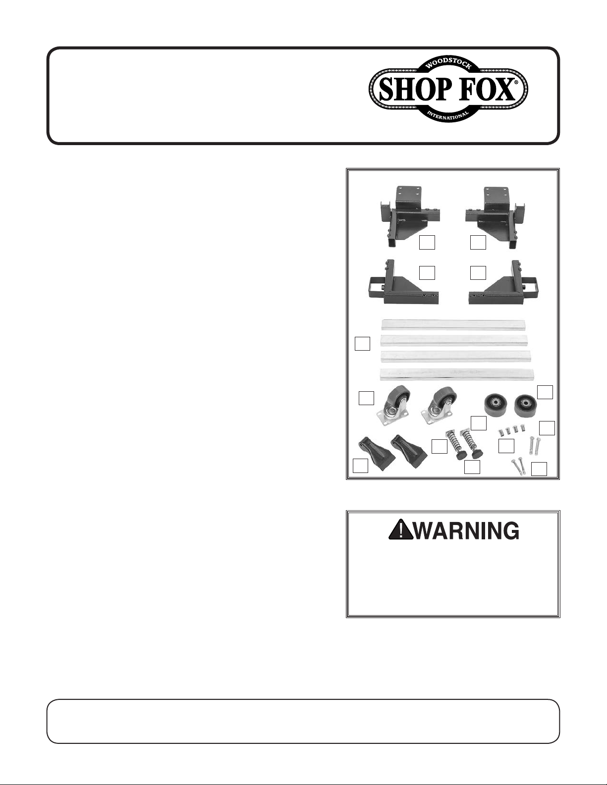
Inventory (Figure 1)
A. Right Front Corner Bracket ..............................1
B. Left Front Corner Bracket................................1
C. Right Rear Corner Bracket ...............................1
D. Left Rear Corner Bracket .................................1
E. 21" Side Rails ...............................................4
F. 3" Swivel Casters ..........................................2
G. 3" Wheels ...................................................2
H. Foot Pedals .................................................4
I. Foot Pedal Springs .........................................2
J. Foot Pedal Plungers .......................................2
K. Adjustable Rubber Feet ..................................2
L. Bearing Sleeves ............................................4
M. Shoulder Bolts M10-1.5 x 55 (Casters) .................2
N. Shoulder Bolts M8-1.25 x 52 (Pedals) ..................2
O. Hardware (Not Shown)
—Hex Bolts M8-1.25 x 16 (Brackets) .................. 24
—Hex Nuts M10-1.5 (Rubber Feet) ......................2
—Lock Nuts M8-1.25 (Caster/Pedal) .................. 10
—Lock Nuts M10-1.5 (Casters) ...........................2
A
C
E
F
I
H
Figure 1. Model D4666.
B
D
J
L
K
G
M
N
Specifications
• Minimum Inside Dimensions .................... 19" x 21"
• Maximum Inside Dimensions ............. 29
• Maximum Weight Capacity ...................... 1200 lbs
1
⁄2" x 291⁄2"
Items Needed for Assembly
• Open-End Wrench or Socket 13mm .....................1
• Open-End Wrench or Socket 14mm .....................1
• Open-End Wrench or Socket 17mm .....................1
• Measuring Tape.............................................1
COPYRIGHT © APRIL, 2017 BY WOODSTOCK INTERNATIONAL, INC. REVISED NOVEMBER, 2017 (HE)
WARNING: NO PORTION OF THIS MANUAL MAY BE REPRODUCED IN ANY SHAPE OR FORM WITHOUT
THE WRITTEN APPROVAL OF WOODSTOCK INTERNATIONAL, INC.
Operating machinery on an unsecured
mobile base may allow the machine
to shift unexpectedly, which could
result in accidental contact with the
cutting device or other moving parts.
Printed in China#18887JH
Page 2
D4666 Heavy-Duty Mobile Base
Straining or crushing
improperly lifting the
parts. To reduce this
Preparation for Assembly
There is more than one way to assemble the mobile base.
Each method has advantages and disadvantages, depending on the size and weight of the machine that you plan
to put on the mobile base. The purpose of this section is
to help you decide which method will work best for your
situation.
If the machine can be lifted, the easiest method is to
assemble the mobile base according to the dimensions of
your machine, and then lift and place the machine on the
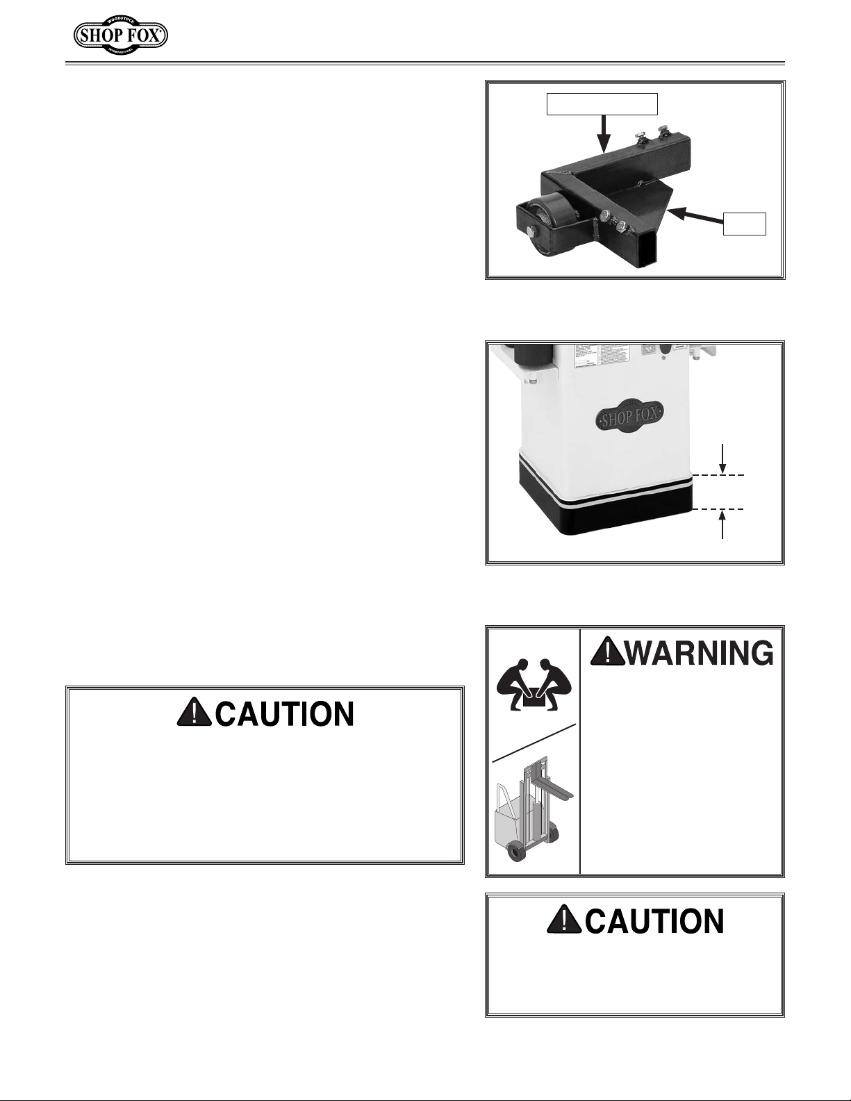
corner bracket plates of the mobile base (see Figure 2).
Proceed to Assembling Base & Mounting Machine on
Page 3 if your machine fits this situation.
If the machine is top heavy or has a narrow base (such as
a drill press), there is an increased risk of tipping when
moving it around on a mobile base. To reduce the risk, a
mounting base plate should be used between the mobile
base and machine. Proceed to Making a Base Plate on
Page 8 if your machine fits this situation.
If the machine is too heavy to lift into position on the
mobile base, then the base can be built around the
machine. Proceed to Assembling Base Around Machine
on Page 5 for instructions on how to build the base
around the machine.
Note: Anything extending or opening outward with a 3"
high band around the base of the machine (see Figure 3)
may interfere with the installation of the machine on the
base, so be sure to account for that prior to assembly.
Corner Bracket
Plate
Figure 2. One of four corner brackets the
machine will sit on.
3"
Figure 3. Example of 3" high band on
machine base.
Before moving machine and mobile base, check to
make sure pathway is clear of any hoses, wires, tools
or shop debris. An abrupt impact with an object
along path of travel can lock a wheel and cause
machine to fall over, resulting in serious personal
injury. Disconnect machine from power supply or
dust collection before moving.
-2-
HEAVY LIFT!
injury may occur from
machine or some of its
risk, get help from other
people and use a forklift
(or other lifting equipment) rated for weight of
machine.
To avoid serious personal injury, keep
hands and fingers clear of machine
base and mobile base pinch points
when placing machine.
Page 3
D4666 Heavy-Duty Mobile Base
Assembling Base & Mounting Machine
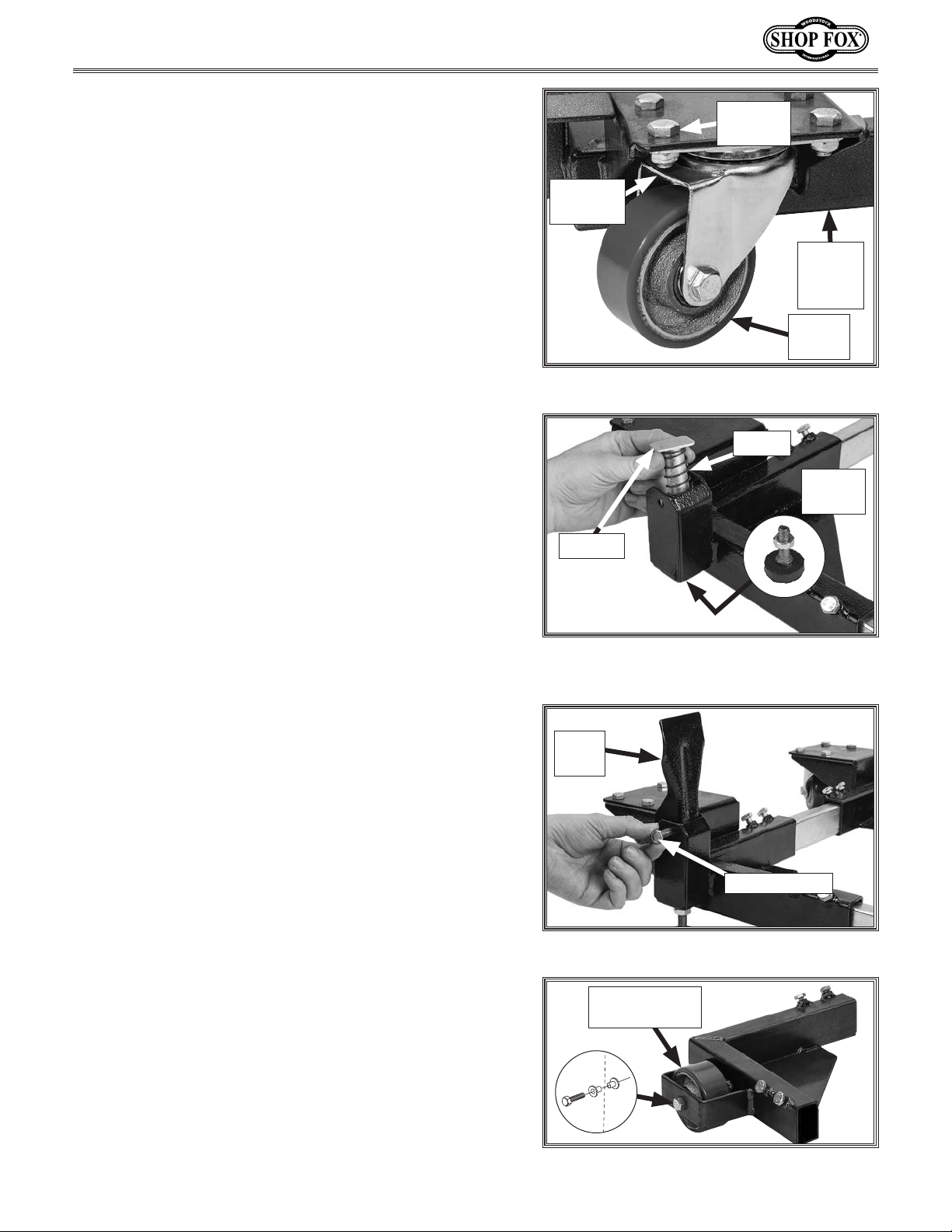
1. Attach swivel casters to both front corner using (4)
M8-1.25 x 16 hex bolts and (4) M8-1.25 lock nuts
(see Figure 4).
2. Install a foot pedal plunger and spring into each of
the front corner brackets (see Figure 5), and attach
a rubber foot (with M10-1.5 hex nut) to the bottom
of each foot pedal plunger.
Hex Bolt
(1 of 4)
Lock Nut
(1 of 4)
Front
Corner
Bracket
Swivel
Caster
Figure 4. Swivel caster attached.
Spring
Rubber
Foot
Plunger
3. Attach each foot pedal to front corner bracket using
(1) M8-1.25 x 52 shoulder bolt and (1) M8-1.25 lock
nut (see Figure 6).
4. Install each fixed caster wheels to rear corner brackets using (1) M10-1.5 x 55 shoulder bolt and bearing
sleeves (see Figure 7).
Figure 5. Installing foot pedal plunger and
spring.
Foot
Pedal
Shoulder Bolt
Figure 6. Attaching foot pedal.
Fixed Caster
Wheel
-3-
Figure 7. Fixed wheel attached.
Page 4
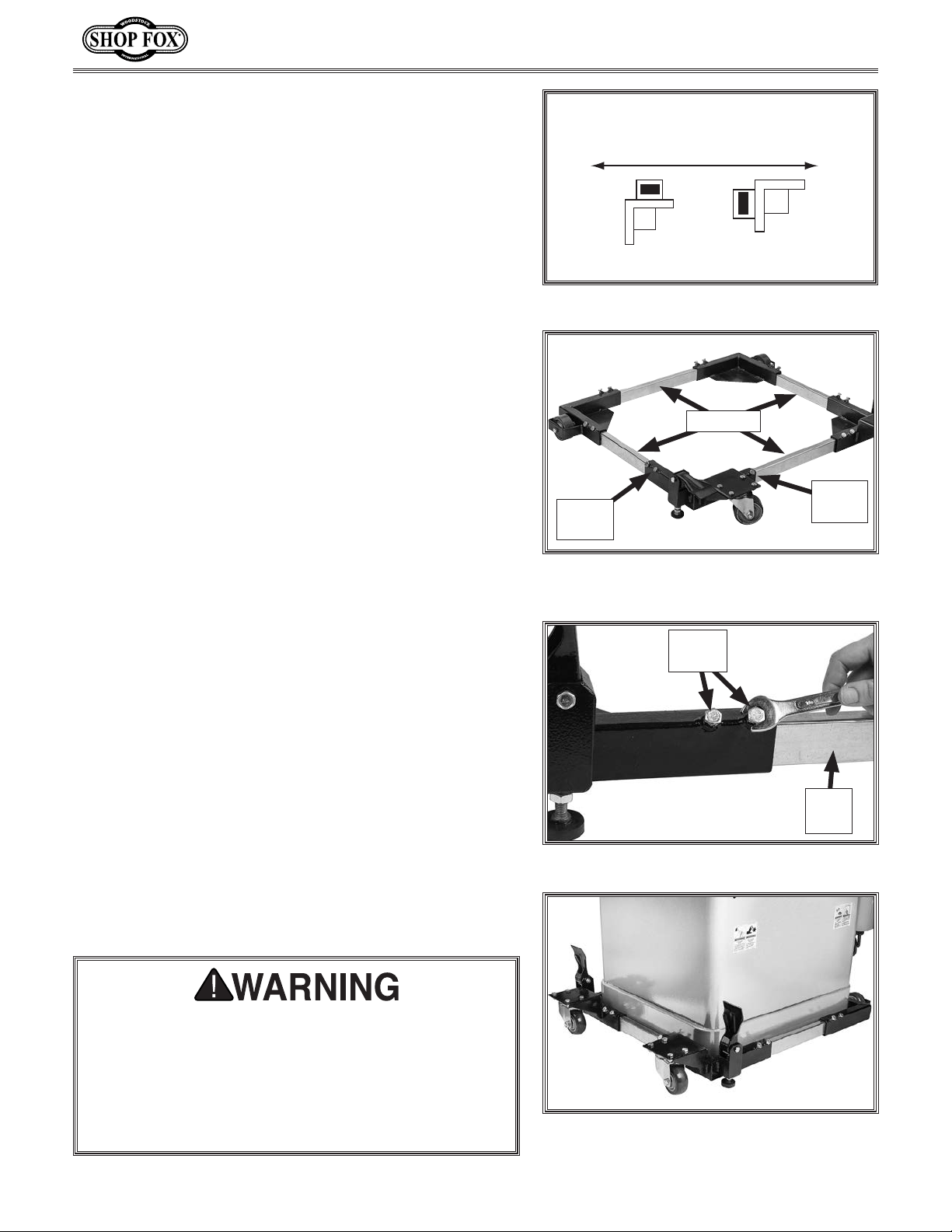
5. Orient fixed casters in same direction that machine
will typically be moved (see Figure 8). Mounting
fixed casters in wrong direction may make it difficult
to move mobile base around in small spaces.
6. Measure your machine base.
7. Slide each side rail into a corner bracket. Adjust
each side rail until mobile base inside measurement
(see Figure 9) matches base measurement of your
machine.
D4666 Heavy-Duty Mobile Base
(TOP VIEW OF CASTER)
Typical Direction of Movement
CORRECT INCORRECT
Figure 8. Fixed caster orientation.
Measure
8. Secure each side of side rails to corner brackets
using (2) M8-1.25 x 16 hex bolts in corner
brackets (see Figure 10).
1
Tip: Providing an extra
⁄4" of space around the base
measurement allows for easier machine fit during
assembly.
9. With the help of an assistant, or proper lifting equipment, lift and position machine inside mobile base
(see Figure 11).
10. Check to make sure the machine is properly seated
on the pads and that there is no sign of stress or
deflection in the mobile base.
— If there is any deflection, immediately remove the
machine from the base and check that all fasteners have been tightened and the base is properly
assembled. If this does not solve the problem,
double check the weight specification of the
machine and make certain it does not exceed the
load limit listed in Specifications on Page 1.
Insert
Hex
Rail
Bolts
Figure 9. Measuring inside width of mobile
base.
Hex
Bolts
Side
Rail
Figure 10. Securing rail to corner bracket.
Each side rail-to-bracket connection must use both
hex bolts, making a total of four bolts at each corner.
DO NOT load machine onto base until all bolts have
been installed and tightened. Loading a machine
onto base before completing assembly can result in
machine falling or tipping over, resulting in serious
personal injury.
-4-
Figure 11. Example of machine placed
inside mobile base.
Page 5
D4666 Heavy-Duty Mobile Base
Assembling Base Around Machine
The D4666 Mobile Base can assembled around oddly
shaped or heavy machinery. Always have an assistant
stabilize machine during mobile base assembly.
Items Needed Qty
Additional Person ...............................................1
Open-End Wrench 13mm.......................................1
Socket Wrench 13mm ..........................................1
12" 4x4 Block ....................................................1
12" 2x4 Block ....................................................1
To assemble base around machine, do these steps:
Spring
Rubber
Foot
Plunger
Figure 12. Installing foot lever assembly.
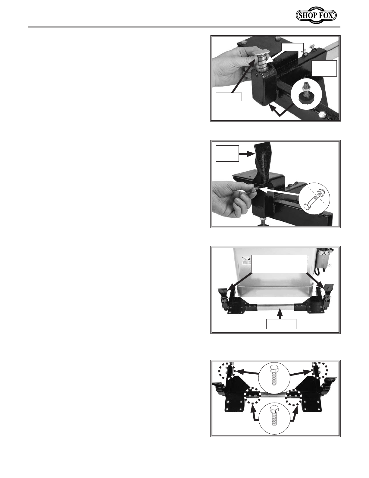
1. Install a foot pedal plunger and spring into each
of the front corner brackets (see Figure 12), and
attach a rubber foot (with M10-1.5 hex nut) to bottom of foot lever plunger.
2. Attach each foot pedal to front corner bracket using
(1) M8-1.25 x 52 shoulder bolt and (1) M8-1.25 lock
nut (see Figure 13).
3. Insert one side rail into the two front brackets, as
shown in Figure 14, then slide the bracket assembly
against the side of machine that will typically be
pushed against when moving the machine.
Foot
Lever
Figure 13. Attaching foot pedal.
Corner Brackets
with Rubber Feet
Side Rail
4. Secure each side rail to corner brackets with (4)
M8-1.25 x 16 hex bolts, as shown in Figure 15.
5. Slide other side rails into corner brackets from Step
4. Secure rails to corner brackets with (4) M8-1.25 x
16 hex bolts, as shown in Figure 15.
-5-
Figure 14. Rail inserted between corner
brackets with rubber feet.
x 4
x 4
Figure 15. Rails fastened to brackets
(machine removed for clarity).
Page 6
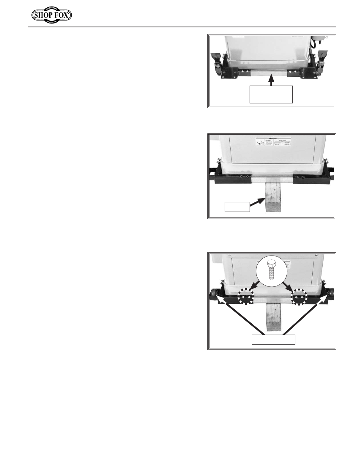
6. While an assistant lifts one side of the machine,
slide rail-bracket assembly from Step 5 under
machine, as shown in Figure 16.
Note: It may be necessary to re-adjust position of
rails once machine is actually on base assembly.
D4666 Heavy-Duty Mobile Base
Side rails may be cut down to accommodate
machines with smaller footprints. However, reducing length of mobile base decreases stability and
increases likelihood of tipping tall or top-heavy
machines. Base plates should be constructed for tall
or top-heavy machines (see Page 8).
7. With the help of an assistant, lift rear side of
machine, then place a 4x4 block under machine
(see Figure 17).
8. Slide each of the corner brackets onto remaining side rail, and slide assembly into rail-bracket
assembly from Step 6. Adjust fit until rail-bracket assembly rests against machine body (see
Figure 17).
9. Secure rail to corner brackets using (4) M8-1.25 x 16
hex bolts, as shown in Figure 18.
Rail-Bracket
Assembly
Figure 16. Rail-bracket assembly placed
under front of machine.
12" 4x4
Figure 17. Remaining brackets and rail
placed around back of machine, which is
raised up with a wood block
10. With machine still propped on 4x4 block, install both
fixed wheels using (2) M10-1.5 x 55 shoulder bolts
(see Figure 18).
11. With the help of an assistant, shift machine to
remove 4x4 block.
x 2
Fixed Wheels
Figure 18. Remaining rail-bracket
assembly secured.
-6-
Page 7
D4666 Heavy-Duty Mobile Base
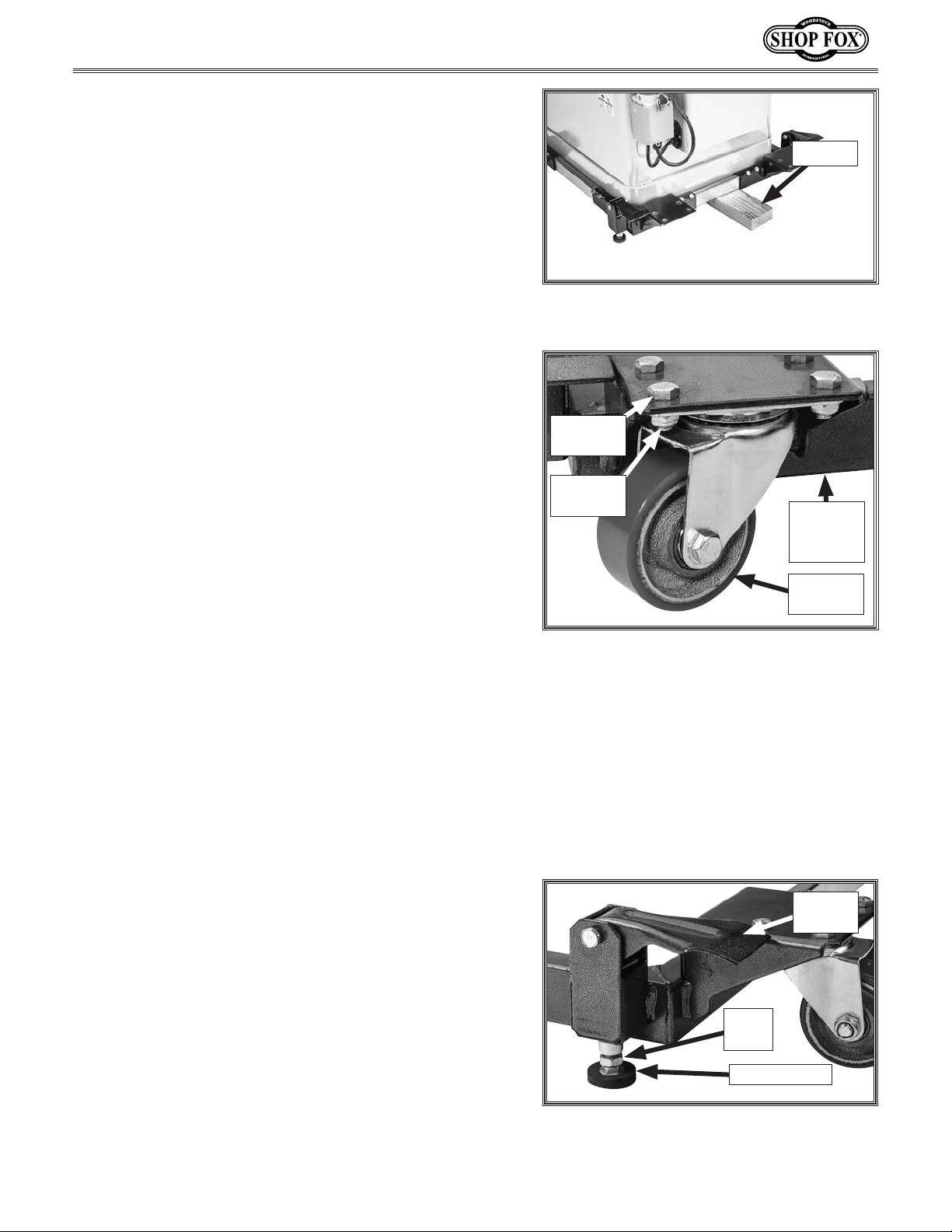
12. With the help of an assistant, tilt machine, and
insert a 2x4 block beneath machine and mobile base
frame (see Figure 19).
13. Attach each swivel caster to corner of assembly
using (4) M8-1.25 x 16 hex bolts and (4) M8-1.25 lock
nuts (see Figure 20).
Note: Patience is required when installing fasteners
inside the bottom of the caster wheels due to space
constraints.
14. With the help of an assistant, tilt machine and
remove 2x4 block from beneath machine and mobile
base frame, and set machine on the floor.
Note: When moving the mobile base, the rubber
feet should not touch the floor. However, when
operating the machine, ensure that the rubber feet
are fixed firmly against the floor to stabilize the
machine.
Adjusting Rubber Feet
The height of the rubber feet can be adjusted to stabilize the machine. To ensure the machine does not move
during operations, always make sure the swiveling caster
wheels (see Figure 21) are not touching the ground before
operating the machine.
12" 2x4
Figure 19. 2x4 Placed beneathe machine
and mobile base frame.
Hex Bolt
(1 of 4)
Lock Nut
(1 of 4)
Front
Corner
Bracket
Swivel
Caster
Figure 20. Swivel caster attached front
corner bracket.
Tool Needed Qty
Open-End Wrench 17mm.......................................1
To adjust rubber foot height, do these steps:
1. Lower swiveling caster to the ground by lifting foot
pedal up (see Figure 21).
IMPORTANT: When moving mobile base, rubber feet
should not touch the floor. Likewise, when operating
the machine, ensure that the rubber feet are fixed
firmly against the floor to provide stability.
2. Loosen hex nut on each rubber foot to allow foot
(see Figure 21) to move up or down as needed, then
re-tighten each hex nut.
3. Press down on foot pedal to raise swiveling casters
1
off ground at least
— If casters do not clear floor by at least
⁄8".
1
⁄8", repeat
Steps 1–2 until they do so.
Foot
Pedal
Hex
Nut
Rubber Foot
Figure 21. Rubber foot adjustment.
-7-
Page 8
Making a Base Plate
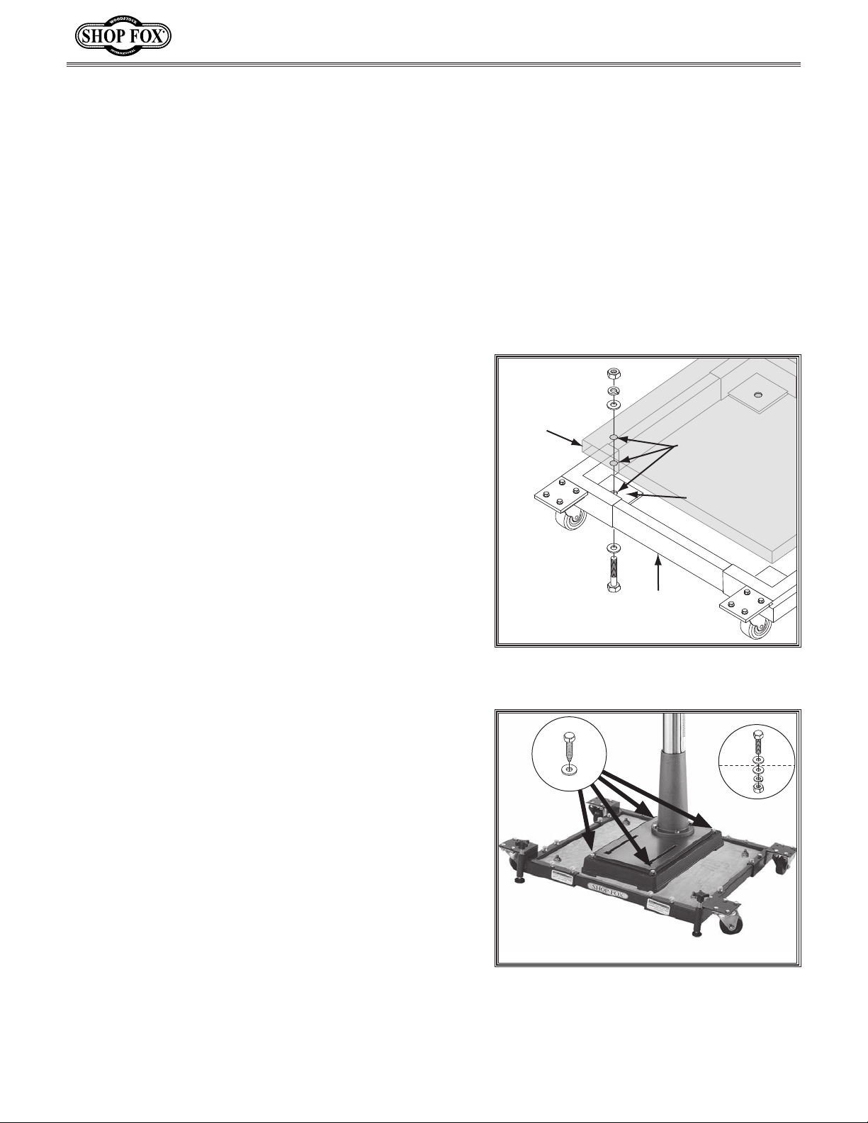
If the footprint of the machine is too small for the mobile
base or the machine doors or fixtures do not clear the
side rails, you can mount it to a base plate, as shown in
Figure 23.
A good quality base plate can increase the standard footprint of machines, such as drill presses, to make them
more stable. The base plate must be at least 1
and made of plywood (do not use OSB, MDF, or particle
board) to hold the weight of the machine.
1
⁄2" thick
D4666 Heavy-Duty Mobile Base
Needed Materials for Base Plate Qty
3
• Plywood
⁄4" x base width x base length ..............2
• Wood Glue ...................................... As Needed
1
• Wood Screws #6 x 1
⁄4" ................................. 24
• Mounting Hardware .................................Varies
To make and use the base plate, do these steps:
1. Glue the two pieces of plywood together, and align
edges and corners so the two boards make one thick
piece.
2. Use wood screws to fasten boards together from both
sides.
Note: Allow 24 hours for the glue to dry before plac-
ing your machine on the base.
3. Refer to Assembly on Page 3 for assembly instructions.
4. Place plywood base plate on assembled mobile base.
5. Drill holes through base plate and bracket plates at
each corner of mobile base.
6. Secure base plate to the mobile base with hex bolts,
hex nuts, flat washers and lock washers, as shown in
Figure 22.
Base
Plate
Mounting
Holes
Metal
Plate
Mobile
Base
Figure 22. Example of mounting base
plate to mobile base.
OR
1
Note: Use 2"–2
⁄4" long hex bolts.
7. Place your machine on base plate, and position
machine close to front or center of mobile base, so
mobile base will not be a tripping hazard.
8. Mount machine to base plate with lag bolts and flat
washers (see Figure 23); or drill holes through base
plate and secure machine with through bolts, flat
washers, and hex nuts.
-8-
Figure 23. Example of drill press mounted
on mobile base, using a base plate for
support.
Page 9
D4666 Heavy-Duty Mobile Base
Using Mobile Base
1. DISCONNECT THE MACHINE FROM POWER!
2. With machine mounted on mobile base, adjust each
rubber foot so it clears floor by at least
Adjusting Rubber Feet for details.
— If the floor is uneven, retract the feet completely
to eliminate the chance of the pads dragging on
the floor.
3. Check to make sure the pathway is clear of all
obstructions.
Before moving the machine and mobile base, check
to make sure the pathway is clear of any hoses, wires,
tools or shop debris. An abrupt impact with an object
in the path of travel can lock a wheel and cause the
machine to fall over, resulting in serious personal
injury. Disconnect the machine from any power
supply or dust collection system before moving.
4. Push machine from the lowest possible point to avoid
tipping it over, and move it to its new location.
Note: The best control is usually achieved by push-
ing on the side with the swivel casters.
— If the machine is large, get an assistant to help
stabilize the machine while it is being moved.
5. Adjust each foot until it touches floor, then lower
each foot at least an additional half-turn. This
ensures major load of machine is on feet rather than
on casters.
6. Check the machine to make sure it is stable in its
new location, and make sure the machine is clear of
any obstructions before reconnecting the power and
turning the machine ON.
1
⁄8". Refer to
Lift heavy equipment carefully and
with the proper equipment. Get assistance if needed to reduce the risk of
serious personal injury.
To avoid serious personal injury, keep
your hands and fingers clear of machine
base and mobile base pinch points
when placing the machine.
To reduce risk of serious injury when
using this mobile base:
1. LOCKING FEET. Do not operate
the machine on the mobile base
unless both mobile base feet firmly
contact the floor and raise the
base enough to disable the casters.
Using the machine on the base
when it is not secured could result
in a loss of workpiece control.
2. TIPPING HAZARD. To avoid tipping
it over, push the machine and
base at the lowest possible point
and have an assistant stabilize the
machine if it is large.
3. PINCH HAZARD. Keep your hands
clear of any potential obstructions
between the machine you are
moving and other equipment or
tables that may protrude into the
path of travel.
4. MACHINE STABILITY. Test for
stability after placing the machine
in its new location. Turn the knobs
down enough to move the feet
against the ground, then push on
the machine at several locations,
making sure it is not off balance.
-9-
Page 10
D4666 Heavy-Duty Mobile Base
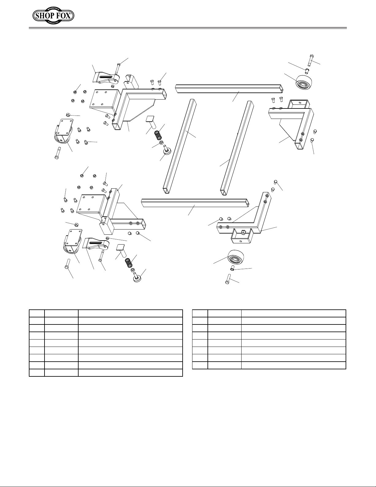
D4666 Parts Breakdown & List
15
12
8
16
15
12
7
16
12
17
12
5
10
3
9
15
11
4
5
5
5
12
14
6
1
12
2
13
12
13
16
7
8
9
17
10
11
12
6
14
13
REF PART # DESCRIPTION REF PART # DESCRIPTION
1 XD4666001 LEFT REAR CORNER BRACKET 10 XD4666010 COMPRESSION SPRING 22 X 1.5 X 61
2 XD4666002 RIGHT REAR CORNER BRACKET 11 XD4666011 ADJUSTABLE FOOT M10-1.5 X 30
3 XD4666003 LEFT FRONT CORNER BRACKET 12 XD4666012 HEX BOLT M8-1.25 X 16
4 XD4666004 RIGHT FRONT CORNER BRACKET 13 XD4666013 SHOULDER BOLT M10-1.5 X 14, 10 X 55
5 XD4666005 RAIL 21" 14 XD4666014 WHEEL BEARING SLEEVE
6 XD4666006 CASTER, 3" FIXED 15 XD4666015 HEX NUT M10-1.5
7 XD4666007 CASTER, 3" SWIVEL 16 XD4666016 LOCK NUT M8-1.25
8 XD4666008 FOOT PEDAL 17 XD4666017 SHOULDER BOLT M8-1.25 X 8, 8 X 50
9 XD4666009 FOOT PEDAL PLUNGER
-10-
Page 11

WARRANTY
Woodstock International, Inc. warrants this equipment to be free of defects from workmanship and
materials for a period of 1 year from the date of original purchase. The liability under this warranty shall
not exceed the purchase price paid for the products and is limited to credit for, or replacement of the
defective part.
We do not warrant or represent that the merchandise complies with the provision of any law or acts,
and buyer assumes all risk and liability resulting from the use of the goods, whether using singly or in
combination with other products.
This warranty does not apply to defects or damages due directly or indirectly from misuse, abuse,
negligence, accidents, repairs or alterations, or lack of maintenance of our products. We shall in no
event be liable for death or injuries to persons or property or for incidental, contingent, special or
consequential damages arising from the use of our products. This disclaimer applies to both during and
after the term of this warranty. Any legal actions brought against Woodstock International, Inc. shall be
tried in the State of Washington, County of Whatcom.
Woodstock International, Inc. reserves the right to implement any changes in specifications or
discontinue any products without notice.
Page 12

 Loading...