

Page 1
Model D4074
Multipurpose Vise
Instruction Sheet
Phone #: (360) 734-3482 • Online Tech Support: tech-support@shopfox.biz • Web: www.shopfox.biz
Specifications
Flat Jaw Size ........................................... 5" x 7⁄8"
Maximum Jaw Opening .......................................5"
Pipe Jaw Maximum Diameter ................................2"
Maximum Throat Depth ....................................2
Mounting Pattern ......................... 4
Base Swivel Capability .................................... 360°
Jaw Rotation Capability .................................. 360°
Weight .....................................................44 lbs.
This vise is not a toy. DO NOT use as a crushing tool
and never clamp a container with compressed or
explosive contents. Serious injury may occur if this
vise is used incorrectly.
7
⁄8"/4-hole square
7
⁄8"
Figure 1. Model D4074.
Placement Location
Consider the existing and anticipated needs, the size of
the material to be held in the vise, and the space for
auxiliary stands, work tables or other machinery when
establishing a location for your new vise. See Figure 2 for
the minimum working clearances.
Workbench Load
The D4074 Multipurpose Vise weighs 44 lbs. Some
workbenches may require additional reinforcement to
support both the vise, the workpiece, and any hammering
or prying forces that may be applied to each.
COPYRIGHT © JULY, 2010 BY WOODSTOCK INTERNATIONAL, INC., REVISED JUNE, 2014 (TS)
WARNING: NO PORTION OF THIS MANUAL MAY BE REPRODUCED IN ANY SHAPE OR FORM WITHOUT
THE WRITTEN APPROVAL OF WOODSTOCK INTERNATIONAL, INC.
17½"
Figure 2. Minimum Clearances.
Printed in China#13033JB
28"
Page 2
Mounting
The multipurpose vise must be mounted to a workbench
to avoid accidental tipping. If you intend to use the vise
for portable applications, mount it to a heavy metal or
plywood base (at least 1" thick) that is wide enough to
prevent tipping or rocking during use, then clamp the
base to a workbench or table.
D4074 - For Models Manufactured Since 12/13
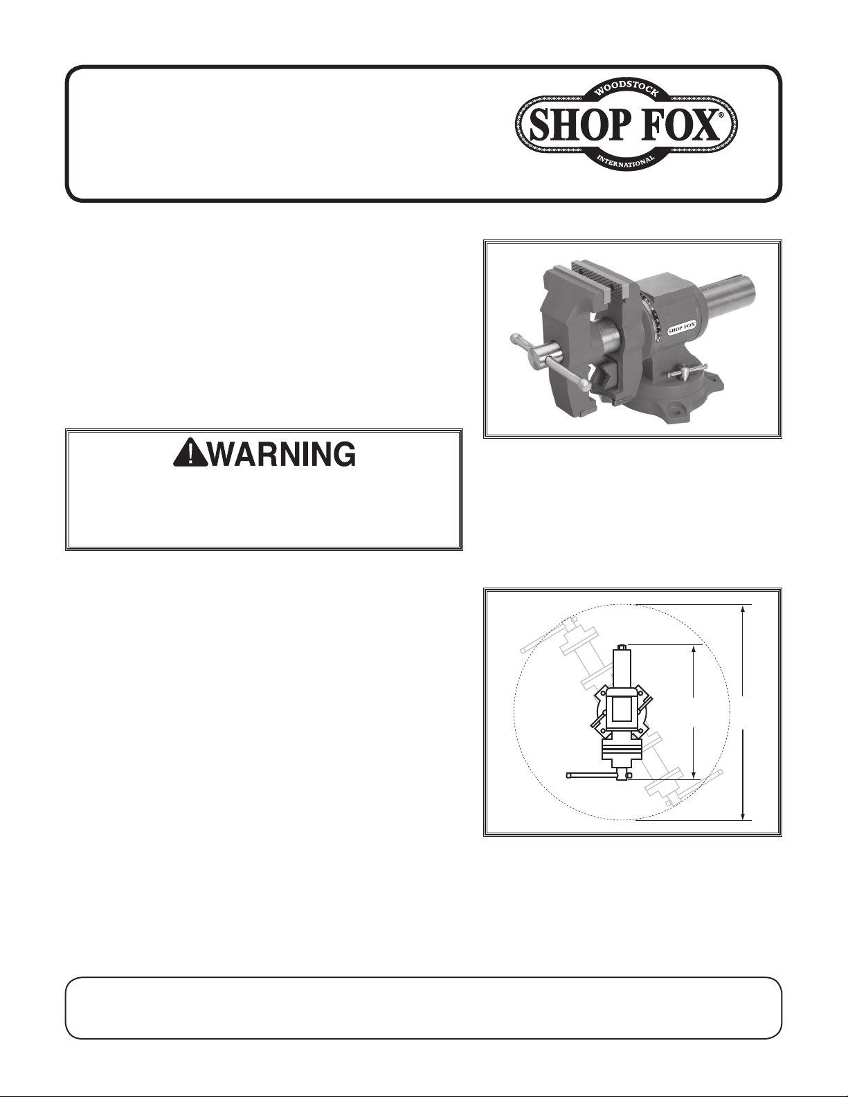
Bolt
Flat Washer
Machine Base
To mount the multipurpose vise, do these steps:
1. Place the vise in its chosen location, making sure
that all four corners of the vise sit flat on the
mounting surface.
2. Transfer the mounting pattern directly from the
vice to the workbench by marking through the vice
mounting holes.
3. Attach the vise to the workbench using one of the
methods outlined below.
Note: DO NOT overtighten the mounting bolts or you
may crack the vise base.
The strongest mounting option is a "Through Mount"
(Figure 3) where holes are drilled all the way
through the workbench, and hex bolts, washers, and
hex nuts are used to secure the vise to the workbench.
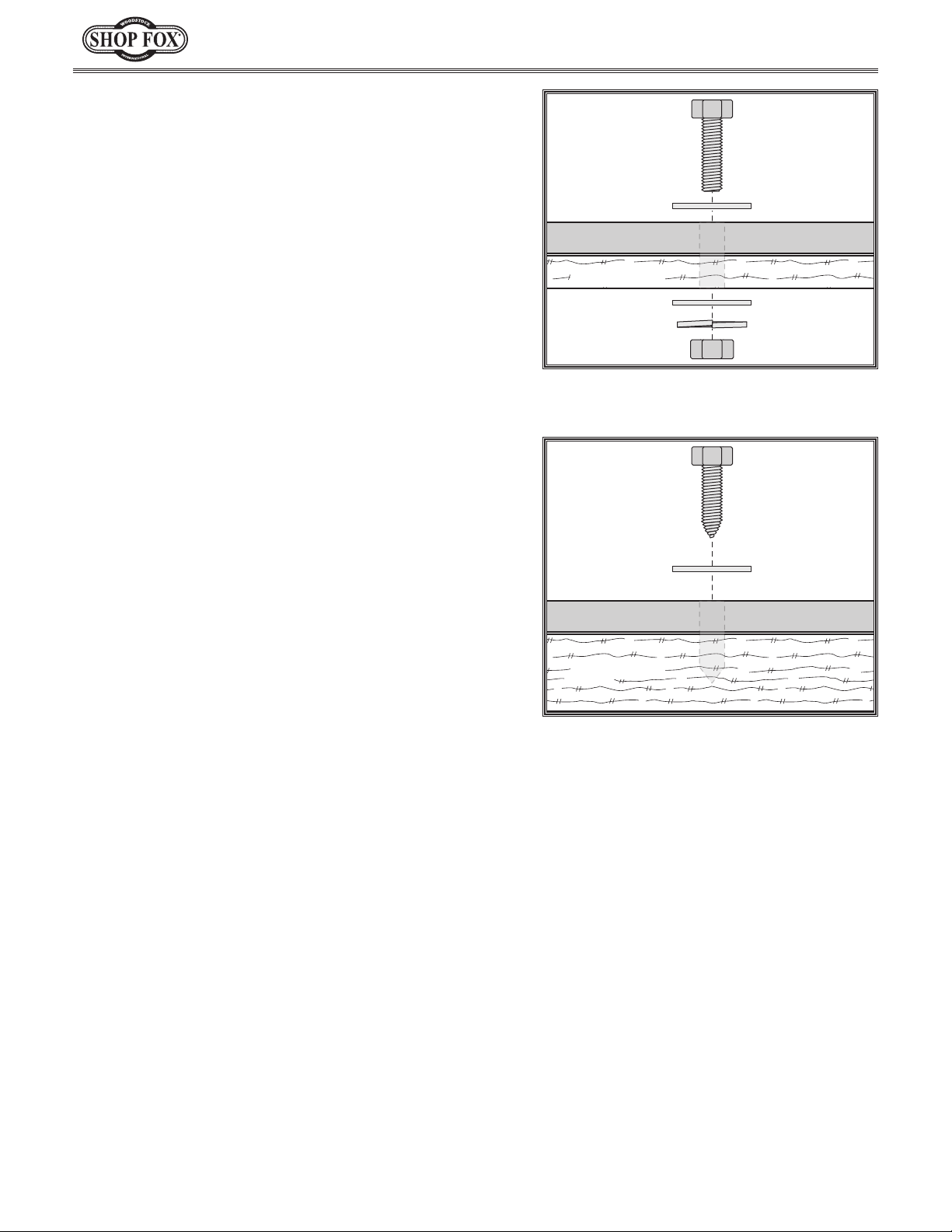
Another option for mounting is a "Direct Mount"
(Figure 4) where the vise is simply secured to the
workbench with a lag screw.
Workbench
Flat Washer
Lock Washer
Hex Nut
Figure 3. Example of a through-mount
setup.
Lag Screw
Flat Washer
Machine Base
Workbench
Figure 4. Example of a direct-mount
setup.
4. Check the stability of the mounted vise to make sure
it can be used safely.
Operations
To maximize the life of your vise, follow this advice:
• Do not use cheater pipes on the handles or hammer
the levers to increase tightening force.
• Do not heat or weld on the vise.
• Do not store the vise in wet or damp locations.
• Only use the anvil for light tapping and workpiece
shaping. Do not use large hammers and avoid
hammering directly on the jaws.
-2-
• Do not pry on clamped materials in
such a way that may bend or break
the vise.
• When loosening the jaws, make sure
your hands will not hit the workpiece,
workbench or vise when the handle
breaks free.
• Every few years, disassemble, clean,
and lubricate the vise using lithium
grease. Otherwise, lubricate as
necessary.
Page 3

D4074 - For Models Manufactured Since 12/13
Features Overview
C
D
H
B
G
A
E
F
Figure 5. Features overview.
A. Anvil Face: Provides a strong and stable
surface for hammering malleable materials
with a small hammer.
B. Rotating Jaws: Allow 360° of movement
and are locked by tightening the jaw.
Scale provides approximate angle readings
through 180°.
C. Standard Jaws: Clamp flat-edged work-
pieces.
D. Main Vise Handle: Used to clamp and lock
the jaws.
E. Base Locking Levers: Allow the base to be
swiveled 360° for maximum flexibility and
locked for stability.
F. Mounting Base: Used to attach the vise to
a workbench or other suitable surface.
G. Pipe Jaws: Clamp pipes and other
cylindrical workpieces. For easier access,
they can be positioned at the top by
rotating the main jaws.
H. Cut Jaws: Clamp irregularly shaped objects
or pieces of pipe that are too short to be
clamped in the pipe jaws.
-3-
Page 4

Parts
D4074 - For Models Manufactured Since 12/13
19
5
4
7
20
21
17
4
2
3
16
5
6
18
17
9V2
23V2
10
24
11
12
13
14V2
6
8
6
22
REF PART # DESCRIPTION REF PART # DESCRIPTION
2 XD4074002 LEADSCREW ASSEMBLY 13 XD4074013 PHLP HD SCR M5-.8 X 30
3 XD4074003 ADJUSTABLE JAW 14V2 XD4074014V2 LOCK NUT M16-2
4 XD4074004 JAW FACEPLATE 16 XD4074016 OUTER V-JAW
5 XD4074005 PHLP HD SCR M6-1 X 14 17 XD4074017 PHLP HD SCR M5-.8 x 10
6 XD4074006 RIVET 2 X 4MM NAMEPLATE, STEEL 18 XD4074018 EXTENTION SCALE
7 XD4074007 BACK JAW 19 XD4074019 CAP SCREW M5-.8 X 12
8 XD4074008 ROTATION SCALE 20 XD4074020 INNER PIPE JAW
9V2 XD4074009V2 LOCK HANDLE V2.12.13 21 XD4074021 INNER V-JAW
10 XD4074010 MAIN HOUSING 22 XD4074022 BASE
11 XD4074011 END CAP 23V2 XD4074023V2 ROTATION PLATE V2.12.13
12 XD4074012 END CAP WASHER 24 XD4074024 CARRIAGE BOLT M10-1.5 X 50
-4-
 Loading...