

Page 1
Model D4041
Miter Saw Stand
Instruction Sheet
Phone #: (360) 734-3482 • Online Tech Support: [email protected] • Web: www.shopfox.biz
Introduction
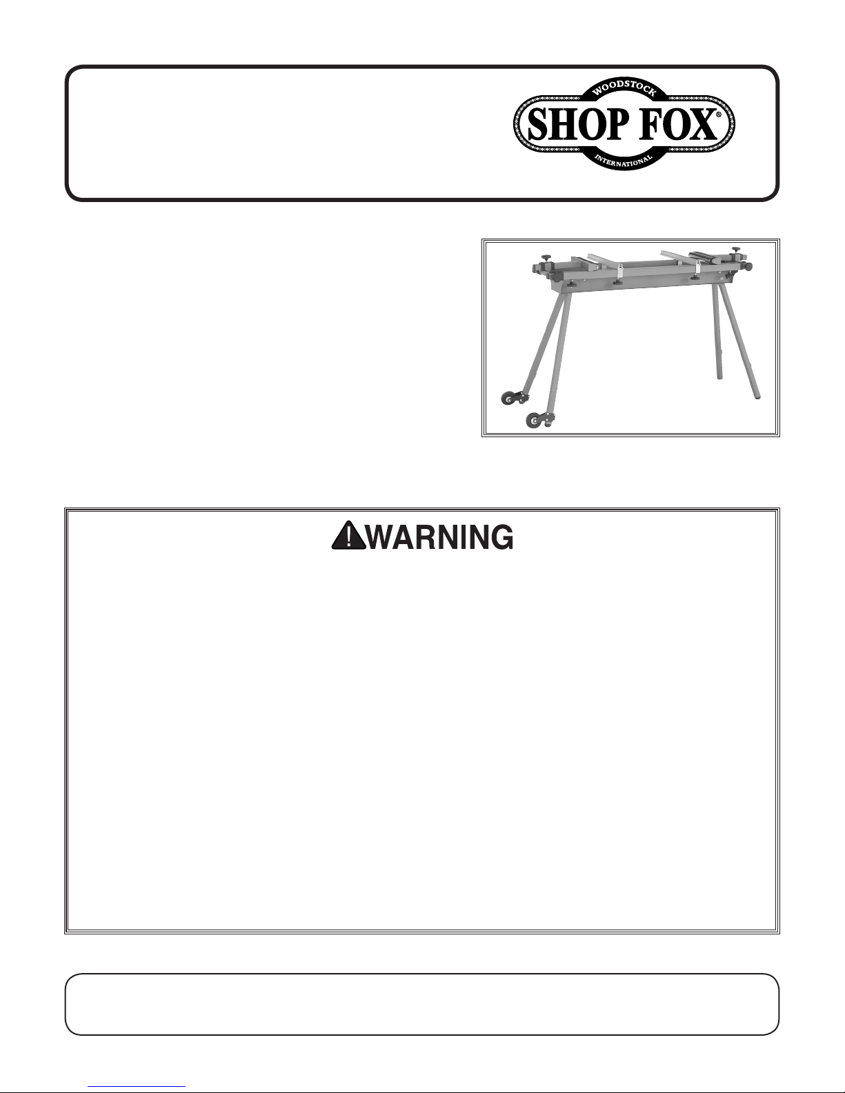
The Model D4041 Miter Saw Work Stand (Figure 1)
features a universal, adjustable T-track mounting system
for securing miter saws without modification. Laterally
and vertically adjustable ball bearing rollers on each
end of the stand support long workpieces. Roller mounts
rotate incrementally for fine height adjustment. Folding
legs and rubber wheels make this work stand portable.
Unpacking
This item was carefully packaged for safe transportation.
If you notice that it was damaged during shipping, please
contact your Shop Fox dealer immediately.
Figure 1. Model D4041.
TO REDUCE THE RISK OF SERIOUS PERSONAL INJURY WHEN USING THIS ITEM:
1. MITER SAW SAFETY. Follow all safety instructions in the miter saw manual.
2. MITER SAW WORK STAND SET UP. Make sure
the leg locking pins are fully snapped into
place before mounting the miter saw.
3. MITER SAW WORK STAND PLACEMENT. Only
operate the miter saw work stand on a hard,
flat, and level surface. DO NOT set up the
miter saw work stand on a soft surface, such
as sand or mud.
4. MITER SAW WORK STAND USAGE. Only use
the miter saw work stand to support a miter
saw. This stand is NOT intended for use as a
ladder or scaffolding.
5. WORKPIECE BALANCE. Use extra support
tables, or get assistance, when working with
large workpieces to prevent the stand from
tipping over.
6. ATTACH MITER SAW SECURELY. DO NOT
operate the miter saw unless it is securely
attached to the miter saw work stand.
7. LOCK WORK SUPPORTS. Tighten lock knobs
to secure the work supports before using the
miter saw work stand.
8. EXPERIENCING DIFFICULTIES. If at any time
you are experiencing difficulties performing
the intended operation, stop using this stand!
Contact Tech Support at (360) 734-3482 for
help.
COPYRIGHT © JULY, 2010 BY WOODSTOCK INTERNATIONAL, INC.
WARNING: NO PORTION OF THIS MANUAL MAY BE REPRODUCED IN ANY SHAPE OR FORM WITHOUT
THE WRITTEN APPROVAL OF WOODSTOCK INTERNATIONAL, INC.
Printed in China#13127TR
Page 2
Inventory
In the event that any nonproprietary parts are missing
(e.g. a nut or a washer), we would be glad to replace
them, or for the sake of expediency, replacements can be
obtained at your local hardware store.
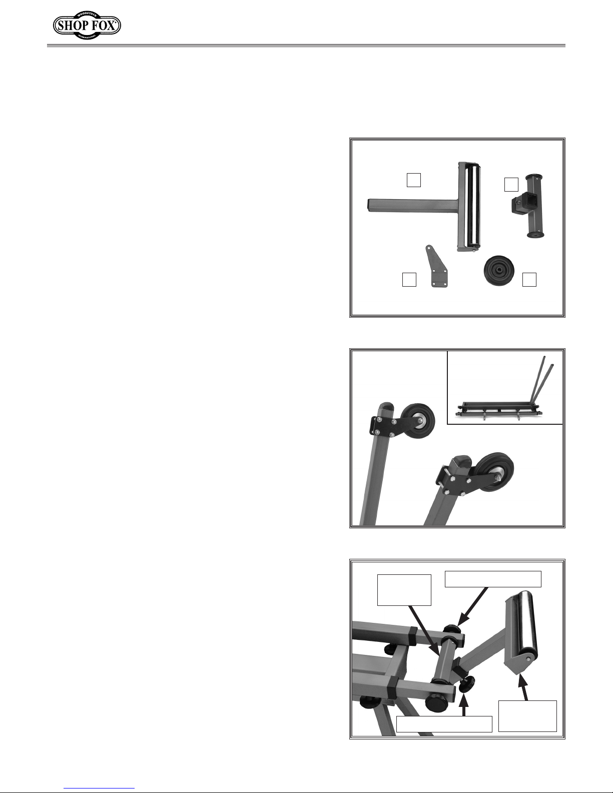
Box Contents: (Figure 2) Qty
A. Stand (not shown) .........................................1
B. Roller Assembly ............................................2
C. Roller Crossbar .............................................2
D. Wheel Brackets ............................................4
E. Wheels ......................................................2
Hardware: Qty
—Support Braces ...........................................2
—Hex Bolts M8-1.25 x 45 .................................2
—Hex Bolts M6-1 x 45 ................................... 12
—Flat Washers 6mm ..................................... 12
—Hex Nuts M6-1 .......................................... 12
—Lock Nuts M8-1.25 .......................................2
—Knobs M8-1.25 x 50 ......................................4
—Knobs M8-1.25 x 20 ......................................2
—Hex Bolts M8-1.25 x 50 .................................4
—Hex Nuts M8-1.25 ........................................8
—Flat Washers 8mm .......................................6
D4041 Miter Saw Stand Instructions
B
C
D E
Figure 2. Model D4041 inventory.
Assembly
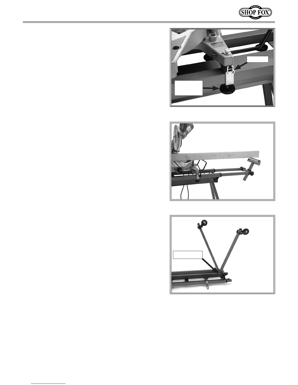
1. Lay the work stand upside down and unfold the top
set of legs (inset in Figure 3). Make sure the locking
pins snap into place.
2. Place a wheel bracket on both sides of the wheel
and thread (1) M8-1.25 x 45 hex bolt through the
assembly (see Figure 3), then secure it with (1)
8mm flat washer and (1) M8-1.25 lock nut.
3. Place each wheel bracket assembly over the stand
leg, thread (4) M6-1 x 45 hex bolts through each
wheel bracket (see Figure 3), and secure them with
flat washers and hex nuts.
4. Unfold the remaining legs; install the support braces
between the legs with the remaining M6-1 x 45 hex
bolts, flat washers, and hex nuts.
5. Place the work stand upright, move the bottom of
the wheels approximately an
tighten the hex nuts.
1
⁄8" above the floor and
Figure 3. Wheel assembly.
Roller
M8-1.25 x 50 Knob
Crossbar
6. Place the roller crossbar between the extension arms
and secure them with the M8-1.25 x 50 knobs, as
shown in Figure 4.
-2-
Roller
M8-1.25 x 20 Knob
Assembly
Figure 4. Support roller assembly.
Page 3
D4041 Miter Saw Stand Instructions
7. Slide the roller assemblies into the crossbars and
secure them with the M8-1.25 x 20 knobs (see Figure
4).
8. Loosen the T-track lock knobs and adjust the T-tracks
to the width of your miter saw, then slide the heads
of two M8-1.25 x 50 hex bolts into each T-track.
9. Place the miter saw over the bolts, and secure each
location with one washer and two hex nuts (see
Figure 5); when securing these, tighten the top hex
nut against the bottom one so they do not work loose
from the vibrations that occur while cutting.
Adjusting Work Stand Extension Arms
1. Slide the extension arms out to their maximum reach
and place a straight 2x4 across the miter saw table
and rollers.
2. Loosen the crossbar knobs and rotate the roller
assemblies until the rollers almost touch the 2x4, as
shown in Figure 6. Then loosen the roller assembly
lock knobs, slide the rollers up to touch the 2x4, and
re-tighten the lock knobs.
T-Track
T-Track
Lock Knob
Figure 5. Mounting the miter saw.
Folding Miter Saw Stand for Storage
1. Remove the support braces, retract the extension
arms and rotate the support rollers flat.
2. Push in the locking pins shown in Figure 7 and fold
the legs up into the stand.
Figure 6. Adjusting the support rollers.
Locking Pin
Figure 7. Folding the miter saw stand.
-3-
Page 4
D4041 Parts
1
2
3
4
5
6
7
8
9
10
11
12
13
14
15
16
17
18
19
20
21
22
23
24
25
26
27
28
29
30
31
32
33
34
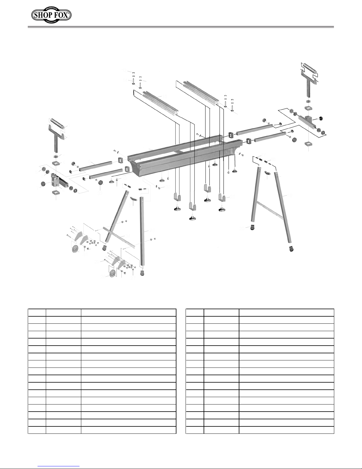
REF PART # DESCRIPTION REF PART # DESCRIPTION
1 XD4041001 ROLLER 18 XD4041018 SMALL AXLE
2 XD4041002 SUPPORT 19 XD4041019 RIGHT LEG
3 XD4041003 END PLUG 20 XD4041020 FOOT
4 XD4041004 BUSHING 21 XD4041021 T-TRACK LOCKING PLATE
5 XD4041005 OUTSIDE GEAR 22 XD4041022 BIG AXLE
6 XD4041006 INSIDE GEAR 23 XD4041023 LEFT LEG
7 XD4041007 LOCK KNOB M8-1.25 X 20 24 XPB71M HEX BOLT M6-1 X 45
8 XD4041008 ROLLER CROSSBAR 25 XD4041025 WHEEL BRACKET
9 XD4041009 EXTENSION ARMS 26 XPW03M FLAT WASHER 6MM
10 XPB06M HEX BOLT M8-1.25 X 12 27 XPN01M HEX NUT M6-1
11 XD4041011 STAND 28 XD4041028 WHEEL
12 XPN03M HEX NUT M8-1.25 29 XPB118M HEX BOLT M8-1.25 X 45
13 XPWF08M FENDER WASHER 8MM 30 XPLN04M LOCK NUT M8-1.25
14 XPB166M HEX BOLT M8-1.25 X 50 31 XPW01M FLAT WASHER 8MM
15 XD4041015 T-TRACK 32 XD4041032 LOCK KNOB M8-1.25 X 50
16 XD4041016 COMPRESSION SPRING 33 XPB03M HEX BOLT M8-1.25 X 16
17 XD4041017 PIN 34 XD4041034 SUPPORT BRACE
D4041 Miter Saw Stand Instructions
-4-
 Loading...