

Page 1
Model D3699
Fully Enclosed Blade Cover For
W1806
Instruction Sheet
Phone #: (360) 734-3482 • Online Tech Support: tech-support@shopfox.biz • Web: www.shopfox.biz
Inventory
Descriptions (Figure 1) Qty
A. Blade Cover Frame Assembly ............................1
B. Extension Tube .............................................1
C. Support Frame .............................................1
D. Right Blade Cover .........................................1
E. Left Blade Cover ...........................................2
F. Fasteners (Not Shown):
— For Frame:
Lock Lever Assembly .................................1
Cap Screws M8-1.25 x 25 ............................4
Lock Washers 8mm ...................................4
Flat Washers 8mm ....................................4
Set Screws M6-1 x 12 ................................4
Knurled Knob Screws M6-1 x 12 ....................4
Lock Washers 6mm ...................................4
Flat Washers 6mm ....................................4
— For Blade Cover Frame Assembly:
Knob Screw M6-1 x 15 ...............................1
Hex Nut M6-1 ..........................................1
Phillips Head Screws M4-.7 x 10 .................. 12
Figure 2. Model D3699 Fully Enclosed
Blade Cover.
For cutting operations that cut completely through the workpiece, always
make sure the blade guard is in good
working order and is properly positioned over the blade. Otherwise,
unintentional contact with the spinning
blade could occur, causing laceration or
amputation.
A
E
Figure 1. Model D3699 shipping inventory.
WARNING: NO PORTION OF THIS MANUAL MAY BE REPRODUCED IN ANY SHAPE OR FORM WITHOUT
B
D
FOR MODELS MANUFACTURED SINCE 3/10
COPYRIGHT © JUNE, 2010 BY WOODSTOCK INTERNATIONAL, INC.
THE WRITTEN APPROVAL OF WOODSTOCK INTERNATIONAL, INC.
C
DO NOT use the Model D3699 without
an adequate dust collection system
that provides 150 CFM at the connection point of the cover frame. Failure
to use a adequate dust collection system can result in short and long-term
respiratory illness.
Printed in Taiwan#13011TS
Page 2
D3699 Blade Cover Instructions (Mfg. Since 3/10)
Assembly
Tools Needed Qty
Additional People ....................................At Least 2
Hex Wrenches 3 & 6mm ................................ 1 Each
Wrench 10mm ...................................................1
Phillips Screwdriver #2 .........................................1
Level ..............................................................1
To assemble and mount the blade cover assembly, do
these steps:
1. DISCONNECT SAW FROM POWER!
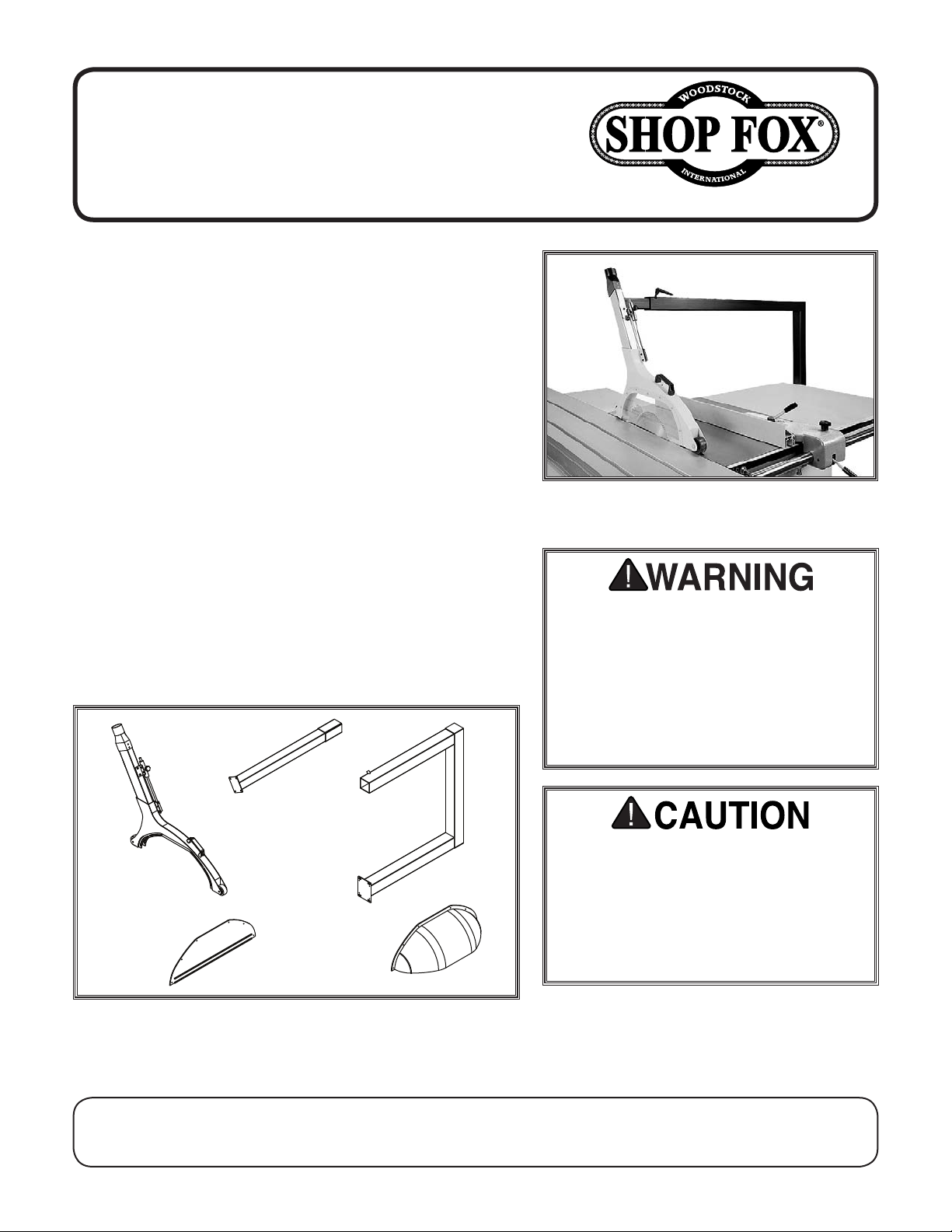
2. Connect the extension tube to the blade cover
frame assembly with the (4) M6-1 x 22 knurled knob
screws, 6mm lock washers, and 6mm flat washers, as
shown in Figure 3.
3. Extend the cover frame assembly all the way, then
tighten the lock knob shown in Figure 3 to keep it
that way.
4. Remove the extension wing from the table saw, and
make sure the saw table is level.
5. Insert the extension tube into the support frame,
have two other people help align the mounting holes
in the frame mounting plate with the four pre-drilled
holes in the table saw cabinet.
Lock
Knob
Extension
Tube
Figure 3. Extension tube attached to the
cover frame.
Set
Screw
Cap
Screw
6. Install and hand-tighten the (4) M8-1.25 x 25 cap
screws, 8mm lock washers, and 8mm flat washers to temporarily hold the assembly in place (see
Figure 4).
7. Install the (4) M6-1 x 10 set screws into the sup-
port frame mounting plate, then, using the level on
top of the frame, thread the set screws in or out to
bring the frame level with the table saw. Fully tighten the cap screws to secure the setting.
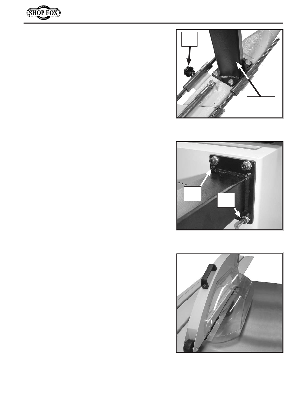
8. Attach the flat blade cover to the cover frame side
that is farthest from the support frame with (7)
M4-.7 x 8 Phillips head screws.
9. Secure the bubbled blade cover with (4) M6-1 x 12
Phillips head screws, 6mm lock washers, and 6mm
flat washers, as shown in Figure 5.
10. Loosen the lock knob you tightened in Step 3 to
allow the blade cover to float freely over the blade.
Your Model D3699 Fully Enclosed Blade cover is now ready for use!
Figure 4. Attaching the support frame to
the table saw cabinet.
Figure 5. Blade covers installed.
-2-
Page 3

D3699 Blade Cover Instructions (Mfg. Since 3/10)
101
102
103
104
105
106
107
108
109
110
111
112
113V2
114V2
115V2
116
117
118
119
120
121V2
122
123
124
125
126
V2
127
129V2
131
132
133
134
135
136
137
138
139
140
141
142
143
144
145
146
147
148
149
150
151
152
153V2
154
110
104
105
106
122
141
108
109
Parts Diagram
-3-
Page 4

D3699 Blade Cover Instructions (Mfg. Since 3/10)
REF PART # DESCRIPTION REF PART # DESCRIPTION
101 XD3699101 GUIDE ROD 127 XPLN04M LOCK NUT M8-1.25
102 XD3699102 GUIDE ROD BUSHING 129V2 XD3699129V2 RIGHT BLADE COVER V2.03.10
103 XD3699103 GUIDE ROD SLEEVE 131 XPSS04M SET SCREW M6-1 X 12
104 XPBHS09M BUTTON HD CAP SCR M6-1 X 12 132 XPW01M FLAT WASHER 8MM
105 XPLW03M LOCK WASHER 6MM 133 XPLW04M LOCK WASHER 8MM
106 XPW03M FLAT WASHER 6MM 134 XPCAP31M CAP SCREW M8-1.25 X 25
107 XD3699107 GUIDE ROD MOUNTING BRACKET 135 XD3699135 EXTENSION TUBE
108 XPBHS11M BUTTON HD CAP SCR M6-1 X 10 136 XD3699136 SUPPORT FRAME
109 XPLW03M LOCK WASHER 6MM 137 XD3699137 LOCK LEVER ASSEMBLY
110 XPW03M FLAT WASHER 6MM 138 XPW03M FLAT WASHER 6MM
111 XD3699111 KNOB SCREW M6-1 X 15 139 XPLW03M LOCK WASHER 6MM
112 XD3699112 DUST CHUTE 140 XD3699140 KNURLED KNOB SCREW M6-1 X 12
113V2 XD3699113V2 DUST SEAL 90MM THIN V2.03.10 141 XD3699141 PIVOT BOLT
114V2 XD3699114V2 DUST SEAL 40MM V2.03.10 142 XD3699142 TOP SLEEVE COVER
115V2 XD3699115V2 DUST SEAL 90MM THICK V2.03.10 143 XD3699143 SPRING SLEEVE
116 XPBHS05M BUTTON HD CAP SCR M6-1 X 20 144 XD3699144 SPRING ROD SCREW
117 XPSS02M SET SCREW M6-1 X 6 145 XD3699145 SPRING ROD
118 XD3699118 GUIDE ROD SLEEVE BRACKET 146 XD3699146 COMPRESSION SPRING
119 XPCAP11M CAP SCREW M8-1.25 X 16 147 XD3699147 BOTTOM SLEEVE COVER
120 XD3699120 COVER HANDLE 148 XD3699148 CUSHION
121V2 XD3699121V2 LEFT BLADE COVER V2.03.10 149 XPCAP13M CAP SCREW M8-1.25 X 30
122 XPS38M PHLP HD SCR M4-.7 X 10 150 XPN03M HEX NUT M8-1.25
123 XPB28M HEX BOLT M8-1.25 X 60 151 XPCAP11M CAP SCREW M8-1.25 X 16
124 XD3699124 CASTER 152 XPRIV004M STEEL BLIND RIVET 4 X 10MM
125 XD3699125 CASTER BUSHING 153V2 XD3699153V2 DUST PORT 2-1/2" V2.03.10
126V2 XD3699126V2 BLADE COVER FRAME V2.03.10 154 XPN01M HEX NUT M6-1
Parts List
-4-
 Loading...