

Page 1

Auto Lensmeter
SLM-5000
Operations Manual
<Important>
Read this manual thoroughly before use.
Keep this manual on hand at all times.
RB-473-B02M
Page 2
INTRODUCTION
This manual provides you information on correct handling and operational procedures as well as safety
considerations pertinent to the SLM-5000.
Before carrying out any measurements, read the instructions thoroughly so that effective operation is
ensured. As this continues an important reference and user guide, be sure to keep it on hand at all times.
NOTE
(1) The information contained in this manual is subject to change without notice.
(2) While reasonable efforts have been made in the preparation of this document to ensure its accuracy,
you should contact your local distributor immediately, if any queries arise due to editorial errors or
omissions etc.
(3) If you find any imperfect collating or missing pages, contact your local distributor for replacement.
General definitions of safety symbols are indicated below.
Personal injury or physical damage may occur when this warning is
ignored.
General warning. Caution. Risk of danger.
1
RB-473-B02M
Page 3
SAFETY CONSIDERATION
General Precautions
SLM-5000 is NOT a medical device.
Fingerprints or dust on the optical parts such as lenses may affect the measurement accuracy. Always
avoid touching such parts with fingers and keep away from dust getting on them.
When fingerprints or dust are attached onto such parts, gently wipe them with the supplied dust cloth.
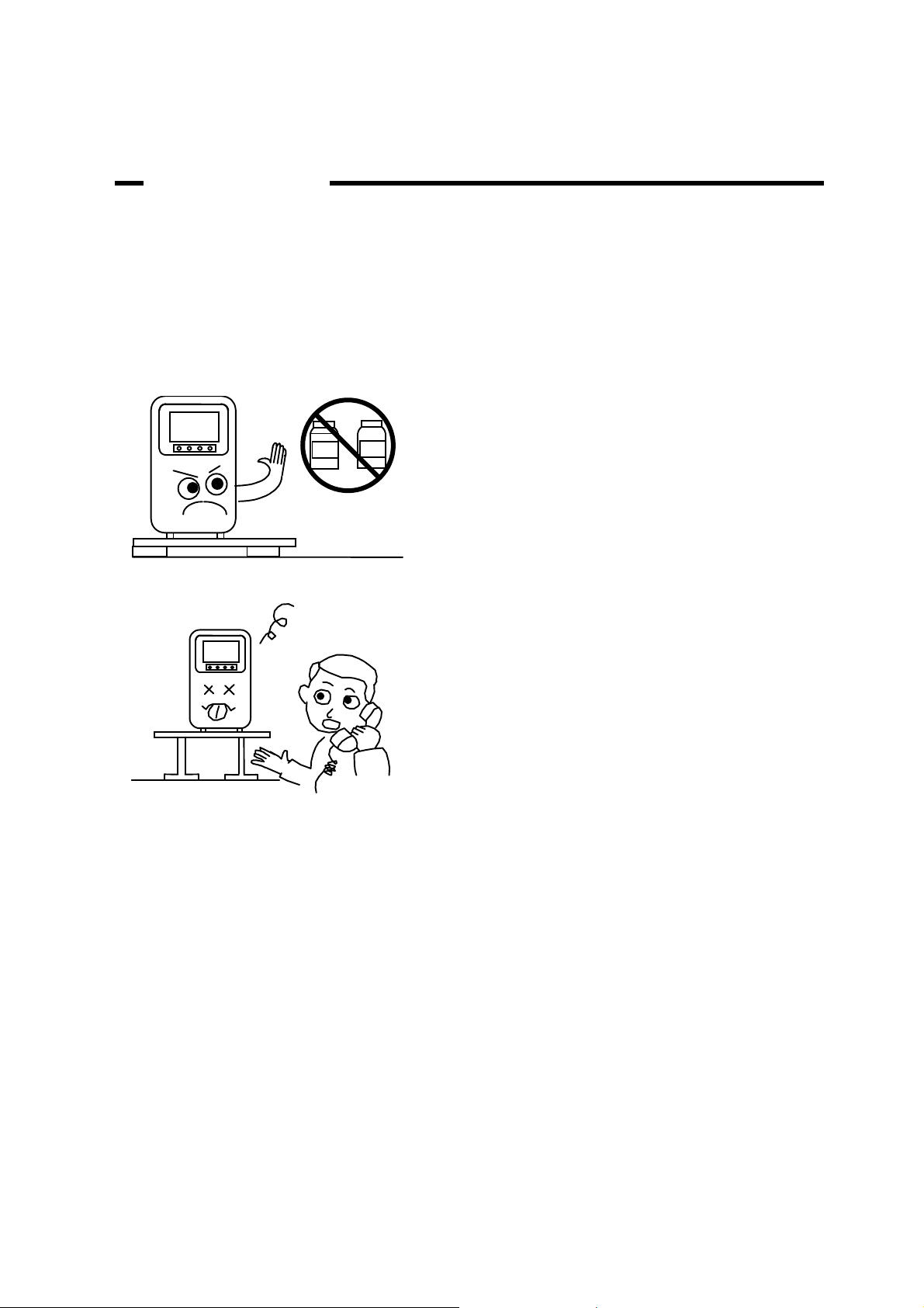
When water or any liquid gets on the instrument, or
when any foreign matters gets inside the instrument,
unplug the power cord immediately and contact your
local distributor.
In case of occurrence of abnormality (noise or smoke),
unplug the power cord immediately and contact your
local distributor. Using the instrument in such a
condition may cause fire or physical damage.
Never dismantle the instrument. Fire or physical
damage may result.
In case of malfunction, never try to repair by yourself.
Unplug the power cord immediately and contact your
local distributor.
2
RB-473-B02M
Page 4
Precautions on power source
The power cord must be grounded at all time.
Avoid damaging the power cord (such as bending it in an extremely small size, pulling, placing a
heavy object on it). When the power cord is damaged (breaks, damage of cover, etc), replace it to a
new cord to prevent any electric shock or fire from ocurring.
Insert the power cord firmly into the outlet and the instrument. If not, fire or electric shock may occur.
Keep the power cord clean without any dust or oil on it. The dirty terminal may cause malfunction or
fire.
When the power cord becomes hot after used, check for the dirt at the terminal part. If you find no dirt,
replace the power cord to a new cord. The dirty terminal may cause malfucntion or fire.
Always use SLM-5000 with the rated powe voltage. Using the instrument out of the rated voltage
range may cause malfunction or fire.
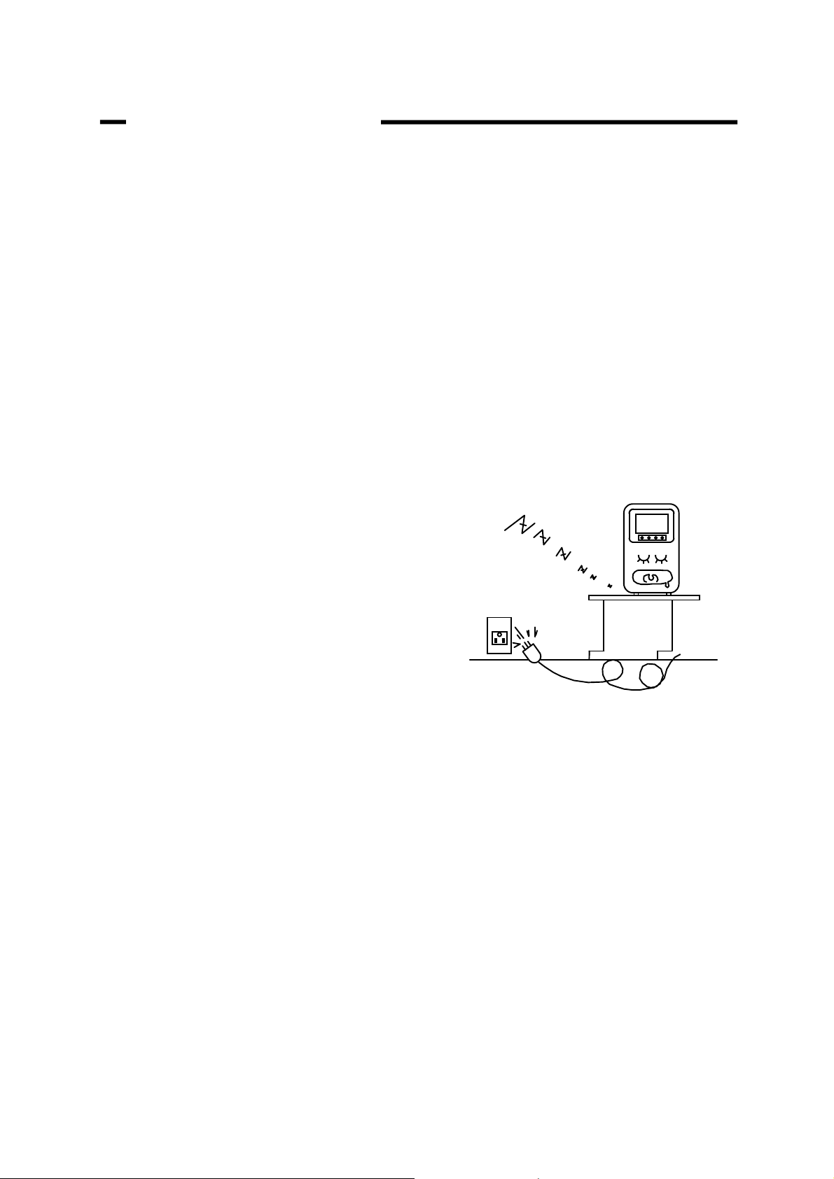
When pluging and unpluging the power cord,
always hold the plug.
Do not touch the plug when your hands are wet.
When the instrument is not used for a long time,
unplug the power cord from the outlet.
3
RB-473-B02M
Page 5

Contents
1. Parts Identification.....................................................................................................................5
1.1. Overview ...............................................................................................................................5
1.2. Accessories...........................................................................................................................6
2. Installation Environment............................................................................................................ 7
3. Safeguard Summary................................................................................................................. 8
4. Measurement Screen................................................................................................................ 9
4.1. Switch Function.....................................................................................................................9
4.2. Each Setting........................................................................................................................10
4.2.1. Set up Screen............................................................................................................. 10
4.2.2. ID Screen.....................................................................................................................11
4.2.3. RS 232C Screen......................................................................................................... 12
4.2.4. Date/Time Screen.......................................................................................................13
5. How to operate the lensmeter................................................................................................. 14
5.1. Lens holder..........................................................................................................................14
5.2. Lens plate............................................................................................................................14
5.3. Marking lever.......................................................................................................................15
5.3.1 How to operate............................................................................................................ 15
5.3.2. Replacement of marking pen...................................................................................... 16
5.4. Printer..................................................................................................................................17
5.4.1 How to operate............................................................................................................ 17
5.4.2. Type of print out.......................................................................................................... 17
5.4.3. Setting and replacement of printer paper................................................................... 18
6. Measurement.......................................................................................................................... 19
6.1. Check before Measurement................................................................................................19
6.2. Single Lens..........................................................................................................................20
6.3. Frame Lens.........................................................................................................................22
6.4. Multifocal Lens ....................................................................................................................23
6.5. Progressive Lens................................................................................................................24
6.6. Auto memory function.........................................................................................................27
6.7. Power saving function.........................................................................................................27
6.8. Contact lens ........................................................................................................................28
6.8.1. Preparation ................................................................................................................. 28
6.8.2. How to measure.......................................................................................................... 28
7. Marking.................................................................................................................................... 29
Lens without Astigmatism............................................................................................................29
7.2. Lens with Astigmatism.........................................................................................................29
7.3. Marking of prism Lens.........................................................................................................30
8. Error Messages.......................................................................................................................31
8.1. Descriptions.........................................................................................................................31
8.2. Measures taken for the errors.............................................................................................31
9. Specification............................................................................................................................ 32
10. Applicable Laws and Standards.............................................................................................. 32
4
RB-473-B02M
Page 6
1. Parts Identification
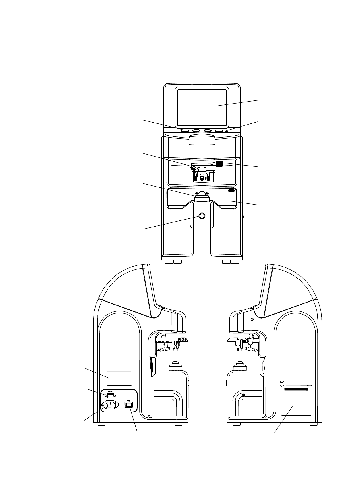
1.1. Overview
Operation switches
Lens holder
Lens stand
Memory/Add switch
Color LCD monitor
Indicator
Marking lever
Lens plate
Rating nameplate
RS-232C terminal
Power inlet
Power switch
5
Printer
RB-473-B02M
Page 7

1.2. Accessories
When you unpack the box, please check the followings are all packed without any damages.
Contact your distributor if any accessories are missing or damaged.
Power cord
Contact lens stand
Rolls of printer paper
Printer shaft
Dustproof cover
Dust cloth
Operations manual
Marking pen (1set)
Filing soft
6
RB-473-B02M
Page 8
Dust
2. Installation Environment
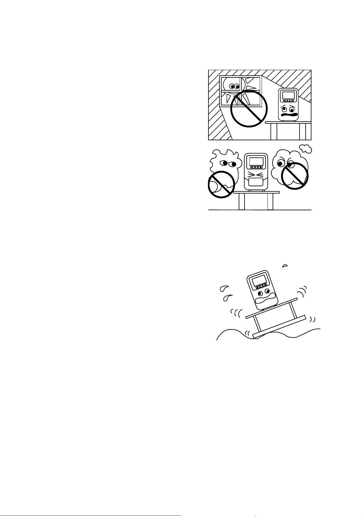
1) Do not expose the optic parts, i.e. lens stand, directly to
sunlight or bright light from other sources.
Strong light or glare to the instrument may cause the
failure of measurement.
2) Do not install the instrument in places where either dust
or rubbish may accumulate.
3) Environments with extremes in heat and humidity
should also be avoided.
Temperature range for use: 10C ~ 40C
Temperature range for storage: -10C ~ 60C
Humidity range for use/storage: 70%HR (no dew condensation allowed)
4) Keep away from inflammable or explosive gases as well as storage areas of medical supplies and
chemicals.
5) Keep awa y from sites that experience strong vibrations
or sudden shocks.
6) Malfunction is likely to occur if the instrument is not
properly stabilized of accidentally overturns. To prevent
internal/external damage caused by sudden impact,
install the instrument on a surface that is solid and
secure. Do not store in high, ‘out of reach’ places.
Gases
7
RB-473-B02M
Page 9
3. Safeguard Summary
1) Ensure the instrument is properly grounded when connected to the power source.
2) Do not touch or allow dust to settle on the optical parts (i.e. lenses), as their measuring accuracy could
be adversely affected and incorrect value may result.
3) If the surfaces of the measuring unit and main unit
including the operation switches are dirty, gently
wipe with a dry cloth. For hard to remove stains, a
damp cloth or neutral cleanser is recommended.
4) SLM-5000 is a precision optical instrument. Handle
with care at all times, making sure not to
accidentally drop it.
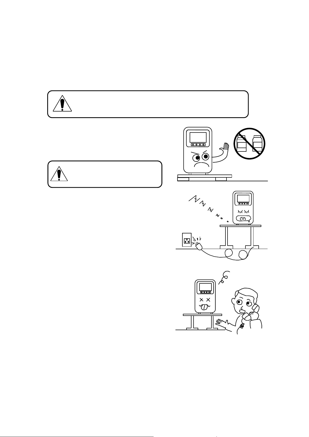
5) If the instrument is not to be used for any length of
time, remove the power cord from the outlet.
6) When not in use, the instrument should be protected
with the provided dustproof cover.
7) If the instrument fails to function properly, do not
attempt to perform internal service or adjustment.
Contact immediately your nearest registered agent,
distributor or retail outlet.
When dust or fingerprints appear, use the supplied dust cloth or a soft
cloth to gently wipe off the build-up. Take great care when cleaning these
parts, as they are particularly sensitive and fragile.
At no time use organic solvents
which will damage the water based
paint finish of the instrument.
8
RB-473-B02M
Page 10
Measuring
Marking OK
C A Px Py
0.00
0
40
Prism value: X direction
Prism value: Y direction
Measurement increment
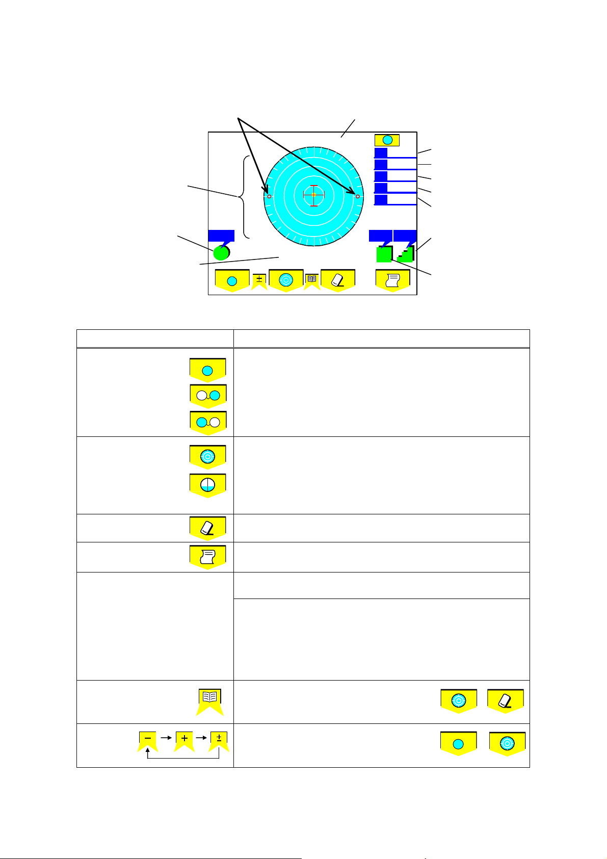
4. Measurement Screen
Measurement area
Error message displa y area
4.1. Switch Function
Axis angle marks
Abbe number
Abbe
Alignment status/
Name Description
Operation mode display area
S
S
0.00
Spherical value
Cylindrical value
Axis angle
I 0.00
U 0.00
Cyl Step
±
.
25
S
Cylindrical sign
designates a type of the lens to be measured:
S
LENS switch
L
a single lens
R
a lens for a right eye
a lens for a left eye
switch the measurement mode:
Measurement selection
switch
a single focal lens measurement
<single/progressive
lens>
a progressive lens measurement.
CLEAR switch erases the data stored in memory.
PRINT switch prints out the data.
stores the measurement data in memory when a single focal lens is
measured.
determines the measurement value of the far point when the
Memory/Add switch
addition is measured.
determines the far point for auto measurement of the progressiv e
lens.
For the manual measurement, determines the measurement
positions and values for the far and near points.
MENU switch
Cyl switch
corresponds to pressing two switches shown
on the right at the same time. Shift to and
change of each Set up item.
changes the symbol of cyl in the order of
, , and when two switchs are pressed
together.
9
S
RB-473-B02M
Page 11
Selects whether to display the automatic assessment gauge of the near point
Adjustment
Off
On
On
Normal
On
Step
Lens Switch
Prog Auto
Prism Graph Print
F/N.AT
N.AT Manual
EN ES IT PT DE FR
Ray Language
Brightness
3Min
50%
d
ID
ID Screen
2/2
20 30 40 50 60
4.2. Each Setting
4.2.1. Set up Screen
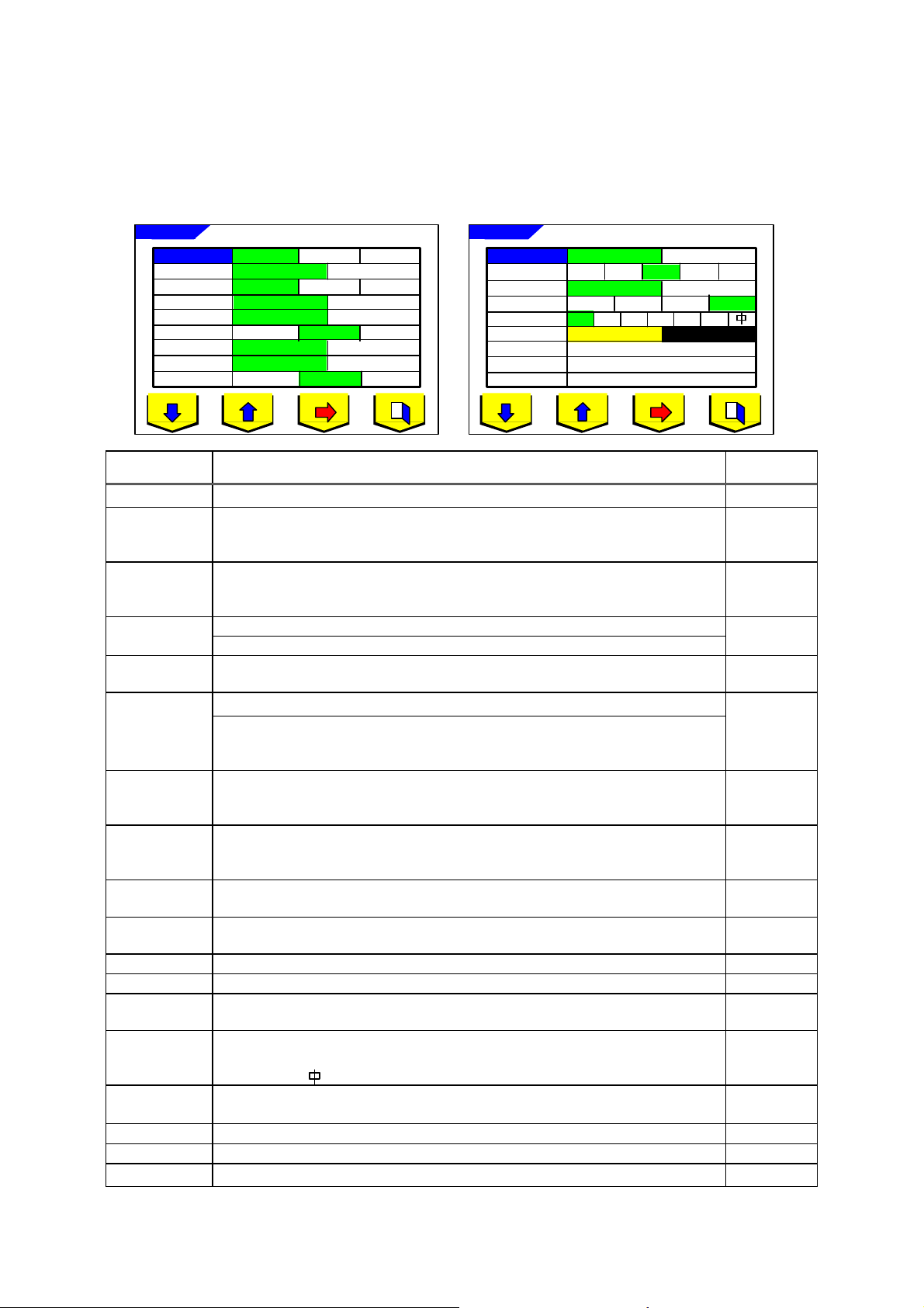
You can set each measurement condition in the Set up screen.
Set up
Lens
Auto Memory
ADD Measure
Prog. Graph
0.25
S/R/L
Off
0.12
H Cont S Cont
Off
Off
Off
X-Y
1/2
0.01
R/L
On
P-B
Item Description
Step
Selection of the increment in diopter. <0.25 / 0.12 / 0.01>
Selection of a lens switch function
Lens Switch
S/R/L : Single Lens / Lens for a right eye / Lens for a left eye
R/L : Lens for a right eye / Lens for a left eye
Setting of the lens type to be measured
Lens
<Normal: a lens for glasses / H Cont: hard contact le ns / S Cont: soft contact
lens>
Auto Memory
Prog Auto
Selection of automatic memory in case of Marking OK.
On/Off
Selects whether to perform the automatic judgment for progressive lens.
<Off: not perform / On: perform>
Selection of automatic/ manual assessment of far point and near point
ADD
Measure
Auto-memory both of a far and a near points (F/N.AT)
Auto-memory only a near point (N.AT)
Memory manually (Manual)
Set up
Prism(mm)
Abbe
Stand by
RS 232C
Date/Ti me
Off
e
Off
RS 232C Screen
Date/Time Screen
5Min
On
10Min
Initial
Setting
0.25
S/R/L
Normal
Off
Off
N.AT
Prog. Graph
Graph Print
Prism
Prism(mm)
Abbe
Ray
Stand by
Language
Brightness
ID
RS 232C
Date/Time
when the progressive lens is measured.
<Off: not displayed / On: displayed>
Selects whether to print the automatic assessment gauge for near point after the
progressive lens is measured.
<Off: not printed / On: printed>
Selects whether to display prism values, and which unit is used if displayed.
<Off: not displayed / X-Y: X-Y display / P-B: prism value - base direction>
Selects whether to display the prism value of X-Y direction in mm.
<Off: not displayed / On: displayed>
Selects Abbe number of the lens measured<20 / 30 / 40 / 50 / 60>
Selects the reference wavelength of measurement <e: e line / d: d line>
Sets how long it takes until power saving function is activated.
<Off: zero / 3Min: 3 minutes / 5Min: 5 minutes / 10Min: 10 minutes>
Selection of language displayed on the screen
EN:English FR:French ES:Spanish IT:Italian PT:Portuguese
DE:German : Chinese
Brightness adjustment of the screen
0 ~ 100% (step: 5%)
Switch to ID screen
Switch to RS 232C screen
Switch to Date/Time screen
10
Off
Off
X-Y
Off
40
e
10Min
EN
value
-
-
-
RB-473-B02M
Page 12
m
Screen (1)
ID
m
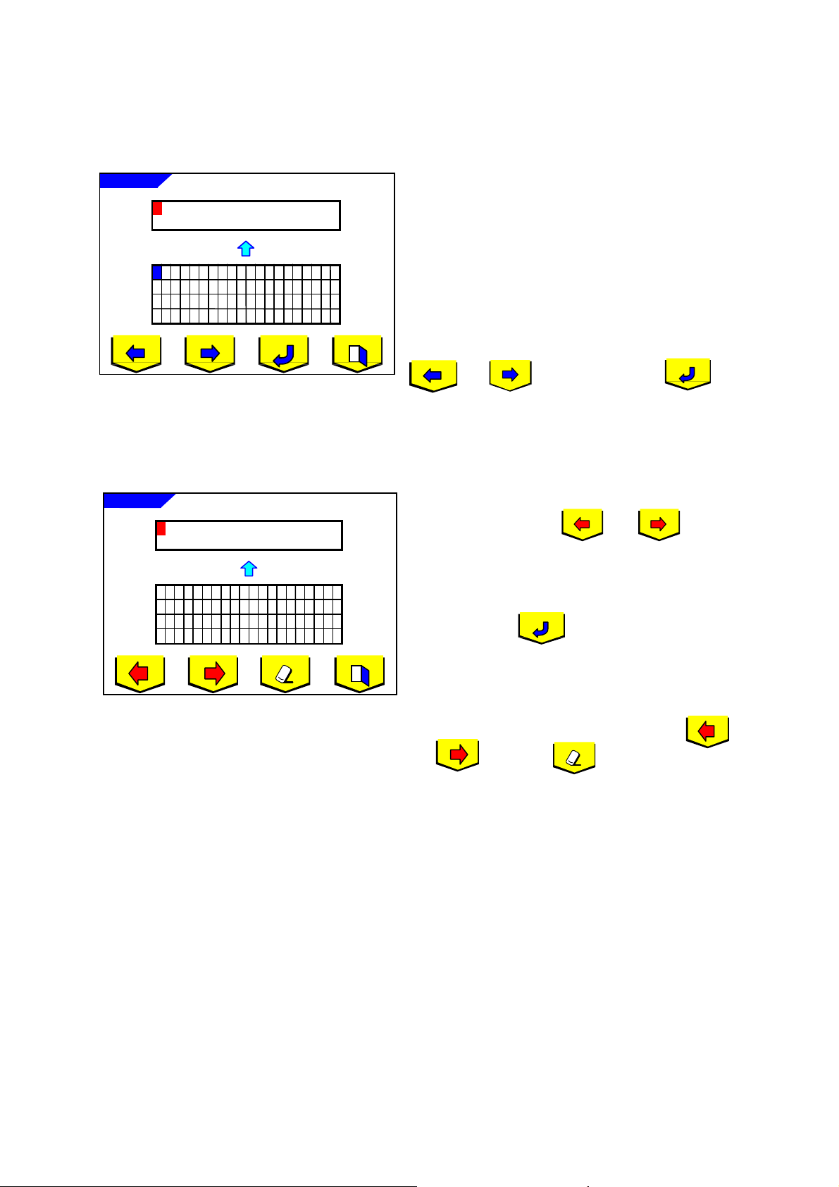
4.2.2. ID Screen
This screen allows you to create the data that would
ID
A
BCDEFGHIJKLMNOPQRST
U
V
W
XYZ abcdefghijkl
n
opqrstuvwxyz012345
6
789 !"&'()*+,- ./: ;=
Screen (2): Memory/Add switch is pressed
A
BCDEFGHIJKLMNOPQRST
U
V
W
XYZ abcdefghijkl
n
opqrstuvwxyz012345
6
789 ! "&'()*+,- ./:;=
always appear on the printout such as a store name or
messages:
Screen (1): for writing the information
Screen (2): for changing and erasing the
information
(during Memory/Add switch pressed).
In the Screen (1), select letters and symbols using
and , and enter them with .
Any changes made will overwrite the original letters
and symbols.
To make some changes, press Memory/Add switch to
call up Screen (2). Using and , move
the cursor to the letter or symbol you wish to change.
Then, release Memory/Add switch to return to the
Screen (1). Select the letter or symbol you wish to
change and press .
To erase the letters or symbols selected, press Memory/
Add switch to call up Screen (2). Move the cursor to
the letters or symbols you wish to erase using
and , and press .
11
RB-473-B02M
Page 13
Data Out
Auto Manual
Print
Stop Bit
NB Bit
RS 232C
1
8
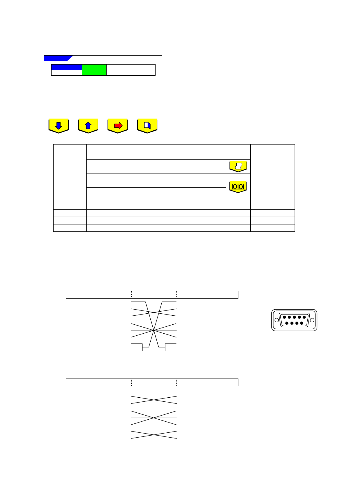
4.2.3. RS 232C Screen
BaudRate
Parity
Item Description Initial Setting
Data Out
BaudRate
NB Bit
Parity
Stop Bit
<Signal names and connection>
Connect each connector of the serial interface as shown below. Connection shall be made to a CE-mark
approved instrument.
[Connection sample 1]
[Connection sample 2]
38400
None
Print print out from the build-in printer
Manual
Auto
Transfer rate
Character length (data bit)
Parity check
Stop bit
D-Sub 9pin(female) D-Sub 9pin(female)
D-Sub 9pin(female) D-Sub 9pin(female)
9600
measurement values are output from RS
232C terminal using the switch.
measurement values are continuously
output from RS 232C terminal.
SLM-5000
SLM-5000
2400
How to output the data Icon
Connection PC
1
2
3
4
5
6
7
8
1
2
3
4
5
6
7
8
1
2
3
4
5
6
7
8
Connection PC
1
2
3
4
5
6
7
8
In RS 232C screen, you can set the communication
parameters to send the measurement values to a
personal computer.
Print
38400
8 (fixed)
None (fixed)
1 (fixed)
5 4 3 2 1
9 8 7 6
D-Sub 9Pin(female)
12
RB-473-B02M
Page 14
Date Form
20
M/D/Y
D/M/Y
Y/M/D
02/01/18
Date/Time
M/D/Y
D/M/Y
Y/M/D
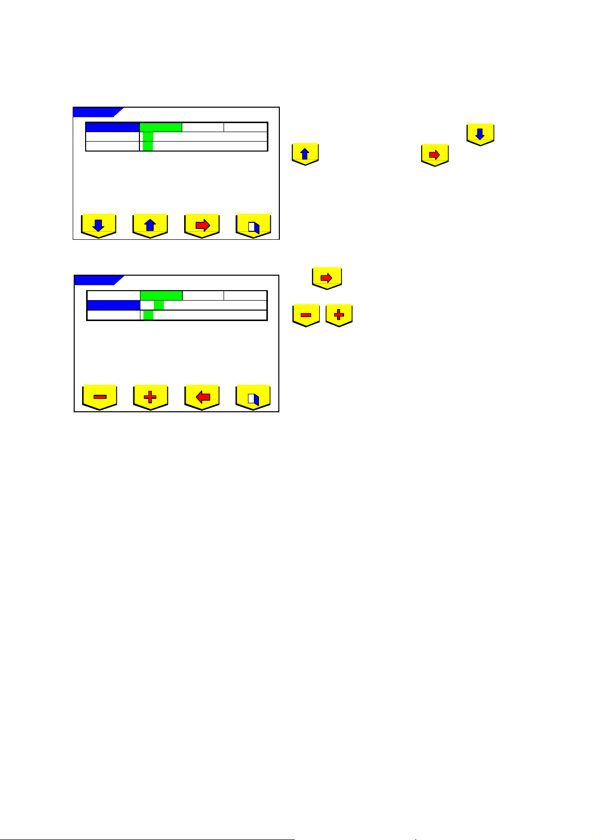
4.2.4. Date/Time Screen
Screen (1)
Date
Time
10
: 08 : 28
Screen (2): Memory/Add switch is pressed
Date/Time
Date Form
Date
Time
20
02 /01 /18
10
:08 : 28
This is the screen to set date and time shown on the
printout.
Select the item you wish to change using and
, and set the detail with .
Date Form: Y/M/D: year, month, date
D/M/Y: date, month, year
M/D/Y: year, date, month
Date: change of the date
Move the cursor to the item you wish to change
with . While Memory/Add switch is pressed,
Screen (2) will be displayed. Make changes using
.
Time: change of the time
Follow the procedure of 'Date' above.
13
RB-473-B02M
Page 15
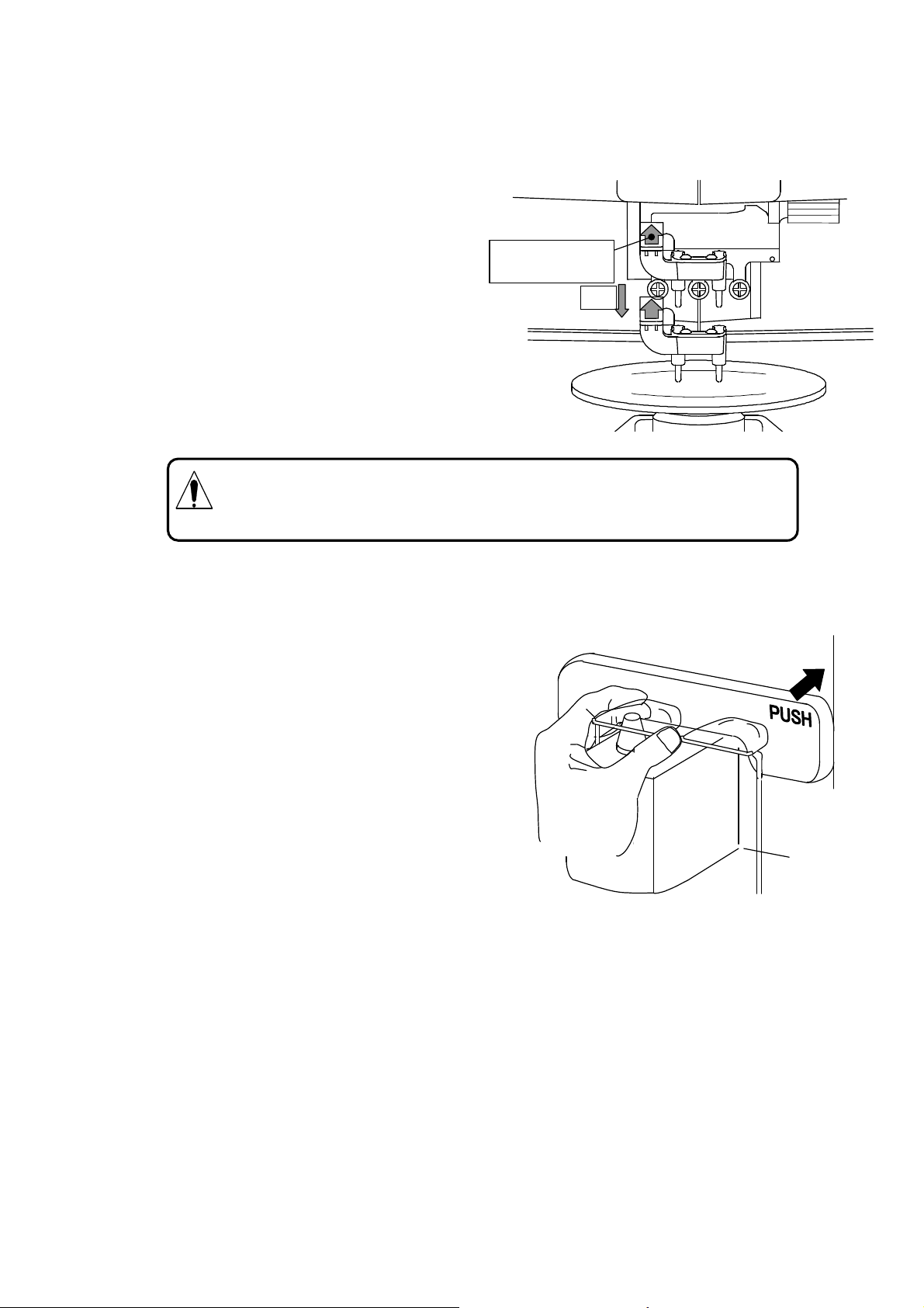
Great care sh all be taken to avoid giving a strong impact to t he lens when lowering
5. How to operate the lensmeter
5.1. Lens holder
(1) Raise the lever to the operational direction until
it is unlocked.
(2) Lower the lens holder slowly and fix the lens.
the lens holder.
Make sure that the lens holder is raised to the top when raising it.
(1) Operational
direction
(2)
5.2. Lens plate
The lens plate is a reference of the astigmatic axis.
(1) Push the PUSH mark on the lens plate to unlock it. The
lens plate will come out.
(To lock the lens plate, push it again.)
(2) The lens plate comes out until it touches the lens when
pushed. Place the frame lens on the lens stand so that the
bottom touches the plate.
14
RB-473-B02M
Page 16
note :
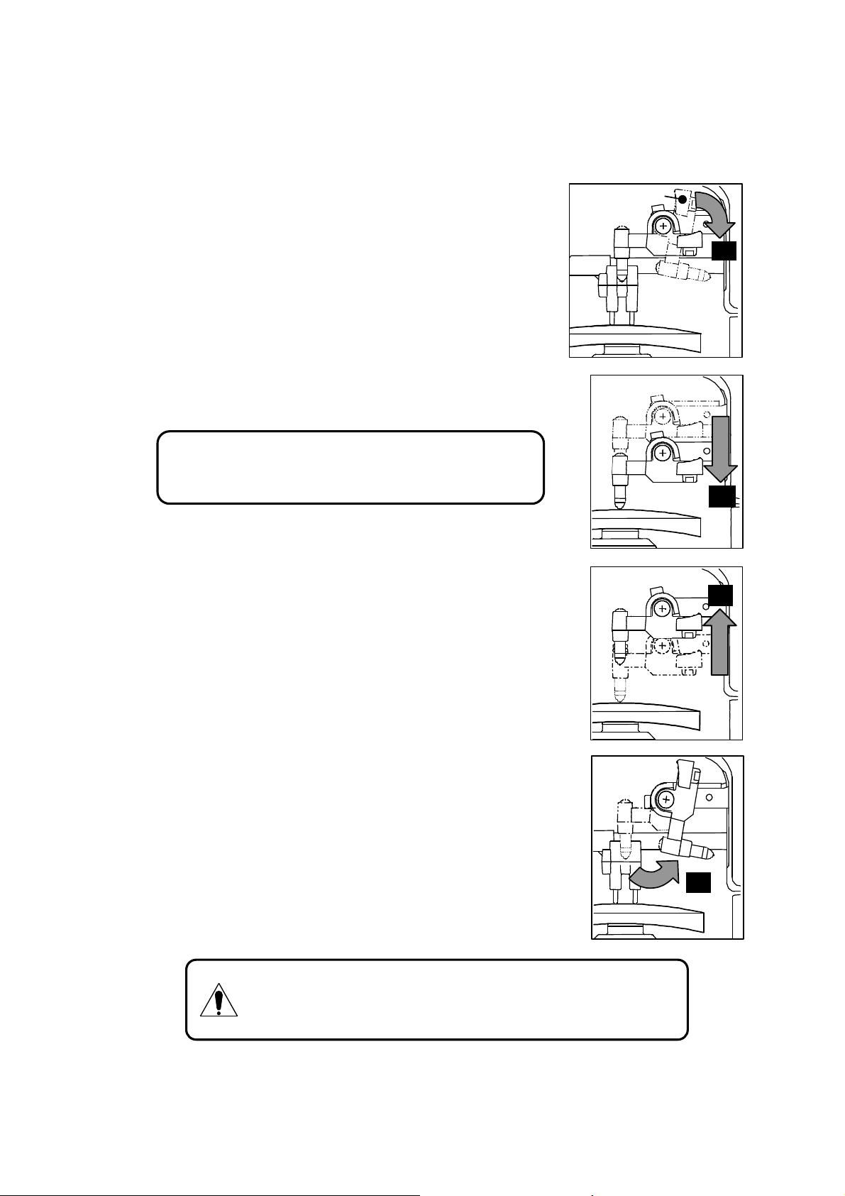
5.3. M arking lever
5.3.1. How to operate
(1) Turn and press the marking lever.
(2) With it turned and press ed, lower the marking lever slowly until the
tips of marking pens touch the lens surface softly.
The marking pen may be damaged early, which
requires replacement.
Do no repeat marking at the same point.
(3) Release the finger slowly after finishing marking on a lens.
(4) Marking lever returns to the initial position.
Observe the following, otherwise you may damage the pen tip.
Do not push the marking pen too hard when marking.
Do not operate the marking lever when no lens is set.
Do not touch the pen tip during cleaning.
marking lever
(1)
(2)
(3)
(4)
15
RB-473-B02M
Page 17
F
lat washer
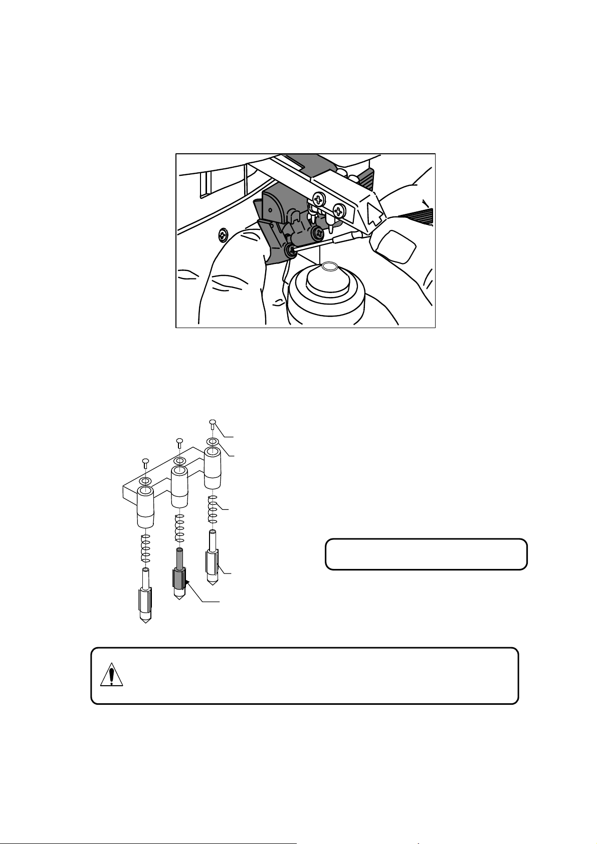
5.3.2. Replacement of marking pen
A marking pen is an article of consumption.
Replace it if an imprint beco mes thin or the pen tip is worn out.
(1) Hold the pen tip of the marking pen (the plastic part) and turn the screw to the left to remove.
(2) Attach a spring to a new marking pen as shown below. Then insert the pen back to the initial
position.
(3) Holding the marking pen, fix it with the screw.
Screw (M24L)
a nominal dia:2
Spring
note : A central marking pen is black
and is shorter than pens on both sides.
Marking pen
Black
Use the marking pen exclusively designed for SLM-5000 only.
Avoid touching the pen tip when replacing. The tip may be damaged.
Do not fasten the screw too tig htly when replacing. You may damage the part.
Avoid losing the screw and spring.
16
RB-473-B02M
Page 18
A : 90
ADD:+3.00
A :
ADD: +3.00
F V
ADD:+2.00
2002 08 25 10: 25
NAME
S : -3. 00
C : -0.50
A : 90
P : 0.00 253 B
NAME
ADD: +2.50
NAME
2002 08 25 10:25
2002 08 25 10:25
S : -0.00
C : -2.75
A :
90S : +2.25
C : -0.00
A :
0
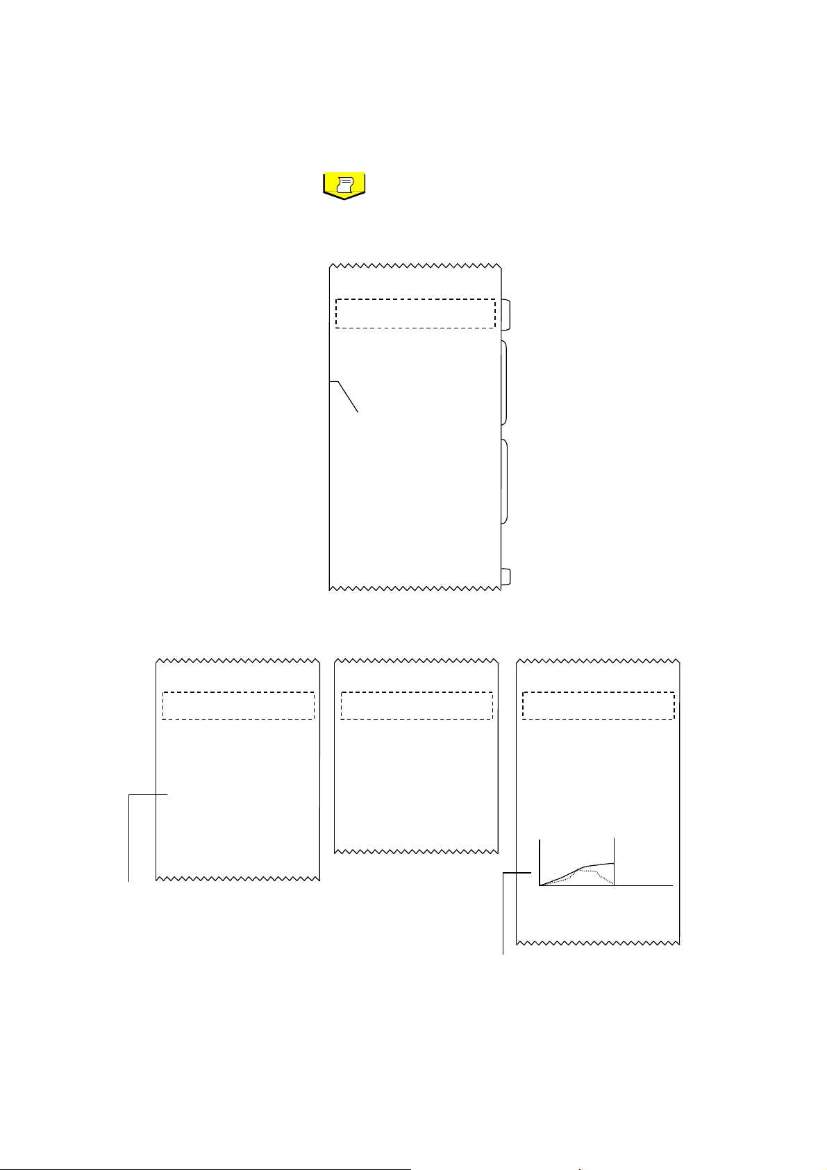
5.4. Printer
5.4.1. How to operate
When measurement is finished, press . The measurement result is printed out.
5.4.2. Type of print out
<<Print out sample when lenses for right and left eyes are measured>>
2002 03 25 10:25
NAME
<R>
S : -0.00
C : -2.75
The unit of the prism value
depends on the setting.
P : O 1.50 U 1.50
<L>
S : -0.00
C : -3.00
-0
Store name, comments, etc
(printed out when registered only)
Lens data for right eye
Lens data for left eye
<<Print out sample when a single focal lens is measured>>
<S>
P: O 0.00 U 3. 25
SHIN-NIPPON SLM-5000
ADD value is printed out when
mutifocal or progressive lens is
measured.
P : O 0.00 D 3.50
SHIN-NIPPON SLM-5000
<S>
SHIN-NIPPON SLM-5000
Line feed
<S>
P : O 1.25 U 5.00
N V
SHIN-NIPPON SLM-5000
17
Optical characteristics graph printed.
(When Graph Print is set for On at the
progressive lens measurement.)
RB-473-B02M
Page 19
since it is the part of the printer unit.
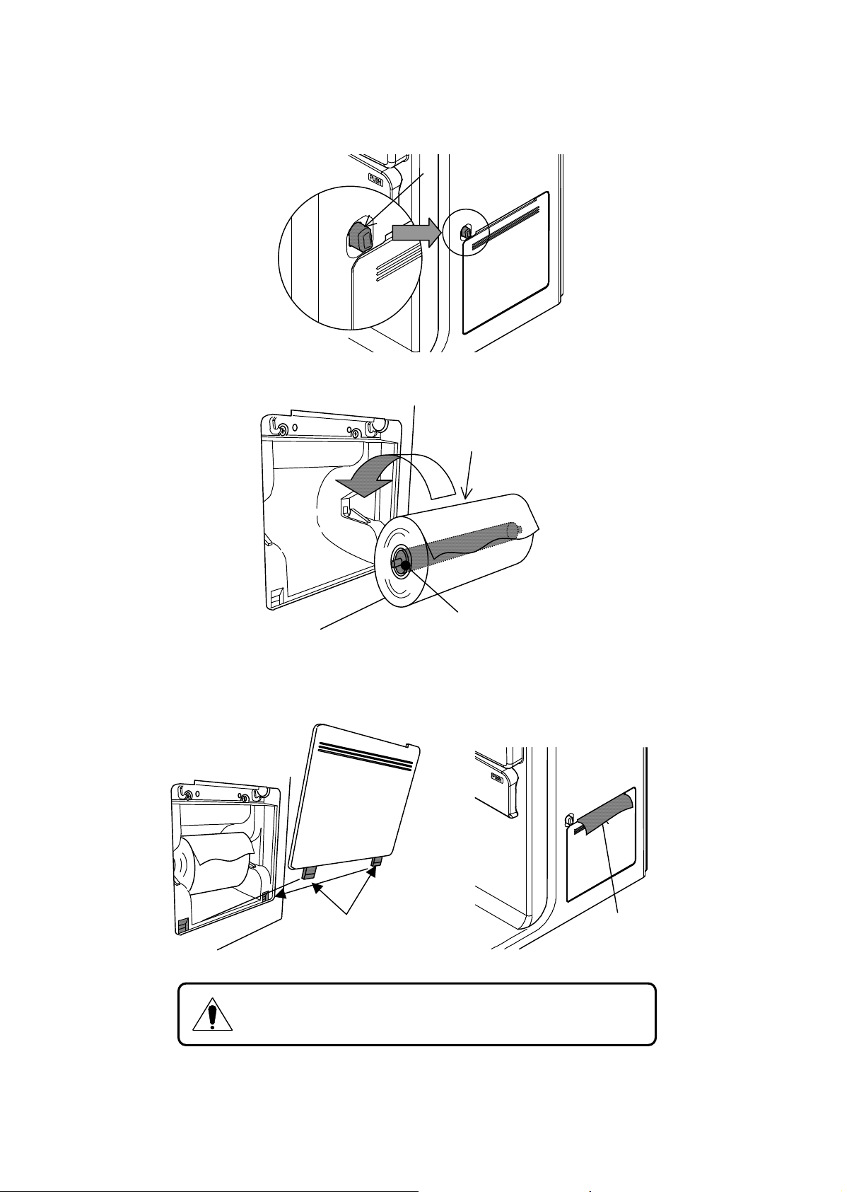
5.4.3. Setting and replacement of printer paper
(1) Push the printer-cover open button to open the cover, and then remove the cover.
Printer-cover open button
(2) Insert the printer shaft into the roll of the paper and set it in the printer unit.
Printer paper
Printer shaft
(3) Hook the tabs of the cover to the tabs of the unit. Take out the end of the paper a little and close the
cover.
Printer cover
Printer paper
Tabs
Use the printer paper exclusive to SLM-5000 only.
Never lose the printer shaft
18
RB-473-B02M
Page 20
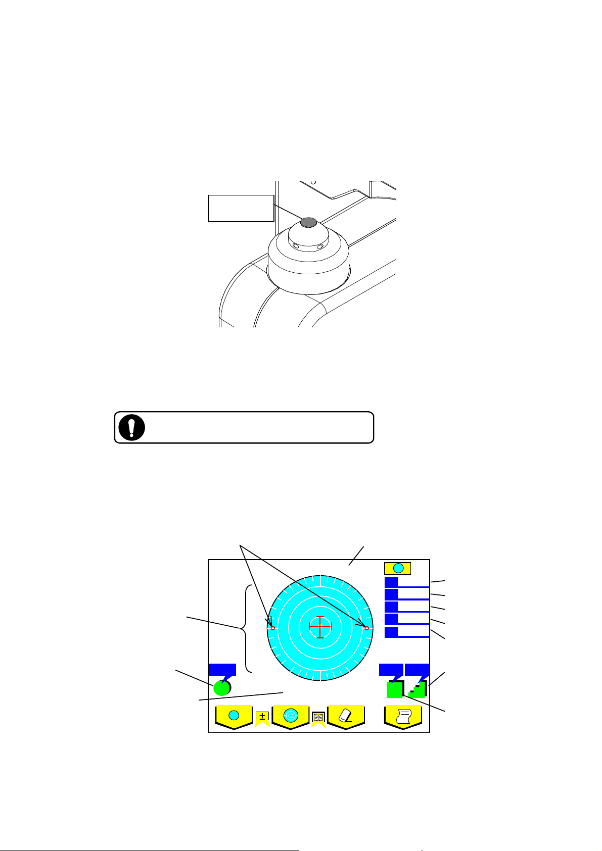
Measuring
Marking OK
0
I 0.00
U 0.00
40
Spherical value
Alignment status/
Error message display area
Axis angle marks
Measurement
Cylindrical value
Axis angle
Prism value: X
Prism value: Y
6. Measurement
6.1. Check before Measurement
Check that the lens stand is set properly.
Check that the lens under the lens stand is clean.
A lens under
the lens stand
A lens stand removed
(If it is dirty, clean it with a soft cloth.)
Plug the power cord to the outlet.
Always make sure that the cable is grounded.
Set the printing paper in a printer.
(See '5.4.3 Setting and replacement of Printer paper.')
Check that no lenses are placed on the lens stand.
Turn the power on. The screen below will appear in a few seconds.
Operation mode display
S
C
A
Px
Py
S
0.00
0.00
Abbe number
StepAbbe
Cyl
±
25
.
S
19
Measurement
increment
Cylindrical sign
RB-473-B02M
Page 21
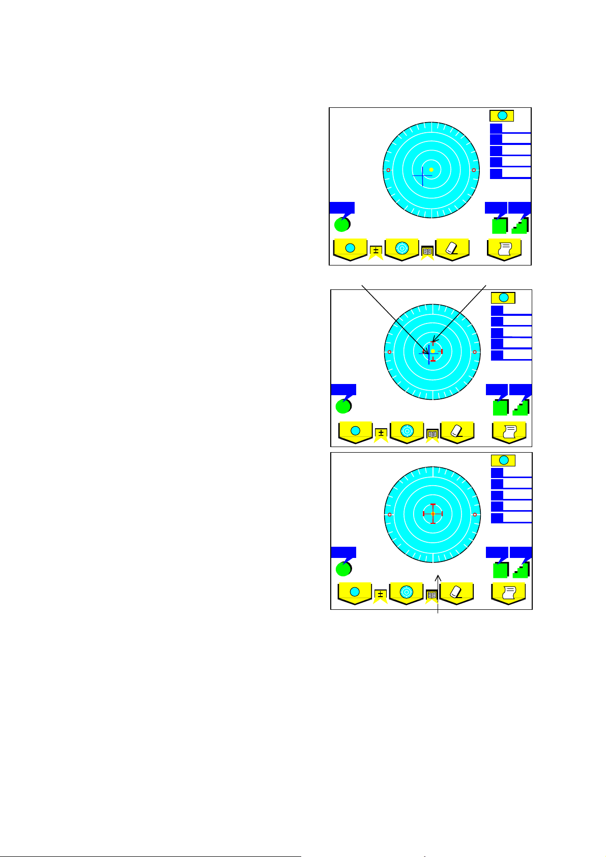
Measuring
-2.00
0
D 0.50
40
S
Alignment mark
Optical center of the lens
Measuring
Alignment OK
0
O 0.25
40
S
Measuring
Marking OK
0.000O 0.00
40
S
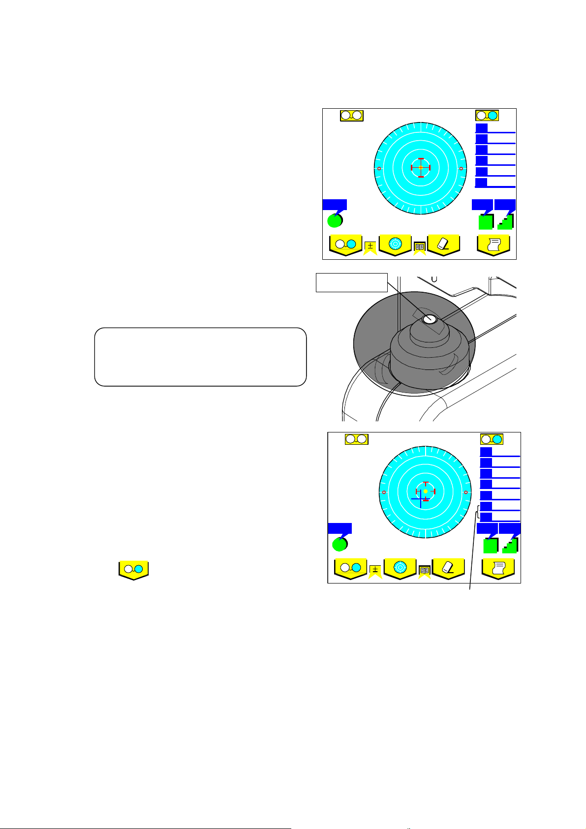
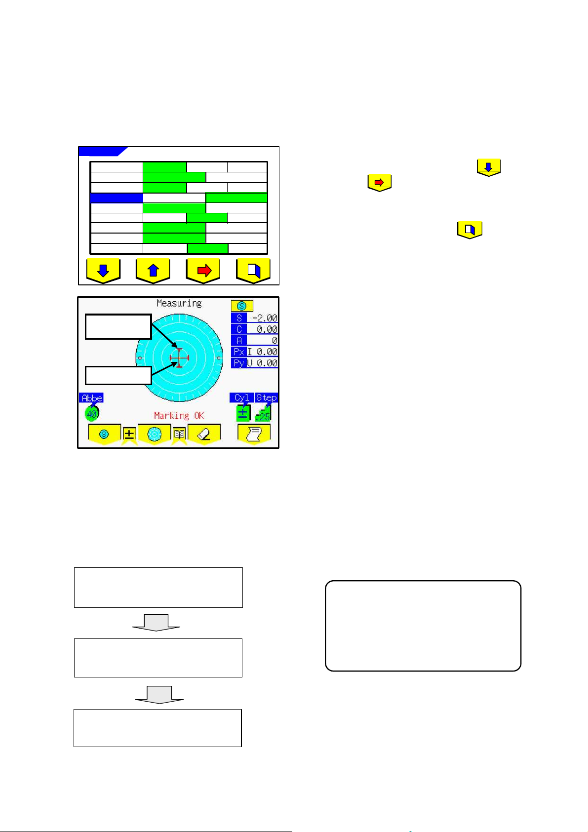
6.2. Single Lens
(1) Place a lens on a lens stand. Lower the lens holder
softly on the lens.
The screen as shown on the right will appear.
(2) Move the lens and bring the cross cursor to the
alignment mark. The message "Alignment OK" will
appear on the screen when alignment completes.
The alignment mark represents the optical center of
the lensmeter and the cross cursor that of the lens.
(3) Move the lens until the cross cursor and the
alignment matches. W hen they match, the message
"Marking OK" will appear to indicate that marking
is ready to be carried out.
S
S
C
A
O 0.75
Px
Py
Cyl Ste pAbbe
±
S
S
C
A
Px
D 0.25
Py
Cyl StepAbbe
±
S
S
C
A
Px
D 0.00
Py
Cyl StepAbbe
±
Message to tell you are ready to mark.
0.00
25.
-2.00
0.00
25.
-2.00
25.
20
RB-473-B02M
Page 22
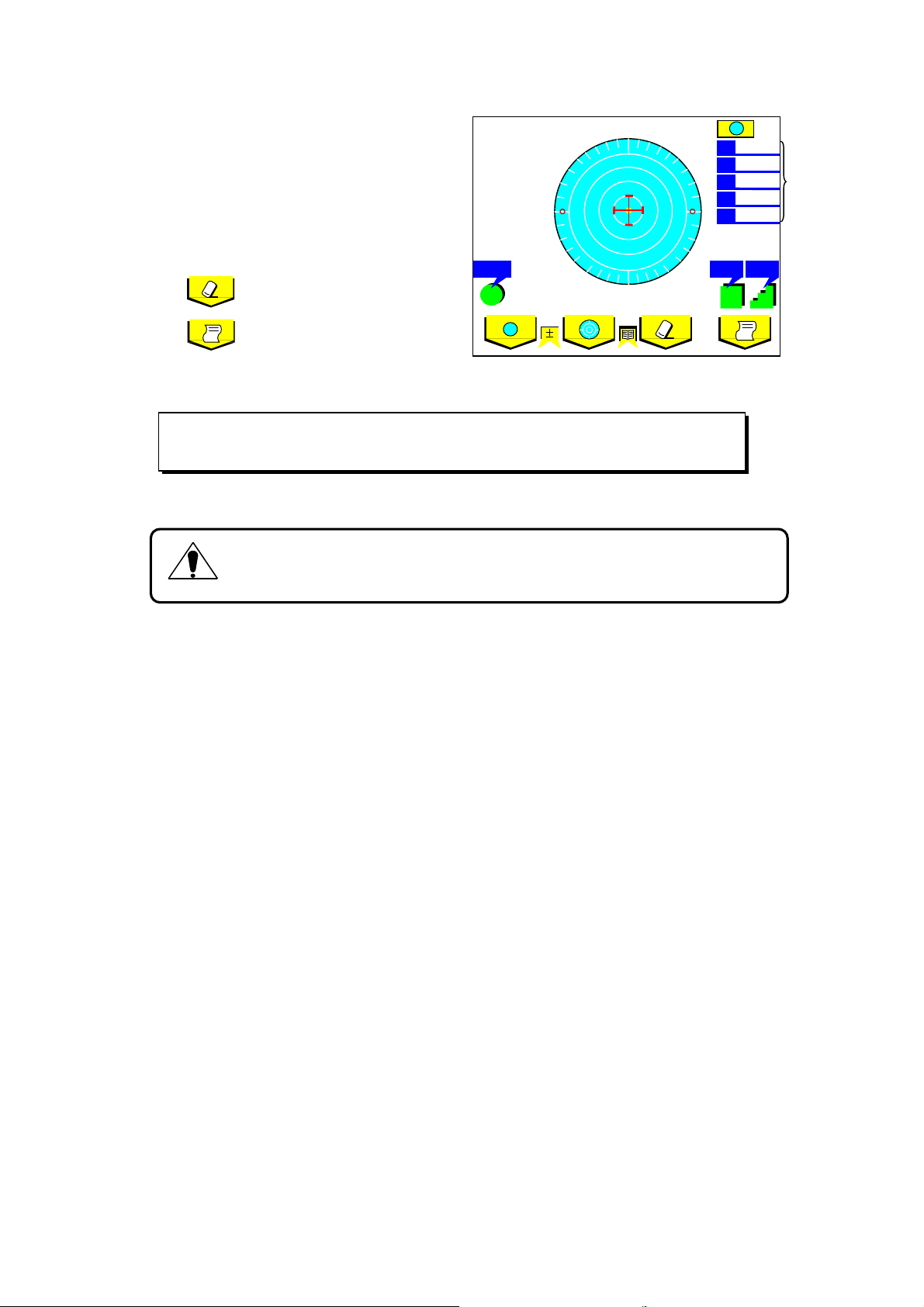
Measuring
Marking OK
4 0±2 5
red
S
(4) Press Memory/Add switch to store
the measurement values of S, C, A
and prism in memory.
The measurement values will be shown
in red at this time. T hen, the values will be fixed.
To erase the data in the memory,
press .
Press to print out the values.
※When setting “Auto Memo ry” “ON” on the set up screen and the messege
“Marking OK” appears, the data will be saved in memory automatically.
Great care should be tak en not to give strong impact to the lens when lowering
the lens holder.
Confirm that the lens holder is locked at the top when pushing it up.
S
C
A
Px
Py
Cyl StepAbbe
S
-2.00
0.00
0
O 0.00
D 0.00
.
21
RB-473-B02M
Page 23
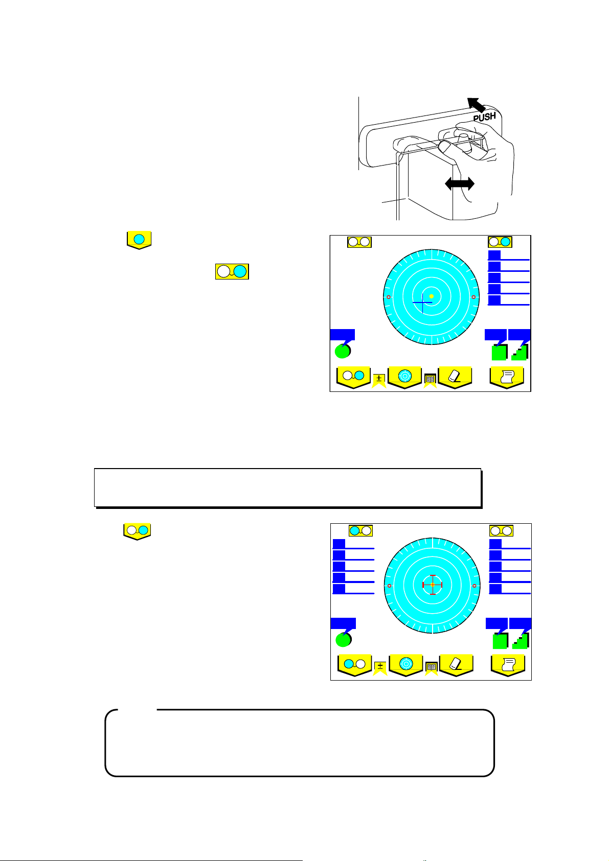
After the data for both right and left lenses are stored in the memory, press CLEAR
S
R
Measuring
C A Px
2.00
0.00
D 0.50
40
± 25 .
R
RL
Measuring
Marking OK
S C A Px
2.00
0.000I 0.00
U 0.00
40
± 25 .
C A Px
L
6.3. Frame Lens
(1) Push "PUSH" mark of a lens plate. The lens plate
will come to the front.
Place a lens on a lens stand so that the bottom of the
frame touches the lens plate.
(2) Press of the operation switches to specify
the lens as either right or left (in this case, right).
Press the switch to display on the upper
R
right of the screen.
(3) Align the lens, following the same procedure as a
single lens measurement.
(4) When the measurement completes, press Memory/Add switch to store the measurement values. When
it is pressed, values of S, C, A and prism will be stored in memory. The values stored in memory are
shown in red.
After stored in the memory, the values displayed on the screen will be fixed.
※When setting “Auto Memory” “ON” on the set up screen and the messege
“Marking OK” appears, the data will be saved in memory automatically.
(5) Press to switch to the lens for a left eye. At
this time, the measurement result for the right lens
is fixed on the screen.
NOTE
Abbe
Py
Abbe
-
S
0
O 0.75
Py
CylSte p
L
-
R
-2.25
S
0.00
I 0.00
U 0.00
Py
CylStep
0
You can start measurement from either right or left lens.
switch so that either data that is selected will be cleared.
22
RB-473-B02M
Page 24
Measuring
Marking OK
40 ± 25 .
C A Px Py
0
L R
Measuring
40
± 25 .
C ylSte pAbbe
C A Px Py
Ad1
Ad2
0
1.50
R
6.4. M ultifocal Lens
(1) Place a lens on a lens stand and lower the lens
holder gently.
(2) Measure the far point and press Memory/Add
switch. When Memory/Add switch is pressed, the
values of S, C, A and prism are stored in memory.
The values stored are fixed and will be shown in
red on the screen.
Press it again, then, the value of Ad1 is also shown.
(3) Measure the near point. Move the lens so that the
near point comes to the center of the lens stand.
NOTE: "Alignment OK" and "Marking OK"
are not necessarily displayed for the
near point measurement.
(4) Press Memory/Add switch to store the ADD value
of the near point in memory.
After the measurement values are stored, ADD
values will become red.
For a trifocal lens, Press Memory/Add switch again
to display Ad2 on the screen. Bring the second near
point into the center of the lens stand again. Then,
repeat the step (3) and (4).
(5) Press to change to the right lens
R
measurement. The measurement result of the left
lens is left displayed on the screen at this time.
Abb e
Near point area
L
Marking OK
ADD value
R
-2.00
S
0.00
I 0.00
U 0.00
0.00
Ad1
CylSt ep
R
-2.00
S
0.00
I 0.50
U 0.75
0.75
23
RB-473-B02M
Page 25
When ADD value is small (under 1D), automatic judgment may fail. When the progressive
judgment may also fail. In such a
When ADD value is small (under 1D), the lens in the frames is small, or the lens has
automatically detected. In
NOTE
Pr ogressive
C A P
B
217
40
± 25 .
Off
On
On
Normal
On
Step
Auto Memory
F/N.A T
N.AT Manual
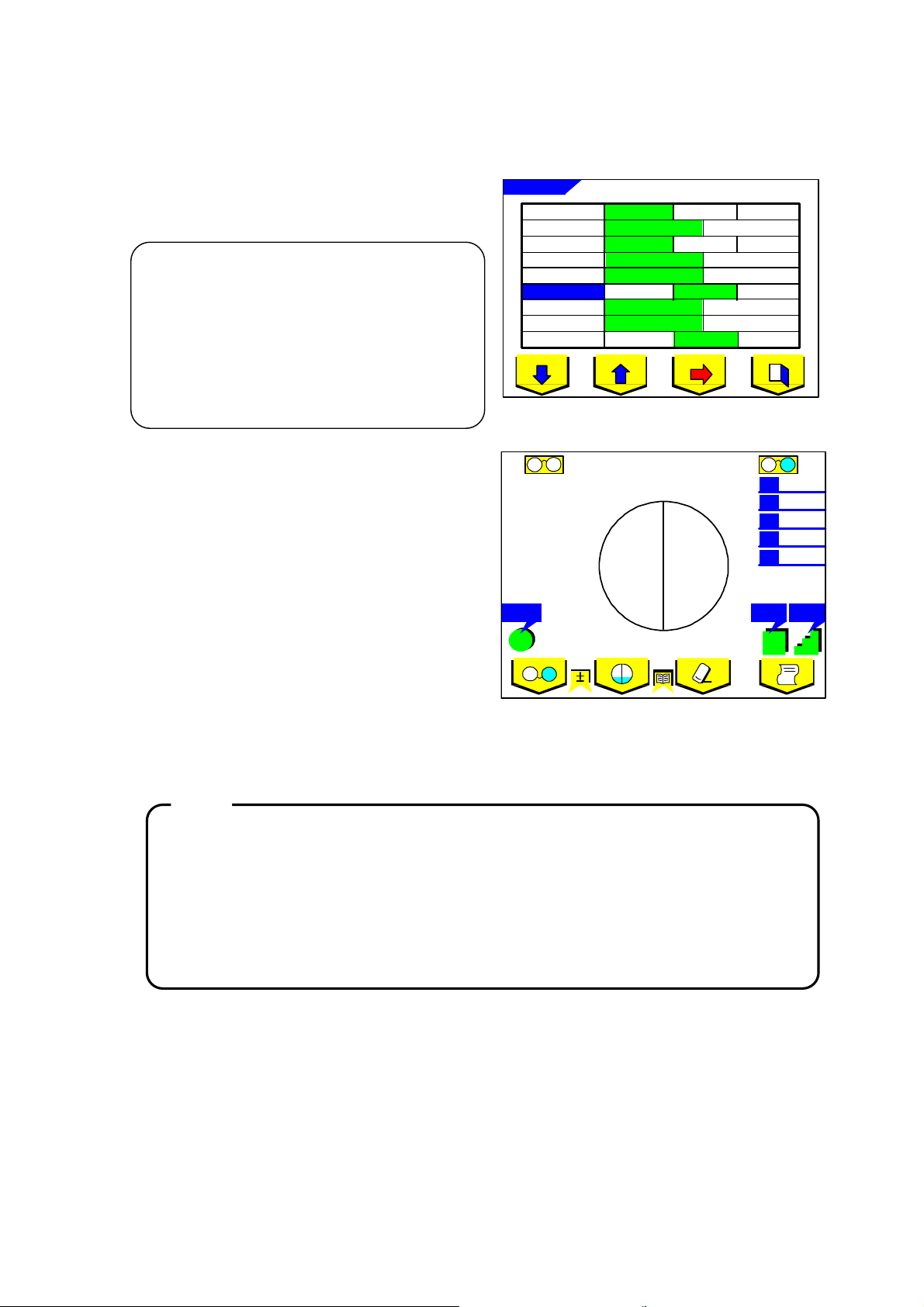
6.5. Progressive Lens
(1) Set up the items for progressive lens measurement
in the Menu screen. Press MENU switch and set
Prog Auto and ADD Measure.
Prog Auto:
Off: No automatic judgment for a progressive lens
On: automatic judgment for a progressive lens
ADD Measure:
F/N.AT: automatic measurement of a far and a
N.AT : automatic meas urement of a near point
Manual: manual measurement of a far and a
near point
near point
Set up
Lens Swit ch
Lens
Prog Au to
ADD Measure
Prog. Graph
Graph Print
Prism
0.25
S/R/L
Off
0 .12
H Cont S Cont
Off
Off
Off
X-Y
L
(2) Press the measurement selection switch (see 4.1
Switch function) to display the progressive lens
measurement screen.
When Prog Auto is On, you can automatically
Abbe
check whether the lens is a progressive lens or not.
Set the lens so that the possible progressive area is
placed on the lens stand. Then, the automatic
R
judgment starts.
When the lens is identified as a progressive lens, the progressive lens measurement screen appears.
When the lens is not a progressive lens, the progressive lens measurement screen does not appear.
area is not properly placed on the lens stand, automatic
case, try to move the lens slowly back and forth or to the right or left.
significant flaws or stains, the far and near points may not be
such a case, try to measure manually.
(See the last part of this section for manual operation of a progressive lens measurement.)
0.01
R/L
On
P-B
S
CylSte p
1/2
R
+2.75
+1.25
10
1.00
24
RB-473-B02M
Page 26
Progressive
C A P
B
+2.75
.00 10
1.00
217
40
R
Progressive
40
1.00
S C A Px Py
AD2
Progressive
+2.75
.00 10
1.00
217
0.0040
R
C A P B
Progressive
C A P
B
+2.75
.00 10
1.00
217
40
R
When selecting “F/N.AT” of “ADD Measure” on
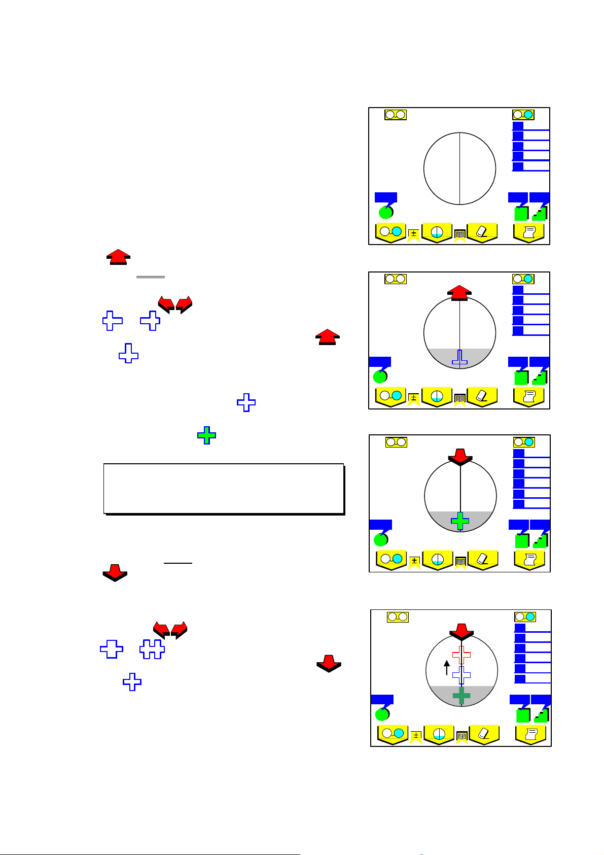
(3) How to measure the progressive lens (when ADD Measure is set for N.AT)
1) Detection of the progressive area
First move the lens slowly to the right and left, and back
(1)
L
and forth to find the progressive area. When the progressive
area is detected, the screen (2) appears.
When the progressive area can not be detected because
the ADD value is small, press Memory/Add switch. You
can call up the screen (2).
Abbe
2) Far point measurement
When you move the lens toward the instrument according to
, the shape of the alignment cursor changes. Move
the lens slowly
to the far point.
(2)
L
When the progressive area is off the lens stand, the arrow
changes to and the cursor changes to
or . In such a case, move the lens to the right
and left until the arrow and cursor change back to
and respectively. Then, move the lens toward the
Abbe
instrument.
Once the far point is detected, The alignment cursor
changes to a symmetrical cross , as shown in the
screen (3). When the Memory/Add switch is pressed, the
(3)
cursor becomes green . Then, the measurement value
L
of the far point is stored in memory.
※
the set up screen, a measurement value of a
far point is saved automatically too.
Abbe
3) Near point measurement
Move the lens slowly
toward you according to the arrow
as shown in the screen (4) so that the alignment
cursor moves toward the near point.
When the progressive area is off the lens stand, the arrow
(4)
L
changes to and the cursor changes to
or . In such a case, move the lens to the right
and left until the arrow and cursor change back to
and respectively. Then, move the lens toward you.
Abbe
When the near point approaches, the alignment cursor
changes from blue to red. Carry out alignment carefully.
When the near point is attained, a bleep sounds and the
R
cursor becomes green. At the same time, the Add value is
automatically stored in memory.
Cyl
Cyl
Ad1
Cyl
Ad1
Cyl
S
S
S
+1
±
+1
±
±
±
R
Step
25 .
R
Step
25 .
R
+1
Step
25 .
R
2.75
-1.00
10
1.00
217
Step
25 .
25
RB-473-B02M
Page 27
approx. 10 mm
Near the center of the lens
R
Progressive
40
2.75+1.00 10
1.50
217
1.00
1.00
R
S C A Px Py
Ad2
Progressive
40
± 25
S C A Px Py
Ad2
C A Px Py
Ad2
(5)
Pressing Memory/Add switch after the measurement
allows you to store the Add value (Ad2) at any given
position aside from the Add value already stored in
L
R
+
memory.
After completion of the measurement, set the lens for the left
eye and press . The progressive judgment screen
appears again.
Abbe
Ad1
Cyl
±
Measure the lens following the same procedure for the right
lens.
You can start measurement from either right or left lens.
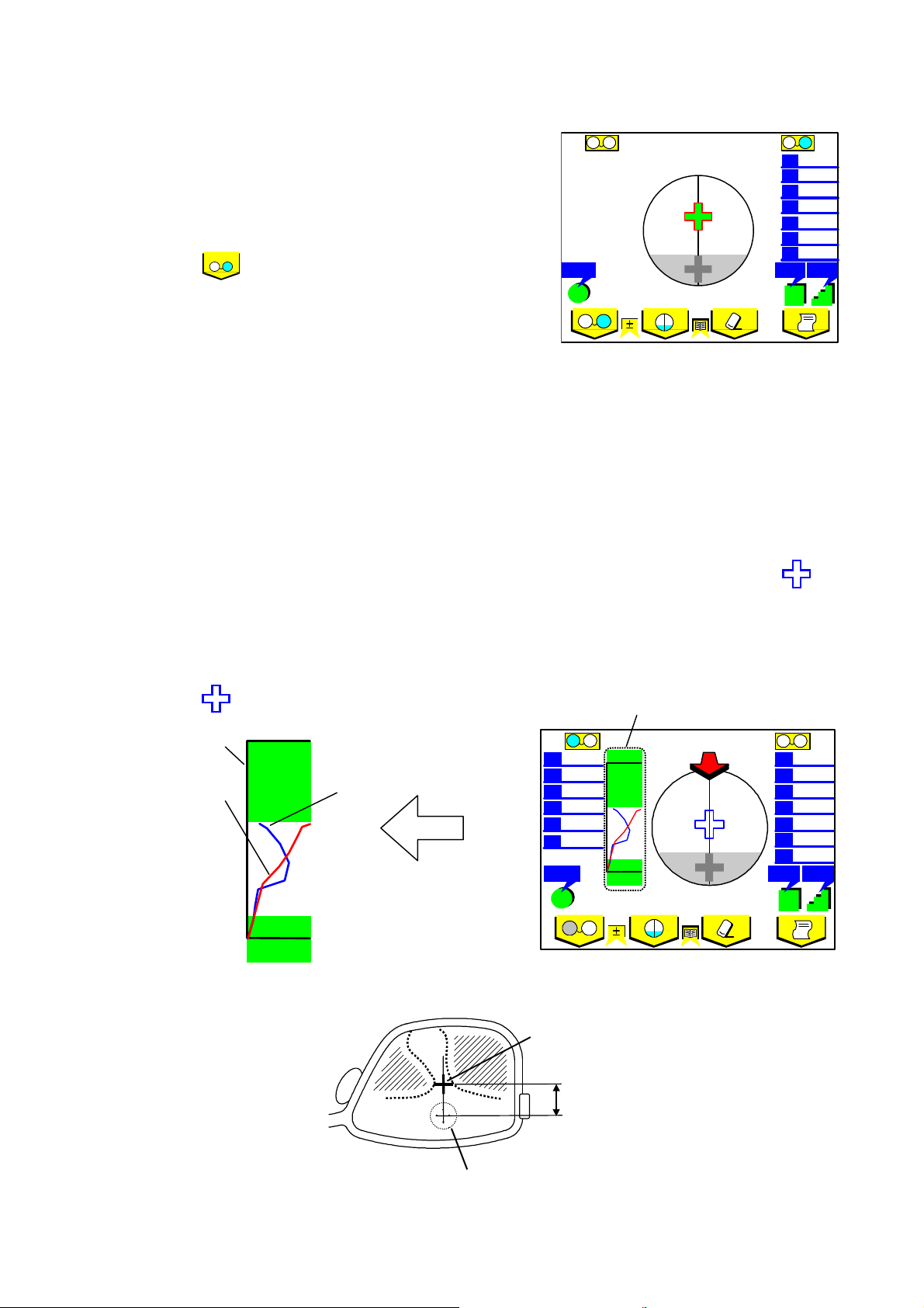
Manual Operation and Graphical Representation of ADD value and Assessment
When you set "Prog. Graph" for ON in the Set up screen, a graph for progressive lens is displayed on the
measurement screen.
Normally the near and far points are automatically detec ted. However, some lenses may be difficult to do
so. In such a case, measure manually based on the graphs of Add value and assessment.
To measure the far point manually, carry out alignment a ccording to the shape of the alignment cursor
as you do for auto measurement.
For near point measurement, press Memory/Add switch where the Add value becomes the highest while the
alignment cursor stays in the progressive area.
When the near point is achieved, the assessment graph touches the Y coordinate. Pay attention to the shape
of the cursor and the graph position when you do alignment.
Y coordinate
Add value
graph
N V
Assessment graph
S
Ad1
Abbe
L
+2.75
+1.25
10
1.00
217
1.00
N V
F V
Graph
R
+2.75
+1.25
Ad1
CylStep
L
F V
<Frame Lens (Reference)>
Far point area
Step
25 .
10
1.00
217
1.00
3.00
.
26
RB-473-B02M
Page 28
mark
Off
On
On
Normal
On
Step
F/N.A T
N.AT Manual
6.6. Auto memory function
SLM-5000 has a function to automatically store the measurement values in memory when alignment
reaches the OK range during measurement of a single focal lens, a multifocal lens and a contact lens.
【How to operate】
Set up
Move the cursor to Auto Memory with and
Lens Swit ch
Lens
Auto Memory
Prog Au to
ADD Measure
Prog. Graph
Graph Print
Prism
0.25
S/R/L
Off
0.12
H Cont S Cont
Off
Off
Off
X-Y
R/L
On
0.01
P-B
1/2
select ON with .
When the setting is completed, press to return
to the measurement screen.
Alignment
The measurement value is stored automatically in
memory when the alignment mark and the cross
cursor overlap as shown on the left.
Cross cursor
6.7. Power saving function
Power saving function is activated when no switches are operated and/or the measurement value is not
updated with the power ON.
(The duration when the power saving function is activated can be selected by "Stand by" in the Set up
screen. )
Measurement mode
Power indicator (PW) lights on
While this function is activated, the power
to the measurement light and the LCD
No operation during a preset time
Power saving
Power indicator (PW) flashing
monitor is turned off.
To return to the measurement state, press
any operation switch.
Return to Measurement mo de
Power indicator (PW) lights on
Press a switch.
27
RB-473-B02M
Page 29
Off
On
On
On
Step
Auto Memory
F/N.A T
N.AT Manual
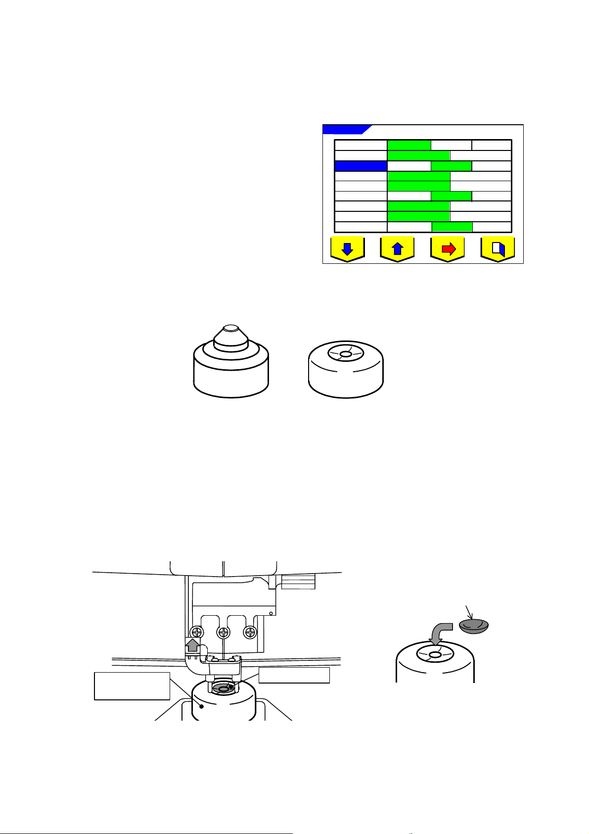
6.8. Contact lens
6.8.1. Preparation
(1) To measure a hard contact lens, select 'H.Cont' in
the Menu screen. For a soft contact lens, select
'S.Cont'.
(2) Change the lens stand to the contact lens stand included in the accessories and measure the contact
lens.
Set up
Lens Swit ch
Lens
Prog Au to
ADD Measure
Prog. Graph
Graph Print
Prism
0.25
S/R/L
Normal H Cont S Cont
Off
Off
Off
Off
0.12
X-Y
0.01
R/L
On
P-B
1/2
Standard nosepiece Contact lens stand
6.8.2. How to measure
(1) Set the contact lens in the contact lens stand as shown below.
(2) Remove the standard lens stand and mount the contact lens stand.
(3) Lower the lens holder and hold the contact lens stand.
(4) Move the contact lens stand vertically and horizontally to bring the lens's center to the center of the
instrument.
Contact lens
Contact lens
Contact lens
stand
Contact lens stand
28
RB-473-B02M
Page 30
Measurin g
C A Px
40 ± 25 .
Measuring
Marking OK
S C A Px
+2.00
0.000I0.00
U0.00
40
± 25 .
S
Measuring
Marking OK
S C A Px
+2.00
+1.00
0
I0.00
U0.00
40
± 25 .
S
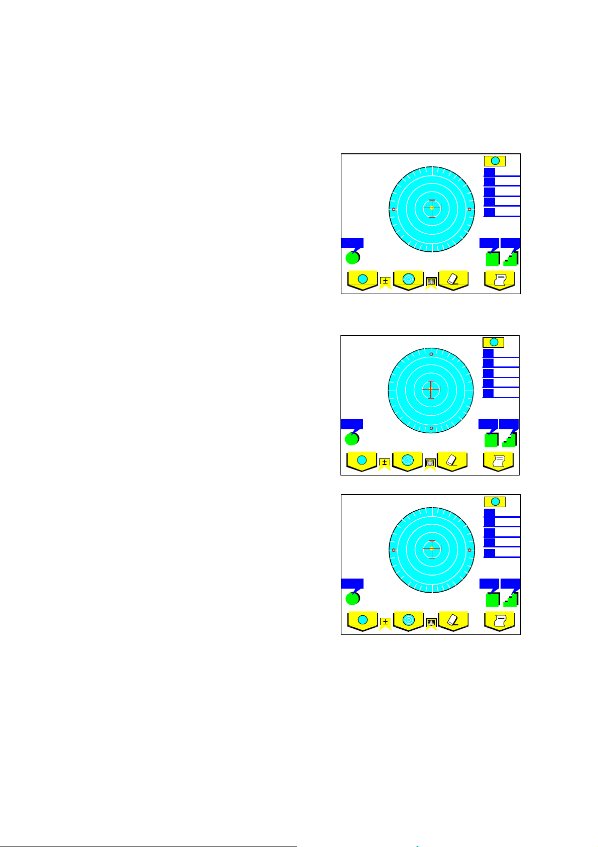
7. Marking
Refer to '5.3 Marking lever' for the lever operation.
7.1. Lens without Astigmatism
(1) Move a lens until a cross cursor matches with the
alignment mark.
When "Marking OK" is displayed, you are ready for
marking.
(2) Lower the marking lever to mark on the lens.
7.2. Lens with Astigmatism
Marking according to the axis in the prescription
(1) Match the target so that the AXIS mark matches the
value in the prescription.
(2) To be more precise, align according to the AXIS value
measured.
Marking on the cylindrical axis
(1) Match the target so that the AXIS marks become
approximately 0°.
(2) To be more precise, align so that the AXIS value
becomes 0°.
Abbe
Abbe
Abbe
S
Py
CylStep
S
+2.00
S
+1.00
90
I0.00
U0. 00
Py
CylSte p
Mar king OK
S
S
Py
Cyl Step
29
RB-473-B02M
Page 31
Meas ur ing
C A
Py
+2.0 0
+1.0 0
0
40
S
Cy lAbbeSt e p
Measurin g
C A P
+2.0 0
+1.0 0
1.50
9040
.
Measur ing
C A P
0
90 40
. S
7.6
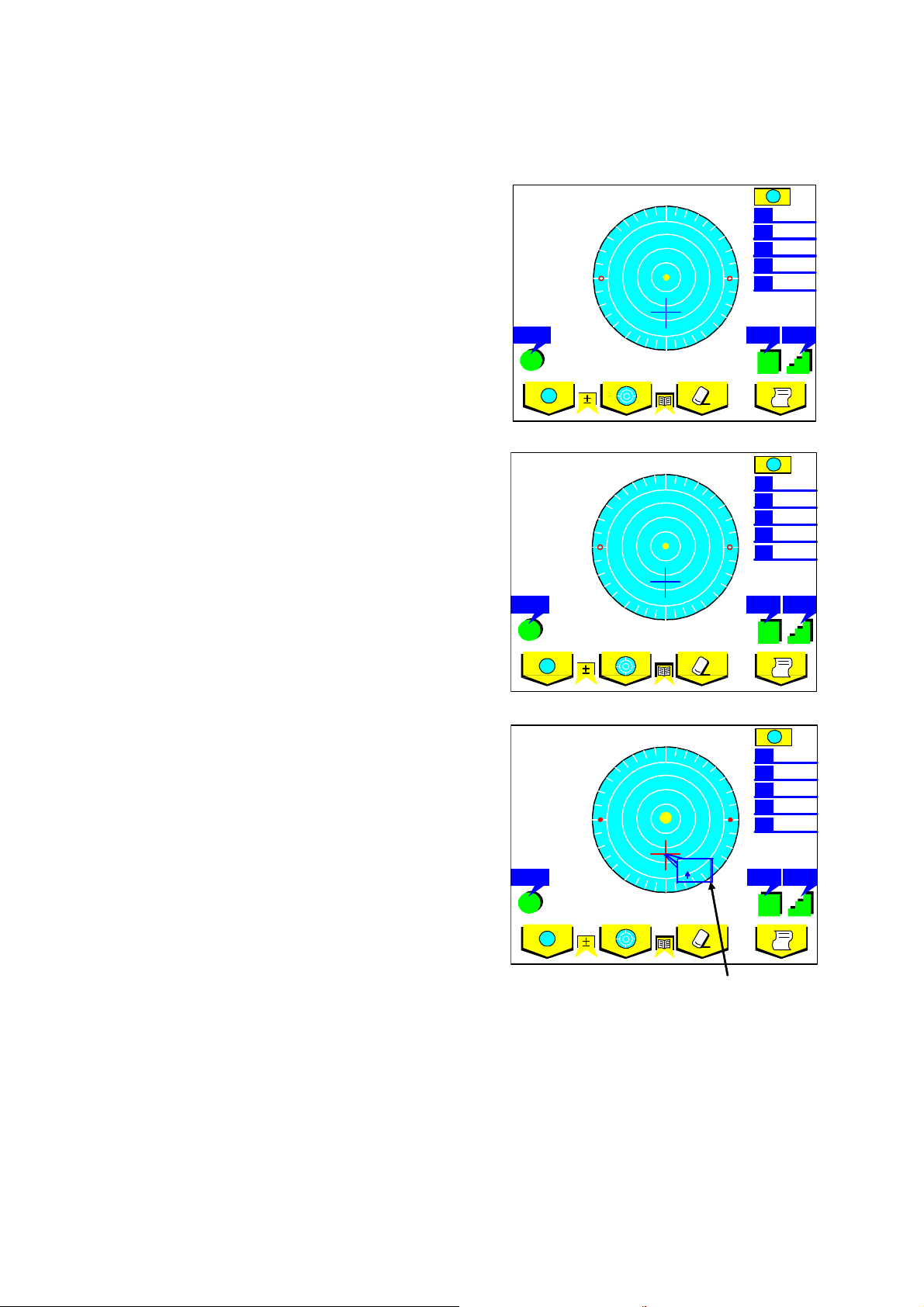
7.3. M arking of prism Lens
Prescription expressed in X-Y
(1) Select "X-Y" from "Prism" in the Menu screen.
(2) Move the lens so that the prism values displayed on
the screen accord with those of the prescription.
Indicated values for prism are as follows.
Px I Base In
Px O Base Out
Py U Base Up
Py D Base Down
Prescription expressed in P-B
(1) Select "P-B" from "Prism" in the Menu screen.
(2) Move the lens so that the prism values displayed on
the screen accord with those of the prescription.
P: Prism value
B: Base direction
Prescription expressed in mm
(1) Select "On" from "Prism(mm)" in the Menu screen.
(2) Move the lens so that the prism values displayed on
the screen accord with those of the prescription.
Arrows ( ) indicates the direction you
should move the lens to make its optical center
reached the measurement center.
Abbe
Abbe
S
0.00
Px
1.50
±
25 .
S
S
S
0
B
Cy l
Step
±
25
S
+2.00
S
+1.00
1.50
B
0.0
S
Cyl
±
Step
25
30
Prism in mm
RB-473-B02M
Page 32
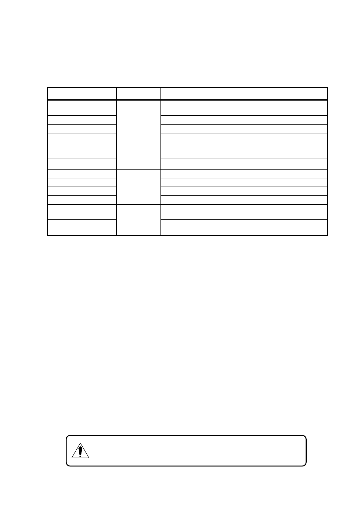
above appear s, or the situation
measures above are taken, cut the power and
8. Error Messages
8.1. Descriptions
Message Status Description
Measure Error
Paper Empty
Printer Cover Open
Printer Heat Over
EEPROM Fault
Sensor Error
Error * * * (100 – 141)
SPH Over
CYL Over
Prism Over
ADD Over
Retry Error
Notarget Error
Abnormality
of the
instrument
Measurement
abnormality
Abnormality
of image
processing
When the power is turned, values are not initialized
(values are not zero (0)).
No papers are set in the printer.
The printer cover is open.
The printer is overheated.
Abnormality of memory
Abnormality of camera sensor
Abnormality of electronic parts (on the 'Control circuit board')
SPH value exceeds the measurement range.
CYL value exceeds the measurement range.
Prism value exceeds the measurement range.
ADD value exceeds the measurement range.
Measurement fails because of dust, flaws, unnecessary light,
and so on.
The measurement light does not enter into the receiving light
sensor.
Display with a three-digit code (number).
8.2. Measures taken for the errors
Measure Error
The message appears if the lens is on the lens stand when the power is turned on, or if the lens under
the lens stand is dirty.
Remove the lens if it is on the lens stand. If the lens under the lens stand is dirty, gently wipe it with a
soft cloth. Then, turn the power back again. (See 6.1 Check before Measurement.)
Paper Empty
The message appears if no papers are set or papers are not set appropriately in the printer.
Set the paper appropriately. (5.4.3. Setting and replacement of printer paper.
Printer Cover Open
The message appears when the printer cover is open. Check the cover and close it if it is open.
SPH/CYL/Prism/ADD Over
The message appears when the lens exceeds the upper limit of the measurement range is measured.
Measure the lens within the measurement range. (See 9. Specifications.)
Retry Error or Notarget Error
The message appears when the direct sunlight or strong glare is on the instrument, or the lens under
the lens stand is extremely dirt y or has some flaws.
When the lens under the lens stand is dirty, gently wipe it with a soft cloth. Then, turn the power back
on.
When error messages other than described
does not improve after the
unplug the power cord, and then contact your distributor.
31
RB-473-B02M
Page 33
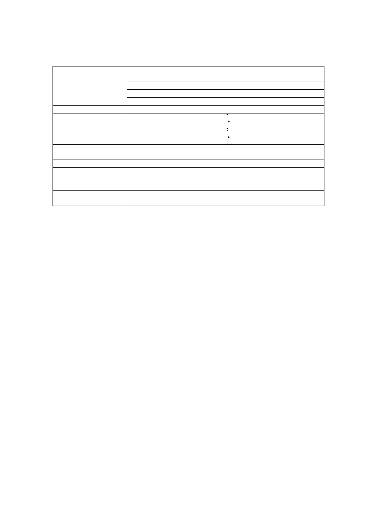
9. Specification
Sphere -25D ~ +25D (0.01/0.12/0.25 step)
Cylinder 0 ~ ±10D (0.01/0.12/0.25 step)
Measurement Range
Measurement wavelength 650nm
Measurable lens
Power supply
Printer Thermal printer (paper width 58mm)
Monitor Color LCD monitor (5.7 inches)
Dimension/weight
Environmental condition
for use
Axis 0 ~ 180° (1°)
Addition 0 ~ +10D (0.01/0.12/0.25 step)
Prism
Unprocessed lens (diameter: 100mm)
Frame lens
Hard contact lens
Soft contact lens
100 ~ 240V
50/60Hz
200(W)x260(D)x443(H)
approx.5.2kg
Temperature: 10°C ~ 40°C
Humidity: 70%HR (no dew condensation allowed)
0 ~ 10
(0.01/0.12/0.25 step)
Single lens, multifocal lens,
progressive lens
A special accessory is required.
10. Applicable Laws and Standards
Law Electromagnetic Compatibility Directive 89/336/EEC
Low Voltage Directive 72/23/EEC
Standard <Safety of a device> EN 61010-1:2001
<Electromagnetic compatibility> EN 61326-1: 1997, Amendment A2: 2001
Class A
32
RB-473-B02M
Page 34

・
Please do not dispose this p r oduct
AJIN
OMOTO TRADING, INC.
Exclusive Distributor
SHIN-NIPPON Medical & Ophthalmic Instruments Dept.
EAST WING 7F, TFT BUILDING, 3-1-22
ARIAKE, KOTO-KU, TOKYO 135-8071, JAPAN
TEL: 813-3528-4416 FAX: 813-3528-4426
http://www.shin-nippon.jp http://www.ajitrade.com
Manufacturer
RyuSyo Industrial Co., Ltd.
Kagawa Factory
958 IKEUCHI, KOUNAN-CHO,
TAKAMATSU, KAGAWA 761-1494, JAPAN
as unsorted municipal waste.
・Please inquire the distributor about
the return and the collection system.
Name:
Address:
RB-473-B02M
 Loading...