

Shindaiwa M231 Owner's/operator's Manual
SHINDAIWA OWNER’S/OPERATOR’S MANUAL
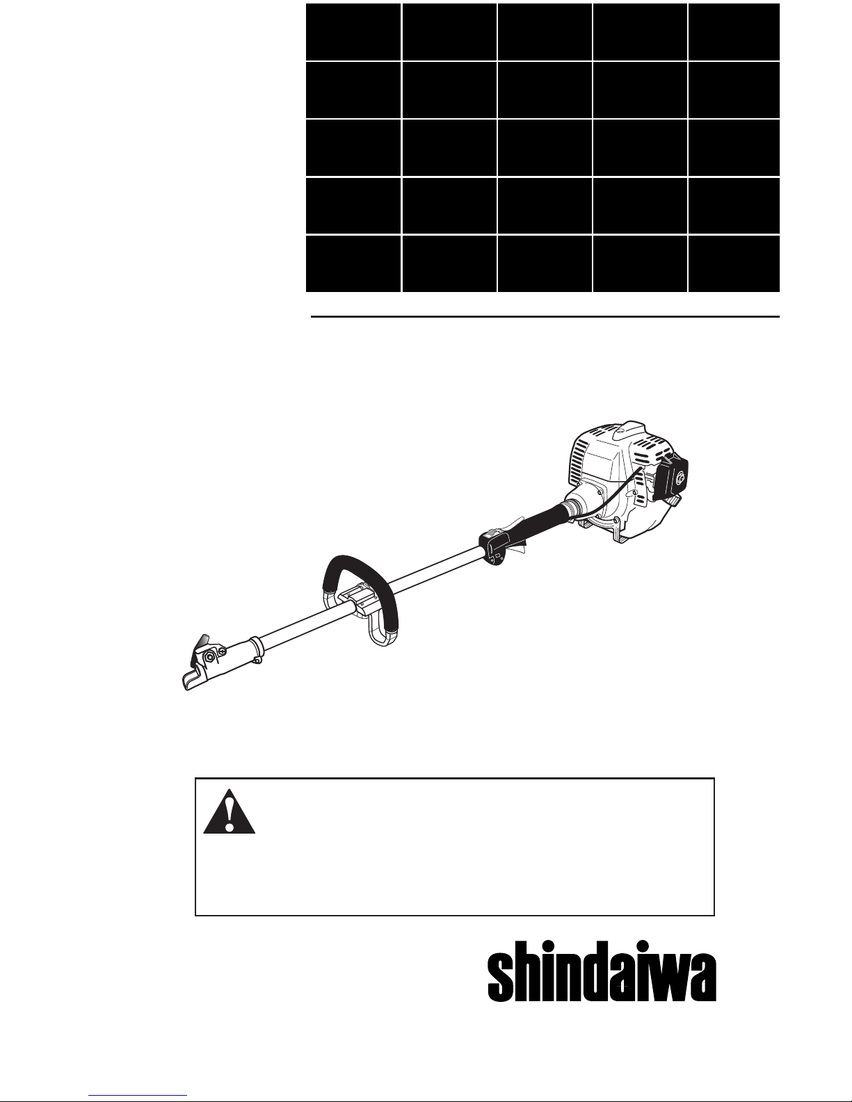
M231 MULTIPURPOSE
TOOL CARRIER
M231
Part Number 65008-94011 Rev. 12/05
®
WARNING!
Minimize the risk of injury to yourself and others! Read this manual
and familiarize yourself with the contents. Always wear eye and
hearing protection when operating this unit.

PAGE
ContentsIntroduction
The Shindaiwa 231-series of handheld power tools has been designed and
built to deliver superior performance and
reliability without compromise to quality,
comfort, safety or durability.
Shindaiwa engines represent the leading edge of high-performance engine
technology, delivering exceptionally
high power with remarkably low displacement and weight. As an owner/operator, you’ll soon discover for yourself
why Shindaiwa is simply in a class by
itself!
Introduction............................................1
Attention Statements.............................2
General Safety Instructions..................3
Safety Labels..........................................4
Operating Precautions..........................5
Product Description..............................6
Specifications.........................................7
Assembly ...............................................8
Installing a Tool Attachment................9
Mixing Engine Fuel.............................10
Starting the Engine.............................11
Stopping the Engine............................13
Adjusting Engine Idle..........................13
Checking Unit Condition....................14
Shoulder Strap......................................14
Maintenance.........................................15
Long Term Storage..............................19
Troubleshooting Guide.......................20
Emission System Warranty.................24
1
IMPORTANT!
The information contained in these
instructions describes units available
at the time of publication.
Shindaiwa Inc. reserves the right
to make changes to products without
prior notice, and without obligation to
make alterations to units previously
manufactured.
WARNING!
The engine exhaust from this
product contains chemicals known
to the State of California to cause
cancer, birth defects or other reproductive harm.
IMPORTANT!
The operational procedures described
in this manual are intended to help you
get the most from your unit as well as
to protect you and others from harm.
These procedures are guidelines for
safe operation under most conditions,
and are not intended to replace any
safety rules and/or laws that may be in
force in your area. If you have questions
regarding your 231-series power tool,
or if you do not understand something
in this manual, your Shindaiwa dealer
will be glad to assist you. You may also
contact Shindaiwa, Inc. at the address
printed on the back of this manual.
SAFETY
2
Throughout this manual are special
“attention statements”.
WARNING!
A statement preceded by the
triangular attention symbol and the
word “WARNING” contains information that should be acted upon
to prevent serious bodily injury.
CAUTION!
A statement preceded by the word
“CAUTION” contains information
that should be acted upon to prevent mechanical damage.
Attention Statements
IMPORTANT!
A statement preceded by the word
“IMPORTANT” is one that possesses
special significance.
NOTE:
A statement preceded by the word
“NOTE” contains information that is
handy to know and may make your job
easier.
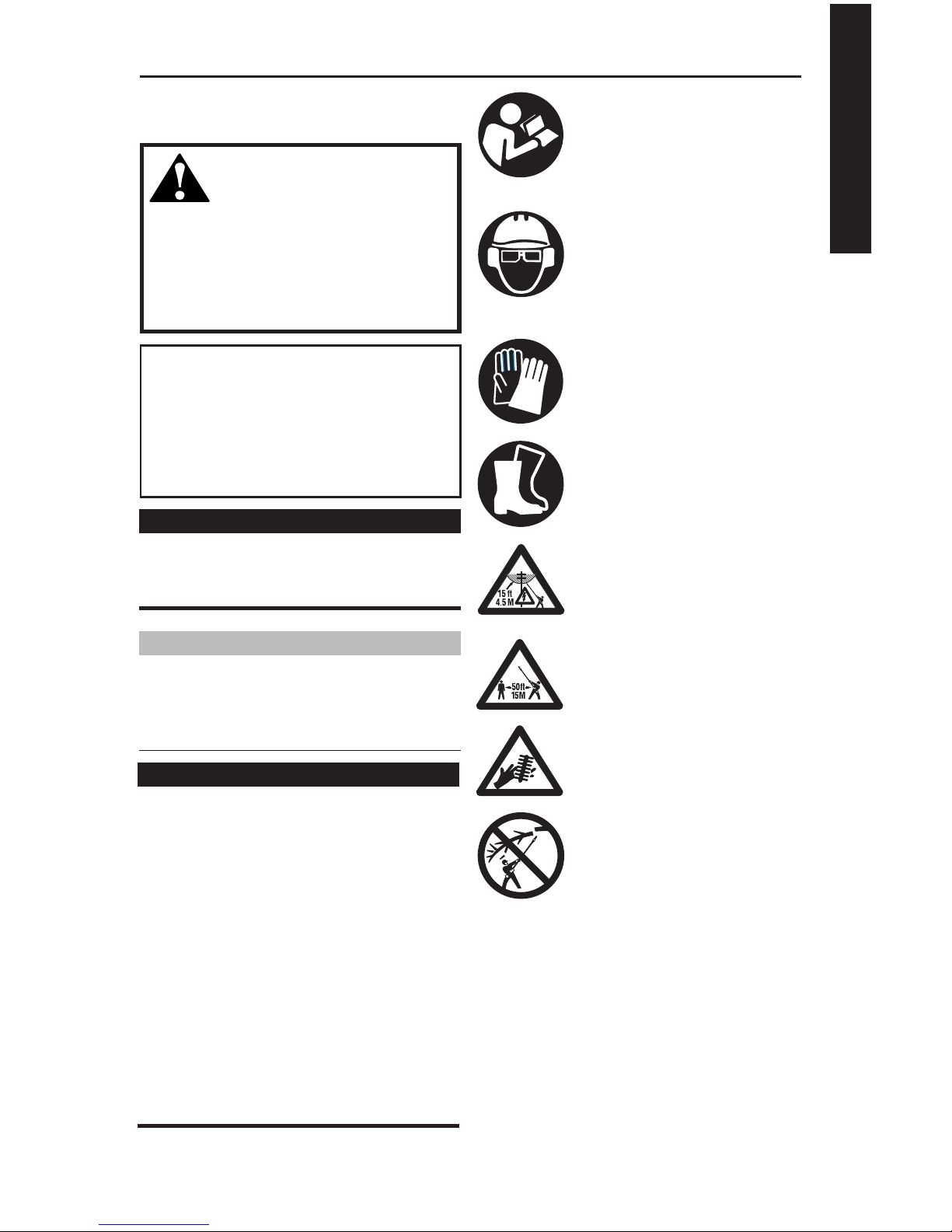
Read and follow this manual, make
sure anyone using the trimmer does
likewise. Failure to do so could result
in serious personal injury or machine
failure. Keep this manual for future
reference.
Always wear a hard hat to reduce the
risk of head injuries during operation
of this machine. In addition, always
wear eye and hearing protection.
Shindaiwa recommends wearing a
face shield as additional face and eye
protection.
Wear heavy duty, non-slip gloves.
Safety tip shoes or boots with non-slip
sole should be worn.
This product conducts electricity.
Keep the product and/or operator
a minimum distance of 15 feet (4.5
meters) away from electrical sources
and power lines.
Keep bystanders at least 50 feet (15
meters) away from the operating trimmer to reduce the risk of being struck
by falling objects or thrown debris.
The blades / cutting attachments are
SHARP! Handle with care.
Be aware of the danger of falling
debris.
SAFETY
3
Work Safely
Attachments for this M231 Multipurpose
Tool Carrier operate at very high speeds
and can do serious damage or injury if
they are misused or abused. Never allow
a person without training or instruction to
operate your unit!
WARNING!
Use Good Judgment
ALWAYS wear eye protection to
shield against thrown objects.
ALWAYS protect yourself from
hazards such as thorny brush
and ying debris by wearing
gloves and close tting cloth-
ing that covers arms and legs.
Never wear shorts. Don’t wear
loose clothing or items such as
jewelry that could get caught
in machinery or underbrush.
Secure long hair so it is above
shoulder level.
NEVER run the engine when
transporting the unit.
NEVER operate the engine indoors! Make sure there is always
good ventilation. Fumes from
engine exhaust can cause serious injury or death.
ALWAYS clear your work area
of trash or hidden debris that
could be thrown back at you or
toward a bystander.
ALWAYS use the proper cutting
tool for the job.
ALWAYS stop the unit immediately if it suddenly begins
to vibrate or shake. Inspect for
broken, missing or improperly
installed parts or attachments.
ALWAYS keep the unit as clean
as practical. Keep it free of loose
vegetation, mud, etc.
ALWAYS hold the unit rmly
with both hands when cutting or
trimming, and maintain control at
all times.
ALWAYS keep the handles
clean.
ALWAYS disconnect the spark
plug wire before performing any
maintenance work.
Stay Alert
You must be physically and mentally fit
to operate this unit safely.
General Safety Instructions
WARNING!
Never make unauthorized
attachment installations.
WARNING!
Never operate power equipment of
any kind if you are tired or if you are
under the inuence of alcohol, drugs,
medication or any other substance that
could affect your ability or judgement.
DO NOT OPERATE THIS UNIT�
IF YOU ARE TIRED, ILL OR�
UNDER THE INFLUENCE OF�
ALCOHOL, DRUGS, OR�
MEDICATION.�
�
WARNING!
Minimize the Risk of Fire
NEVER smoke or light res near
the engine.
ALWAYS stop the engine and allow
it to cool before refueling. Avoid
overlling and wipe off any fuel that
may have spilled.
ALWAYS inspect the unit for fuel
leaks before each use. During each
rell, check that no fuel leaks from
around the fuel cap and/or fuel tank.
If fuel leaks are evident, stop using
the unit immediately. Fuel leaks must
be repaired before using the unit.
ALWAYS move the unit to a place
well away from a fuel storage area
or other readily ammable materials
before starting the engine.
NEVER place ammable material
close to the engine mufer.
NEVER run the engine without the
spark arrester screen in place.
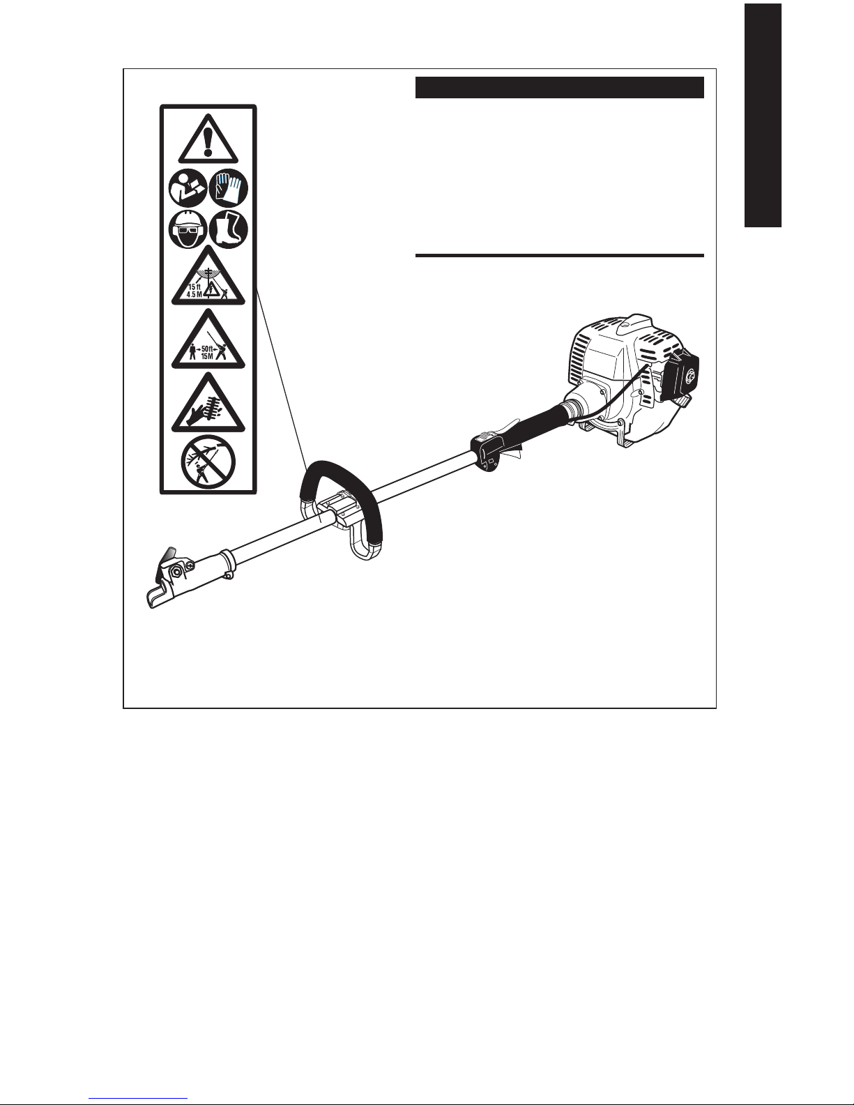
Safety Labels
Figure 1
IMPORTANT!
Safety and Operation Information
Labels: Make sure all information
labels are undamaged and readable.
Immediately replace damaged or missing information labels. New labels are
available from your local authorized
Shindaiwa dealer.
M231
SAFETY
4

CAUTION!
Operating Precautions
Always make sure the cutting
attachment tool is properly
installed and rmly tightened
before operation.
Never use a cracked or warped
cutting attachment: replace
it with a serviceable one and
make sure it ts properly.
Keep the unit away from exces-
sive heat. Engine fuel is very
ammable and re could lead
to serious personal injury or
property damage.
Make sure there are no missing
or loose fasteners, and that the
stop switch and throttle controls
are working properly.
WARNING!
Before starting the engine,
make sure the cutting attachment is not contacting anything.
Always stop the engine imme-
diately and check for damage
if you strike a foreign object or
if the unit becomes tangled.
Do not operate with broken or
damaged equipment.
Never transport the unit or set it
down with the engine running.
An engine that’s running could
be accidently accelerated causing the cutting attachment to
rotate.
Make sure cutter safety guards
are in place when transporting
the unit.
Never extend trimming line beyond
the length specied for your unit.
Always keep the unit as clean
as practical. Keep it free of loose
vegetation, mud, etc.
SAFETY
5
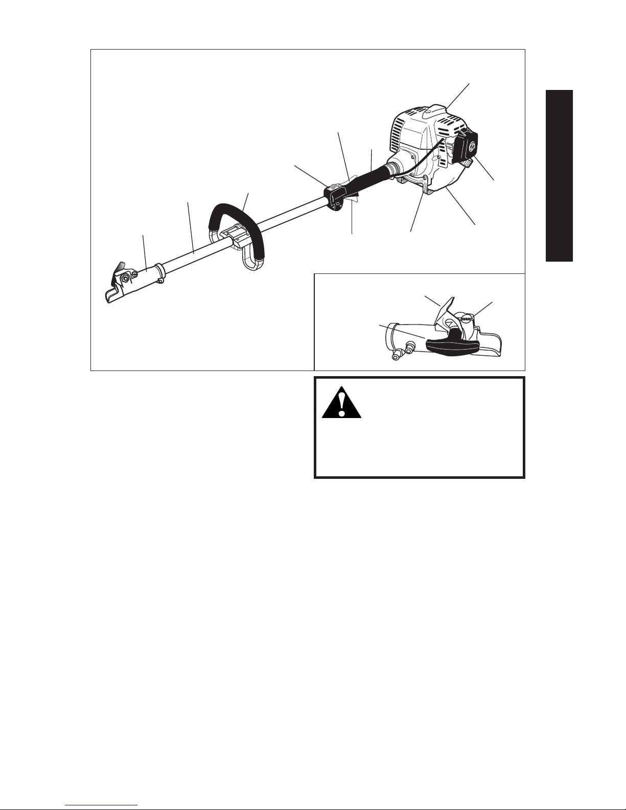
Product Description
M231 Multipurpose
Tool Carrier
Outer Tube
Fuel Tank
Grip
Using the accompanying illustrations
as a guide, familiarize yourself with
your unit and its various components.
Understanding your unit helps ensure
top performance, long service life, and
safer operation. See Figure 2 and 2a.
Handle
Coupler
Throttle
Trigger
Throttle Lockout
Lever
Tank Guard
Figure 2
Ignition
Switch
Air Cleaner
Spark Plug
M23002a
Coupler Screw Knob
Latch
Latch protector
Figure 2a
6
DESCRIPTION
WARNING!
Do not make unauthorized modi-
cations or alterations to any of
these units or their components.

Specications
M231 Multipurpose Tool Carrier dry weight (less attachments) ......4.5 kg/9.8 lb.
Engine model ................................................................................. Shindaiwa S230C
Engine type ........................................................2-cycle,vertical-cylinder, air-cooled
Bore x stroke ...................................................................32 x 28 mm/1.26 x 1.10 in.
Displacement .................................................................................22.5 cc/1.4 cu. in.
Maximum power ............................................... 0.8 kW/1.1 HP@ 7500 rpm (min-1)
Fuel/oil ratio...... ..... 50:1 with ISO-L-EGD or JASO FC class 2-cycle Mixing Oil*
Fuel tank capacity ..............................................................................670 ml/22.7 oz.
Carburetor type ...................................................Walbro WYL-122 diaphragm-type
Muffler ............................................................................................. 2-Stage, Catalyst
Ignition ...................................................One-piece electronic transistor-controlled
Spark plug ............................................................................................Champion CJ8
for EMC compliance use NGK BMR6A
Air cleaner type ............................................ Non-reversible flocked filter element
Starting method ................................................................................................ Recoil
Stopping method ..................................................................................... Slide switch
Transmission type ....................................................... Automatic centrifugal clutch
Optional Assessories ..........................................................................Shoulder strap
EPA Emission Compliance Period* ....................................................... Category A
* The EPA emission compliance referred to on the emission compliance label located on
the engine, indicates the number of operating hours for which the engine has been shown
to meet Federal emission requirements. Category C = 50 hours (Moderate), B = 125 hours
(Intermediate) and A = 300 hours (Extended).
Prior to Assembly
Before assembling, make sure you
have all the components required for a
complete unit:
Engine/Outer tube assembly
Handle
Kit containing handle mounting
bracket and hardware, this owner’s/
operator’s manual and tool kit for
routine maintenance. Tool kits vary
by model and may include a hex
wrench, spark plug/screwdriver
combination wrench, and spanner
wrench.
Specifications are subject to change without notice.
Carefully inspect all components for
damage.
7
DESCRIPTION
meets or exceeds these specifications and is recommended for all Shindaiwa products.
IMPORTANT!
The terms “left”, “left-hand”, and “LH”;
“right”, “right-hand”, and “RH”; “front”
and “rear” refer to directions as viewed
by the operator during normal
operation.
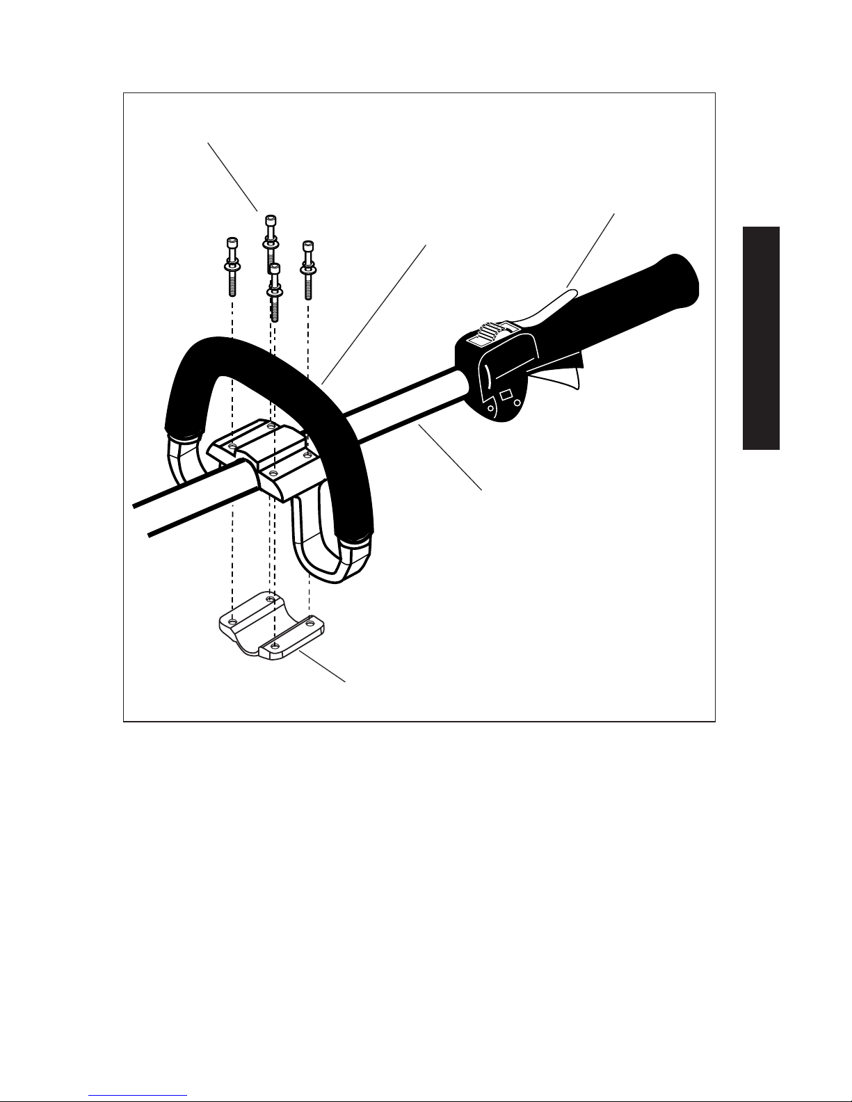
Handle
Connect the Handle to the Outer Tube.
1. Position the handle on the outer
tube as shown. See Figure 3.
2. Install the mounting bracket
with the socket head cap screws.
Tighten the screws finger-tight
ONLY at this time.
3. Locate the handle in the best
position for operator comfort (usually about 10 inches ahead of the
throttle assembly).
4. Secure the handle by alternately
tightening the four socket-head
screws in a diagonal or “criss-cross”
fashion.
Outer Tube
Socket-head Cap-
screws
Handle
Mounting Bracket
Throttle As-
sembly
Figure 3
8
ASSEMBLY
Assembly
 Loading...