

Shindaiwa F226S Operator's Manual

1????
ENGLISH
FRANÇAIS
DEUTSCH
ITALIANO
OPERATOR'S MANUAL
MANUEL D'UTILISATION
BEDIENUNGSANLEITUNG
MANUALE PER L'OPERATORE
F226S
WARNING
READ THE INSTRUCTIONS CAREFULLY AND FOLLOW THE RULES FOR
SAFE OPERATION.
FAILURE TO DO SO COULD RESULT IN SERIOUS INJURY.
AVERTISSEMENT
LIRE ATTENTIVEMENT LES INSTRUCTIONS ET SUIVRE LES RE-GLES DE
SECURITE. LE NON-RESPECT DES REGLES DE SECU-RITE ENTRAINE UN
RISQUE DE BLESSURE GRAVE.
WARNUNG
LESEN SIE DIE BEDIENUNGSANLEITUNG SORGFÄLTIG DURCH, UND BEFOLGEN SIE DIE SICHERHEITSREGELN. ANDERNFALLS BESTEHT DAS
RISIKO SCHWERER VERLETZUNGEN.
AVVERTENZA
LEGGERE E SEGUIRE ATTENTAMENTE LE ISTRUZIONI PER LA-VORARE
IN CONDIZIONI DI MASSIMA SICUREZZA. LA MANCA-TA OSSERVANZA
DELLE ISTRUZIONI POTREBBE PROVOCARE LESIONI GRAVI.

2

1Cover
ENGLISH
(Original instructions)
OPERATOR'S MANUAL
GRASS-TRIMMER
F226S
WARNING
READ THE INSTRUCTIONS CAREFULLY AND FOLLOW THE
RULES FOR SAFE OPERATION.
FAILURE TO DO SO COULD RESULT IN SERIOUS INJURY.

Contents
For safe use of your product...............................................................................................3
Description..........................................................................................................................8
Before you start ..................................................................................................................9
Packing list ....................................................................................................................9
Assembly.......................................................................................................................9
Preparing the fuel ........................................................................................................10
Engine operation...............................................................................................................12
Starting the engine ......................................................................................................12
Stopping the engine............................. ....... ...... ....... ...... ...... ....... ...... ....... ...... ....... .......13
Trimming operation...........................................................................................................14
Basic trimming operation with nylon line cutting head.................................................15
Maintenance and care .............................................................. ....... ...... ....... ...... ....... ...... .17
Servicing guidelines.....................................................................................................17
Maintenance and care .................................................................................................17
Storage........................................................................................................................23
Specifications....................................................................................................................24
Declaration of conformity..................................................................................................25
2

For safe use of your product
For safe use of your product
Important information
WARNING
Please ensure that you read the operator's manual before using your product.
About your operator's manual
This manual contains necessary information about the assembly, operation, and maintenance of your product.
Please read it carefully and absorb its contents.
Always keep your manual in a place where it is readily accessible.
If you have lost your manual or it is damaged and no longer readable, please purchase a new one from your dealer.
The units used in this manual are SI units (International System of Units). Figures in parentheses are reference values, and there may be a slight conversion error in some cases.
Failure to do so could lead to an accident or serious injury.
Intended use of this product
This product is lightweight, high-perform ance, p etrol engi ned unit des igned for weed control and gras s trimmin g in
areas difficult to control by any other means.
Do not use this unit for any purpose other than aforementioned.
The content of this manual may be changed witho ut notice for the pu rpose of upgrades to the product. Some of the
illustrations used may differ from the product itself in order to make the explanations clearer.
Please consult your dealer if anything is unclear or of concern.
Failure to do so could lead to an accident or serious injury.
Do not modify the product
You must not modify the product.
To do so could lead to an accident or serious injury. Any malfunction resulting from a modification to the product will not be
covered by the manufacturer's warranty.
Do not use the product unless it has been checked and maintained
You must not use the product unless it has been checked and maintained . Always ensure that the product is che cked
and maintained on a regular basis.
Failure to do so could lead to an accident or serious injury.
Loaning or assigning your product
When loaning your product to another party, ensure that the person borrowing the product receives the operator's
manual along with it.
If you assign your product to another party , please enclo se the opera tor's manua l with the prod uct when handi ng it
over.
Failure to do so could lead to an accident or serious injury.
Users of the product
The product should not be used by:
people who are tired
people who have taken alcohol
people who are on medication
people who are pregnant
people who are in poor physical condition
people who have not read the operator's manual
children
Keep in mind that the operator or u ser is responsible for ac cidents or hazards occurrin g to other people or their pro perty.
Failure to observe these instructions could le ad to an accident.
3
For safe use of your product
WARNING
Vibration and cold
It is believed that a condition called Ray naud's Phe nomenon which a ffects the fin gers o f certai n individu als may be
brought about by exposure to vibration and cold. Exposure to vibration and cold may cause tingling and burning,
followed by loss of colour and numbness in the fingers. The following precautions are strongly recommended because the minimum exposure which might trigger the ailment is unknown.
Keep your body warm, especially the head and neck, feet and ankles, and hands and wrists.
Maintain good blood circulation by pe rforming vigoro us arm ex ercises during frequent work brea ks, and als o by
not smoking.
Limit the number of hours of operation. Try to fill each day with jobs where operating the trimmer or other hand-
held power equipment is not required.
If you experience discomfort redness and swelling of the fingers, followed by whitening and loss of feeling, con-
sult your physician before exposing yourself further to cold and vibration.
Failure to observe these instructions could result in damage to your health.
Repetitive stress injuries
It is believed that over-using the muscles and tendons of the fingers, hands, arms and shoulders may cause soreness, swelling, numbness, weakness and extreme pai n to the areas just mentione d. Certain repetitive hand activ ities
may put you at a high risk for developin g a repet itive stress injury (RSI). To reduc e the risk of RSI, do the following:
Avoid using your wrist in a bent, extended or twisted position.
Take periodic breaks to minim ize repetitio n and rest yo ur hands. Redu ce the spee d and force in which you do the
repetitive movement.
Do exercises to strengthen hand and arm muscles.
See a doctor if you feel tingling, numbnes s or pain in y our fingers, han ds, wrists or arms. The soo ner RSI is diag-
nosed, the more likely permanent nerve and muscle damage can be prevented.
Failure to observe these instructions could result in damage to your health.
Proper training
Do not permit operation without proper training and protective equipment.
Be thoroughly familiar with the controls and proper use of unit.
Know how to stop the unit and shut off the engine.
Know how to unhook a harnessed unit quickly.
Never allow anyone to use the unit without proper instruction.
Failure to observe these instructions could result in damage to your health.
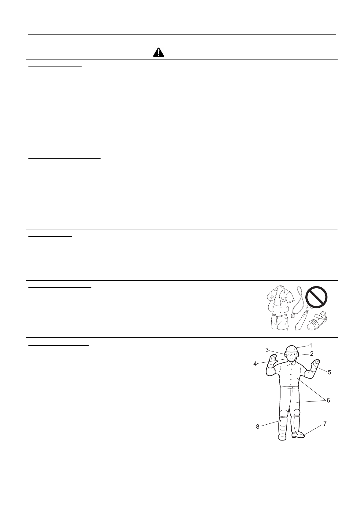
Wear proper clothing.
Secure hair so it is above shoulder length.
Do not wear ties, jewellery, or loose, dangling clothing which could be caught in the
unit.
Do not wear open toed footwear, or go bare-foot or barelegged.
Failure to observe these precautions could result in damage to your sight or hearing, or lead
to a serious injury.
Wear protective gear
Always wear the following protective gear when working with the trimmer.
1. Head protection (helmet): Protects the head
2. Ear muffs or ear plugs: Protect the hearing
3. Safety goggles: Protect the eyes
4. Face shield: Protects the face
5. Safety gloves: Protect the hands from cold and vibration
6. Work clothes that fit (long sleeves, long trousers): Protect the body
7. Heavy duty, non-slip protective boots (wi th toecaps) or non-sli p work shoes
(with toecaps): Protect the feet
8. Shin guards: Protect the legs
Failure to observe th ese p recaut ion s cou ld res ult in dama ge to your s ight or heari ng, or
lead to a serious injury.
When necessary, please use the protective gear below.
Dust mask: Protects the breathing apparatus
Bee net: To deal with attacks by bees
4

For safe use of your product
WARNING
Environment of use and operation
Do not use the product:
under poor weather conditions.
on steep slopes or in places which give no secure foothold and are thus slippery.
at night or in dark places with poor visibility.
When using the product on a gentle slope, work in a level, contour-like motion.
A serious injury could result if you fall or slip, or fail to operate the product correctly.
For your own health and your safe and comfortable work, operate the machine within the air temperature range of -
o
C to 40 oC.
5
Failure to observe these instructions could result in damage to your health.
Being prepared in case of an injury
In the unlikely event of an accident or injury, please ensure that you are
prepared.
First aid kit
Towels and wipes (to stop any bleeding)
Whistle or mobile phone (for calling outside help)
If you are unable to perform first aid or call for outside help, the injury could
worsen.
Put safety first in the case of fire or smoke
If fire comes from the engine or smok e appears from any area other tha n the exhaust vent, first distance
yourself from the product to ensure your physical safety.
Use a shovel to throw sand or other such materia l on the fi re to prev ent it from sprea ding , or put it out
with a fire extinguisher.
A panicked reaction could result in the fire and other damage becoming more extensive.
Warning notices
DANGER WARNING CAUTION
This symbol accompanied by the
word "DANGER" calls attentions to
an act or a condition which will lead to
serious personal injury or death of operators and bystanders.
Other indicators
Circle and slash symbol means whatever is
shown is prohibited.
Symbols
Symbol form/shape Symbol description/applica-
This symbol accompanied by the
word "WARNING" calls attentions to
an act or a condition which can lead to
serious personal i njury or death o f operators and bystanders.
This enclosed mes sage pro vides tips
for use, care and mai nte nan ce of the
product.
tion
"CAUTION" indicates a potentially
hazardous situation which, if not
avoided, may result in minor or moderate injury.
NOTE IMPORTANT
Framed text featuring the word "IMPORTANT" contains important in for-
mation about the use, checking,
maintenance a nd storag e of t he product described in this manual.
Symbol form/shape Symbol description/applica-
tion
Carefully read the operator's
manual
Wear eyes, ears and head
protection
The maximum speed of the
cutting attachment shaft in
r/min
Keep bystanders away 15 m
5

For safe use of your product
Symbol form/shape Symbol description/applica-
tion
Wear foot protection and
gloves
Emergency stop
Warning!
Thrown objects!
Warning, side thrust
Usage without shield not permitted
Symbol form/shape Symbol description/applica-
tion
Petrol and oil mixture
Choke Control "Cold Start"
Position (Choke Closed)
Choke Control "Run" Position
(Choke Open)
Carburettor adjustment
- Idle speed
Beware of high-temperature
areas
Usage of metal blades not
permitted
Do not use the produc t in places with poor ventilation
Beware of fire Beware of electric shocks
Guaranteed sound power level
Engine start
6
For safe use of your product
Safety decal(s)
The safety decal shown below has been attached to the products described in this manual. Ensure that you understand what
the decal means before using your product.
If the decal bec omes unreada ble due to wea r and tear or damage, or peels off an d is lost, plea se purchase a replaceme nt decal
from your dealer and attach it in the location shown in the illustrations below. Ensure that the decal is readable at all times.
1. Safety decal (Part number X505-000140)
2. Safety decal (Part number X505-002310)
7
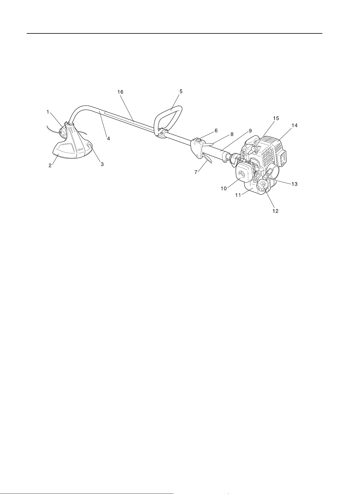
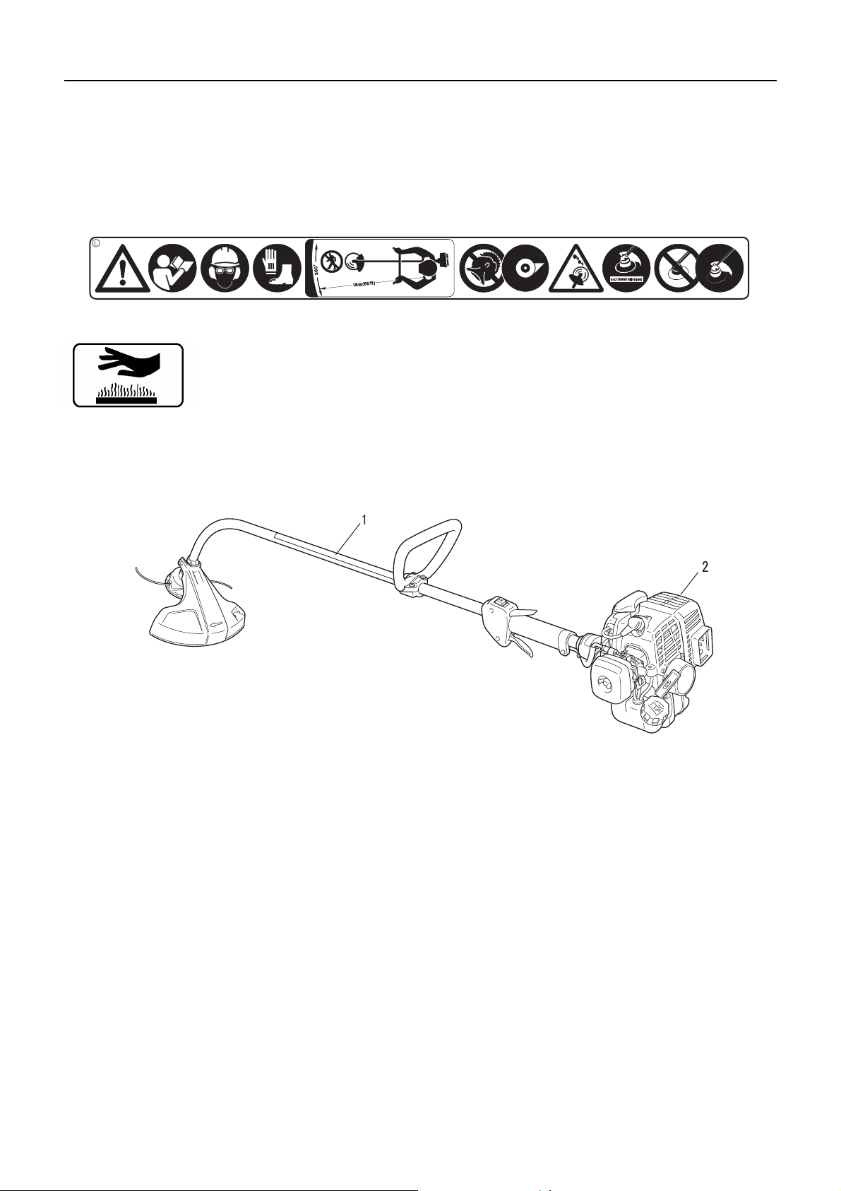
Description
Description
1. Cutting attachment Nylon line cutting head for cutting
grass and weed.
2. Shield Device to protect the operator from accidental
contact with the cutting head and thrown objects.
3. Cut off kn ife Cut nylon line to adj ust line length to prop er
swath.
4. Shaft tube Pa rt of the unit that provides a casi ng for po wer transmission shaft.
5. Loop-handle Light we ight, suitable for nylon line trimmer.
6. Ignition switch "Slide switch" mounted on top of the
throttle trigger housing, move switch forward to RUN,
backward to STOP position.
7. Throttle trigger Activated by the o perator's finger fo r controlling the engine speed.
8. T hrottle trigger lockout Locks thro ttle trigger in the idling
position until you have a proper gri p with your right hand
around the handle.
9. Grip Rear (right hand) handle.
10. Air cleaner cover Covers air filter.
11. Fuel tank Contains fuel and fuel filter.
12. Fuel tank cap For closing the fuel tank.
13. Starter handle Pull handle to start the engine.
14. Silencer cover Cover the si lencer not to make ope rator
touch to hot surface of silencer.
15. Spark plug
16. Safety decal
8

Before you start
Packing list
The following parts are packed separately in the packing box.
When you have unpacked the box, please check the parts that it contains.
Contact your dealer if anything is missing or broken.
Before you start
1. Engine and shaft tube
2. Wing nut
3. Washer
4. Bolt
5. Shield
6. Nylon line cutting head
7. Operator's manual
8. Loop handle
9. Safety goggles (ANSI Z 87.1 compliant)
10. Caution tag
11. Locking tool
12. Socket wrench
13. L-wrench
Assembly
WARNING
Read the operator's manual carefully to ensure that you assemble the product correctly.
Using a product that has been incorrectly assembled could lead to an accident or serious injury.
Loop handle assembly
Position handle (A) in comfortable operating position and tighten
screws (M5×35) (B). The cu tting attac hment sh ould be 5 - 7.5 cm
above the ground and as level as possible.
9
Before you start
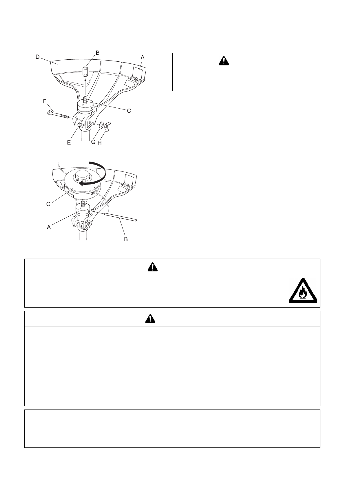
Installation of shield
Installing nylon line cutting head
WARNING
Cut off Knife (A) on debris shield has sharp edges.
Avoid contact when installing or removing line head.
Failure to do so could lead to an injury or serious accident.
1. Remove plastic sleeve (B) from output shaft (C).
2. Snap the shield (D) over the bearing housing (E).
3. Install bolt (F), washer (G) and wing nut (H).
1. Rotate output shaft until holes in fi xing pl ate (A) and in bearing housing are aligned.
2. Insert locking tool (B) through these holes.
3. Install nylon line head (C) to output shaft rotating clockwise.
4. Remove locking tool.
Preparing the fuel
DANGER
Do not fuel up while the engine is hot or in operation.
Do not smoke or hold a flame near when refuelling.
If you do so, the fuel could ignite and cause fire, leading to burns.
WARNING
Do not fill fuel tanks indoors. Alw ays fill fuel tanks outdoor s over bare ground. Do not refu el the product o n the loading platform of a truck, or in other such places.
Fuel tanks/cans may be under pressure. Always loosen fuel caps slowly allowing pressure to equalize.
Otherwise, fuel may get spewed.
Mop up any fuel that overflows or spills out due to overfilling.
Fuel spills can cause fire and burns when ignited.
After refuelling, always check that there are no leaks or discharges of fuel from the fuel pipe , fuel system grommets,
or around the fuel tank cap . If you do find fuel leaks or discharge s, stop using the product imme diate ly and contact
your dealer to have it repaired.
Any fuel leaks could cause fire.
Keep the refuelling tank in a shaded area away from fire.
Use an approved fuel container.
IMPORTANT
Fuel is a mixture of regular grade petrol an d an air-cooled 2-stroke engi ne oil of re putable brand name. Min imum 89 O c tan e
unleaded petrol is recommended. Do not use fuel containing methyl alcohol or more than 10 % of ethyl alcohol.
Stored fuel ages. Do not mix more fuel than you expect to use in thirty (30) days.
10

Fuel
Fuel supply
Before you start
Recommended mixture ratio; 50 : 1 (2 %) for ISO-L-EGD
Standard (ISO/CD 13738), JASO FC,FD grade and Shindaiwa
One 50 : 1 oil.
Do not mix directly in engine fuel tank.
Do not add so much fuel that it reaches the mouth of the fuel
tank (A). Keep the fuel within the prescribed level (up to the
shoulder level (B) of the fuel tank).
Tighten the fuel tank cap securely after refuelling.
11
Engine operation
Engine operation
Starting the engine
WARNING
Be particularly careful to observe the following precautions when starting the engine:
Move at least 3m from the place where you refueled.
Place the product in a flat, well ventilated place.
Check that there are no fuel leaks.
Check that none of the nuts and bolts are loose.
Leave plenty of space around the product and do not allow people or animals near it.
Start the engine with the throttle trigger in the idle speed position.
Hold the product firmly to the ground when starting the engine.
Failure to observe the precautions could cause an accident or injury, or even lead to a fatality.
Check that there are no abnormal vibrations or sounds once the engine starts. Do not use the product if there are
abnormal vibrations or sounds. Contact your dealer to have it repaired.
Accidents involving parts that fall or shatter off can cause wounds or serious injury.
The exhaust fumes from the engi ne contain toxic gases. Do not opera te the product indoo rs or in other
ill ventilated places.
The exhaust fumes could cause poisoning.
Do not touch silencer, spark plug, angle transmission, and other high temperature components while
the product is running or for some time after it stops.
You could burn yourself if you touch a high temperature component.
Do not touch spark plug, spark plug wire, and other high voltage co mpon ents while the produc t is run-
ning.
You could receive an electric shock if you touch a high voltage component while the product is running.
If the cutting attachment rotates even though the throttle trigger is in the idle speed position when the engine is started, adjust the carburettor before using the product.
Failure to observe the precautions could cause an accident or injury, or even lead to a fatality.
NOTE
Pull out the starter grip gently at first, and then more rapidly. Do not pull the starter rope out to more than 2/3 of its length.
Do not let go of the starter grip as it returns.
Starting a cold engine
(Connect the spark plug cap if the produ ct has been i n storage fo r
a long period of time.)
1. Placing the product on l evel ground, check to ensure that the
cutting attachment does not come into contact with the surface of the groun d or a ny other im pediment using a beam or
other such implement.
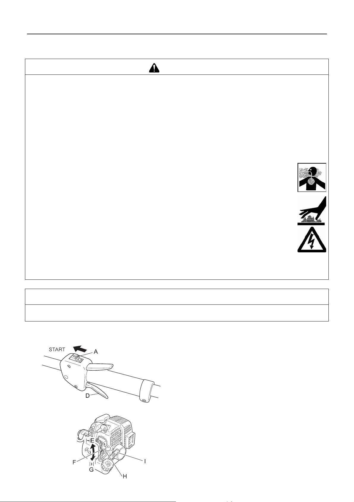
2. Move the ignition switch (A) to the Start position.
3. Make sure that the throttle trigger (D) is at the idle speed position.
4. Move the choke lever (F) to the "Cold Start" (E) position.
5. Alternately press an d release the purge bulb (H) until the fuel
is sucked up into it.
6. Checking that the area aro und yo u is s afe, ho ld the posit ion
closest to the engine firmly as shown in the illustration, pulling several times on the starter grip (I).
7. If you hear an explosion-like sound and the en gine stops im mediately, move the choke lever to the "Run" (G) position
and continue pulling on the starter grip to start the engine.
8. If the engine does not stop, return the choke lever gently to
12
Starting a warm engine
Engine operation
the "Run" position.
9. Leave the engine to warm up at idle speed for a while.
1. Move the ignition switch (A) to the Start position.
2. Make sure that the throttle trigger (D) is at the idle speed position.
3. Check that the choke lever is in the "Run" position.
4. If no fuel is visible in the purg e bulb, alterna tely press a nd release the purge bulb until the fuel is sucked up into it.
5. Checking that the area aro und yo u is s afe, ho ld the posit ion
closest to the engine firmly, and pull on the starter grip to
start the engine.
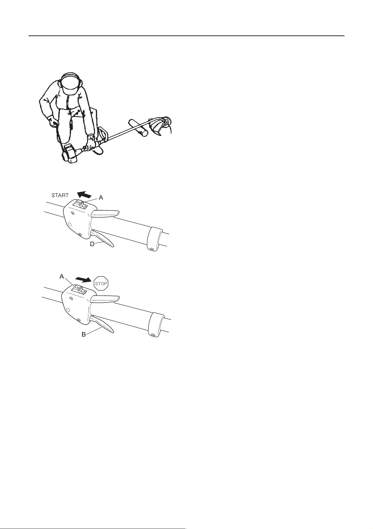
Stopping the engine
1. Move the throttle trigger (B) to the idle speed position and set
the engine to idling (i.e. low speed).
2. Move the ignition switch (A) to the Stop position.
3. In the event of an emergency, stop the engine immediately
using the ignition switch.
4. If the engine fails to sto p, move the choke lever to t he "Co ld
Start" position. The engine will stall and come to a halt (an
emergency stop).
∗ If the en gine fails to stop w hen the ignition sw itch is used, have
the ignition switc h checked and rep aired by your deale r before
you use the product again.
5. Always disconnect the spark plug wire from the spark plug to
ensure the engine cann ot be st arted before y ou work on th e
unit or leave it unattended.
13

Trimming operation
Trimming operation
DANGER
Always stop the engine when a cutting attachment jam occurs.
Severe injury can occur if a jam is removed and the cutting attachment suddenly starts.
Do not operate the product without the shield in place.
Any objects that ricochet off the cutting attachment could cause an accident or serious injury.
The area within a 15 m radius of the pro duct is a dang er zone. B e careful to observe the following precautions while working with the product.
Do not allow children and other people or pets to enter the danger
zone.
If another person enters the danger zone, turn off the engine to stop
the cutting attachment from rotating.
When approaching the operator, signal to him by, for example,
throwing twigs from outside the danger zone, and then check that
engine has been switched off and the cutting attachment has
stopped turning.
If more than one person is working with the product, identify the way
in which you will signal to each other and work at least 15 m apart.
Any objects that ricoc he t off the cu tting attachment, and an y c ontact with the cuttin g a ttac hm en t, co uld cause blindness or a
fatal accident.
WARNING
Before starting work, check the a rea where you will be working and remove any s mall stones
and empty cans likely to ricochet off the cutting attachment, as well as any pie ces of stri ng
or wire that might become twisted around the cutting attachment.
An accident or serious injury can occur if f orei gn objects ricochet off the cutting attach ment or wire
and other materials twisted round the product spring off it.
In the following situations, turn off the engine immediately and ensure that the cutting attachments have stopped
before checking each area of the product. Replace any damaged parts.
If the cutting attachment hits a rock, tree, post, or other such obstruction while you work.
If the product suddenly starts to vibrate abnormally.
Continuing to use parts w hen they are d amaged could lead to an acci dent or serious injury.
Do not hold the cutting attachment up while yo u work. You must not work with the cutting atta chments raise d above
knee level.
Raising the cut ting a ttachm ent a bove knee lev el bri ngs t he pl ane o f r otation clo ser to the face, and any o bject s tha t f ly of f the
cutting attachments could cause an accident or serious injury.
Transport of the product
When transporting in the sit uations describ ed below, turn off the engine and ensure tha t the cutting attac hment has
stopped rotating, then position the silencer away from yourself.
Moving to the place where you are working.
Moving to another area while you are working.
Leaving the place where you have been working.
Failure to observe these precautions could cause burns or serious injury.
When transporting the product by car, empty the fuel tank and secure the product firmly in place to prevent it from
moving around.
Travelling by car with fuel in the fuel tank could lead to a fire.
Never attempt to operate the product with one hand.
Ensure that you hook your thumbs around th e grips, w rapping them in y our thumb
and remaining fingers.
14
Trimming operation
Basic trimming operation with nylon line cutting head
WARNING
Serious injury may result fro m the improper use of cu tting attach ment. Read and com ply with all safety ins tructions
listed in this manual.
Use only cutting attachments recommended by YAMABIKO CORPORATION.
Excessive nylon line beyond cut off knife could fly off when the nylon line cutting head starts rotating after adjustment of nylon line length.
Failure to do so could lead to an accident or serious injury.
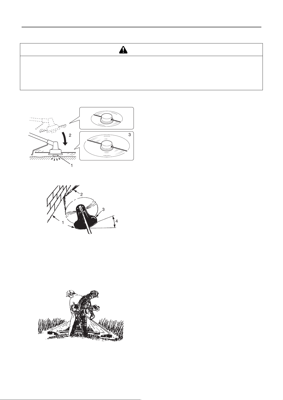
Adjusting nylon line
Do not rotate the nylon line cutti ng head at more than 10000 r/
min.
When releasing nylon line from spool, hit tap knob of spool
against the gro und surface lightly at rotati on spee d lower th an
4500 r/min.
Cut off knife on th e s hie ld a dju sts cutting swath au tom ati cal ly
by cutting nylon lines evenly when attachment starts rotating.
When operating with less than maximum cutting swath, cut
two nylon lines in equal lengths.
1. Tap knob
2. Hit knob against the ground surface lightly
3. Nylon line comes out
Trimming
Scything
This is feeding the trimmer caref ully into the mater ial you wish
to cut. Tilt the head sli ghtly to direct th e debris away fr om you.
If cutting up to a barri er such as a fence , wall or tree, approach
from an angle whe r e a ny de bris ri co che ting off the barrier wi ll
fly away from you.
Move the nylon line cutting head slowly until the grass is cut
right up to the barrier, but do not jam (overfeed) the line into
the barrier. If trimming up wire mesh or chain link fencing, be
careful to feed only u p to the wire. If y ou go too far, th e line will
snap off around the wire.
Trimming can be done to cut through weed stems one at a
time. Place the nylon line cu ttin g hea d near the bottom of the
weed never high up, which could cause the weed to chatter
and catch the line. Rather tha n cut the weed right through , just
use the very end of the line to wear through the stem slowly.
1. Angle to wall
2. Debris
3. Knife side raised
4. Angle to ground
This is the cutting or mowing of large grassy areas by sweep-
ing or swinging the trimmer in a level arc. Use a smooth, easy
motion. Do not try to ha ck or c ho p d own th e g r as s. T ilt the ny lon line cutting head to direct the debris away from you on the
scything stroke. Then return w it hou t cutt ing gras s for an oth er
stroke. If you a re well protected and do not ca re whether some
debris is thrown in your direction, you may scythe in both directions.
15

Trimming operation
Scalping and edging
Both of these are done with the nylon line cutti ng head tilted at
a steep angle. Scalp ing (A) is removing top growth, leaving the
earth bare. Edging (B) is trimming the grass back where it has
spread over a pavem ent o r drive way. During both ed ging a nd
scalping, hold the unit at a steep angle in a position where the
debris, and any dislodged dirt and stone, will not come back
towards you even if it ricochets off the hard surface.
Although the pictures show how to edge and scalp, every op-
erator must find for himself the angles which suit his body size
and cutting situation.
For nearly all cutting, it is good to tilt the nylon line cutting he ad
so that contact is m ade on th e part of li ne circle where th e line
is moving away from you and the shield (See appropriate picture). This results in the debris being thrown away from you.
Tilting the head to the wron g side wil l shoot the debris to ward
you. If the nylon line cutting head is held flat to the ground so
that cutting occurs on the whole line circle, debris will be
thrown at you, drag wil l slow th e engine, an d you will us e up a
lot of line.
Nylon line cutting head ro tates c lock wise. T he kni fe wil l be on
the right side of the shield.
1. Debris
2. Cut on this side
Do not push the line into tough weeds, trees, or wire fences.
Pushing the line into chicken wire, chain link fencing or thick
brush can result in snapp ed-off lin e ends be ing hurled back at
the operator. The proper way is to cut right up to a barri er, such
as any of those mentioned, but never run the line into or
through the obstruction. Do not cut closely to obstruction or
barrier.
Avoid nylon line contact with broken wire fencing. Pieces of
wire broken off by the trimmer can be hurled at high speeds.
16

Maintenance and care
Maintenance and care
WARNING
Observe the following precautions when checking and maintaining your product after use:
Turn the engine off and do not attempt to check or maintain the product until the engine has cooled.
You could burn yourself.
Remove the spark plug cap before performing checks and maintenance.
An accident could occur if the product starts unexpectedly.
IMPORTANT
Checking and maintenance requires special ist knowled ge. If you are unabl e to check and maintain the pro duct or deal with a
fault yourself, consult your dealer. Do not attempt to dismantle the product.
Servicing guidelines
Area Maintenance Page Before use Monthly
Air filter Clean/Replace 17 •
Fuel filter Inspect/Clean/Replace 18 •
Spark plug Inspect/Clean/Adjust/Replace 19 •
Carburettor Adjust/Replace and adjust 18 •
Cooling system Inspect/Clean 18 •
Silencer Inspect/Tighten 19 •
Silencer Clean 19 •**
Drive shaft Grease 20 •*
Starter Inspect - •
Cut off knife Inspect/Clean - •
Fuel system Inspect 18 •
Screws, bolts and nuts Inspect, Tighten/Replace - •
* Or 50 hours, whichever occurs first. ** Or 100 hours, whichever occurs first.
IMPORTANT
Time intervals are maximum. Actual use and your experience will determine the frequency of required maintenance.
Maintenance and care
If you have any questions or problems, please contact your dealer.
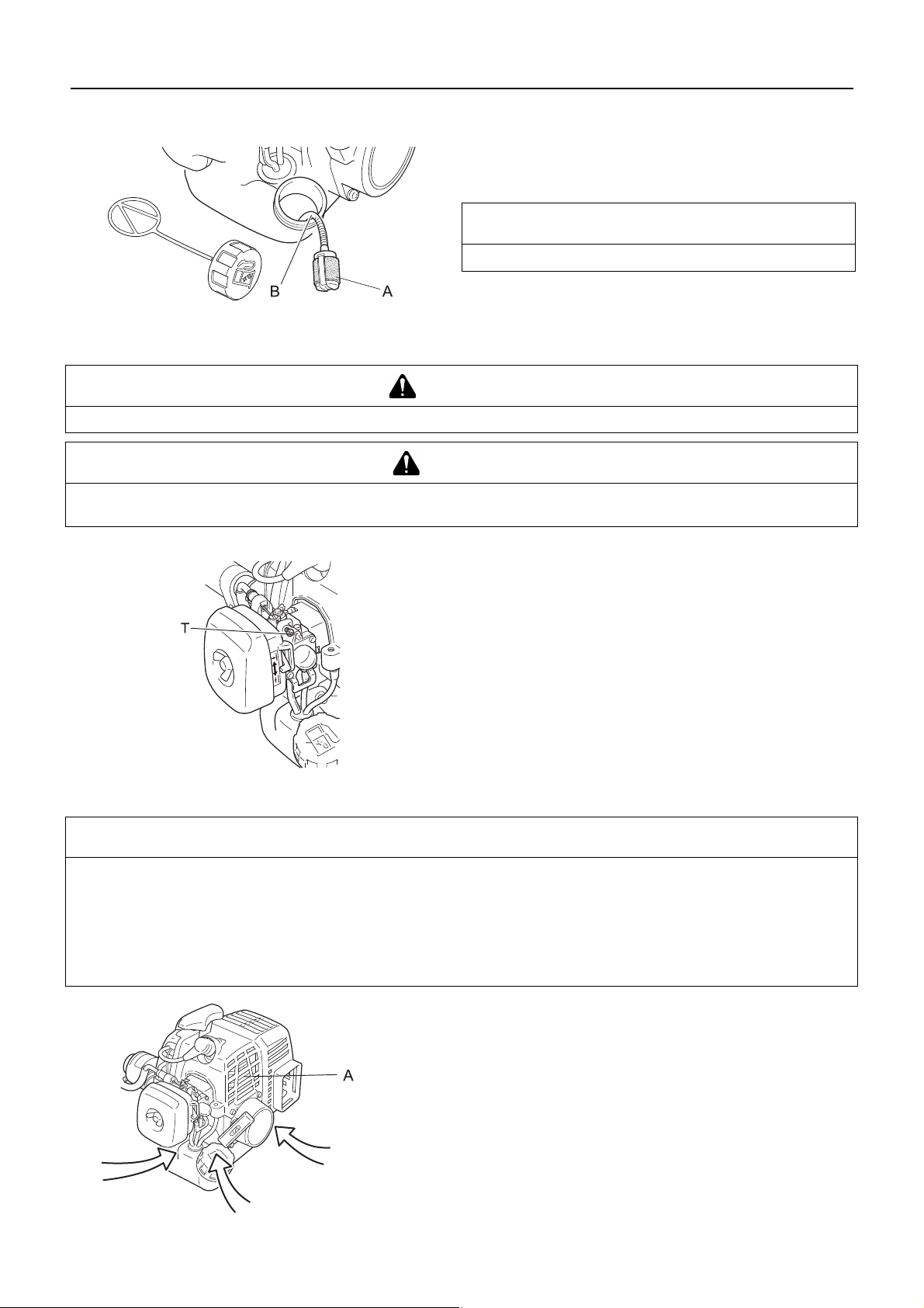
Cleaning air filter
Close choke. Loosen wing bolt (A) and remove air cleaner
cover (B).
Remove air filter (C) (air filter is loc ated in side ai r cleane r cov-
er).
Brush dirt from filter or clean with compressed air.
Reinstall filter.
Reinstall cover and tighten wing bolt.
17
Maintenance and care
Replacing fuel filter
1. Use a piece of metal wire or the like to pick up fuel filter (A)
through fuel tank opening.
2. Pull old filter from fuel line (B).
3. Install new fuel filter.
NOTE
If filter is excessive dirty or no longer f its properl y, replac e it.
Carburettor adjustment
WARNING
When the carburettor is being adjusted, the cutting attachment may move. Be careful not to get injured.
CAUTION
When starting, idle speed adjustment screw (T) should be adjusted not to rotate the cutting attachment.
When there is some trouble with the carburettor, contact your dealer.
Every unit is test run at the factory and the carburettor is fine
tuned for maximum performance.
Before adjusting carburettor, clean or replace air filter, start engine and run several minu tes to bring i t to operating temperature .
To adjust the carburettor proceed as follow:
Turn "idle" speed a djustment s crew (T) clockwis e until cutti ng
atttachment begins to turn, then turn screw(T) out anticlockwise until cutting attachment stops turning. Turn screw (T)
out, anticlockwise, and additional 1 turn.
Cooling system maintenance
IMPORTANT
To maintain proper engine operating temperature, cooling air must pass freely through the cylinder fin area. This
flow of air carries combustion heat away from the engine. Overheating and engine seizure can occur when:
Air intakes are blocked, preventing cooling air from reaching the cylinder,
Dust and grass build up on the outside of the cylinder. This build-up insulates the engine and prevents the heat
from leaving.
Removal of cooling passage b lockages or cleanin g of cylin der fins is con sidered "N ormal Ma intenanc e". Any re sultant fa ilure
attributed to lack of maintenance is not warranted.
Remove dust and dirt from between fins (A).
Before each use, rem ove accum ulated de bris from bottom en-
gine intake grille located between the fuel tank and starter.
Airintake
18
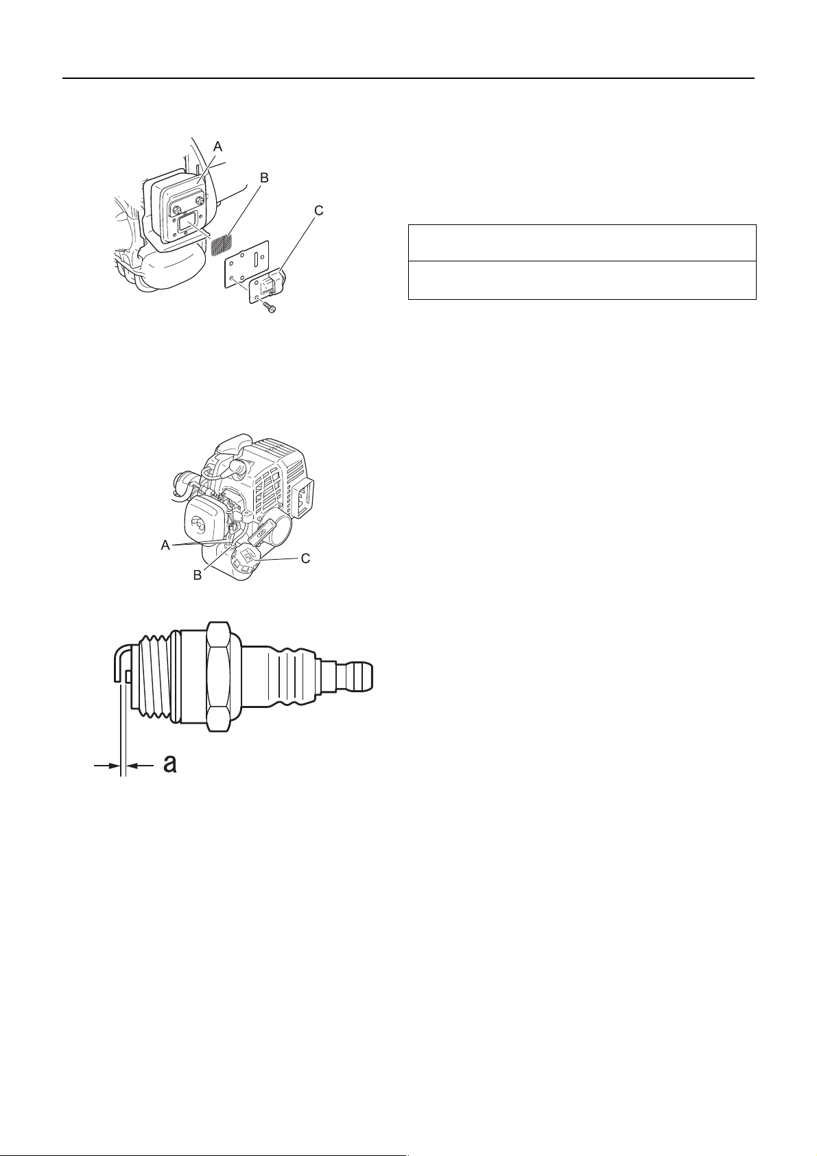
Cleaning silencer
Check fuel system
Maintenance and care
1. Remove the silencer cover.
2. Remove the spark arrester screen cove r (C) and the scree n
(B) from the silencer body.
3. Clean carbon deposits from silencer components (A).
4. Replace the screen if it is cracke d, or has hole s burned
through.
5. Assemble the components in reverse order.
NOTE
Carbon deposits in silencer will cause drop in engine out-
put.The spark arrester scre en must be checked perio dically.
Check before every use.
After refuelling, make sure fuel does not leak or exude from
around fuel pipe (A), fuel grommet (B) or fuel tank cap (C).
In case of fuel leakage or exuda tio n, there is a danger of fire.
Stop using the machine im me diately and request your dealer
to inspect or replace.
Check spark plug
1. Check plug gap. Correct gap is 0.6 mm to 0.7 mm.
2. Inspect electrode for wear.
3. Inspect insulator for oil or other deposits.
4. If the electrodesor termina ls are w o rn, o r if there are cracks
in the ceramics, replace them with new parts.
5. Tighten to 15 N·m - 17 N·m (150kgf·cm to 170 kgf·cm).
∗ The spark test (for checking whether the spark plug is spark-
ing) must be carried out by your dealer.
a:0.6‑0.7mm
19
Maintenance and care
Lubricating drive shaft
1. Remove shield (A).
2. Loosen bearing housing (B) lo cating scre w, a t the top o f the
housing, remove mounting screw.
3. Pull flexible shaft (C) from the shaft tube (D), wipe clean and
recoat with a thin c oating 10 to 20 g , of li thium base g rea se.
4. Slide the flexible shaft back in the shaft tube. DO NOT get
dirt on the flexible shaft.
5. Install the bearing housing and shield.
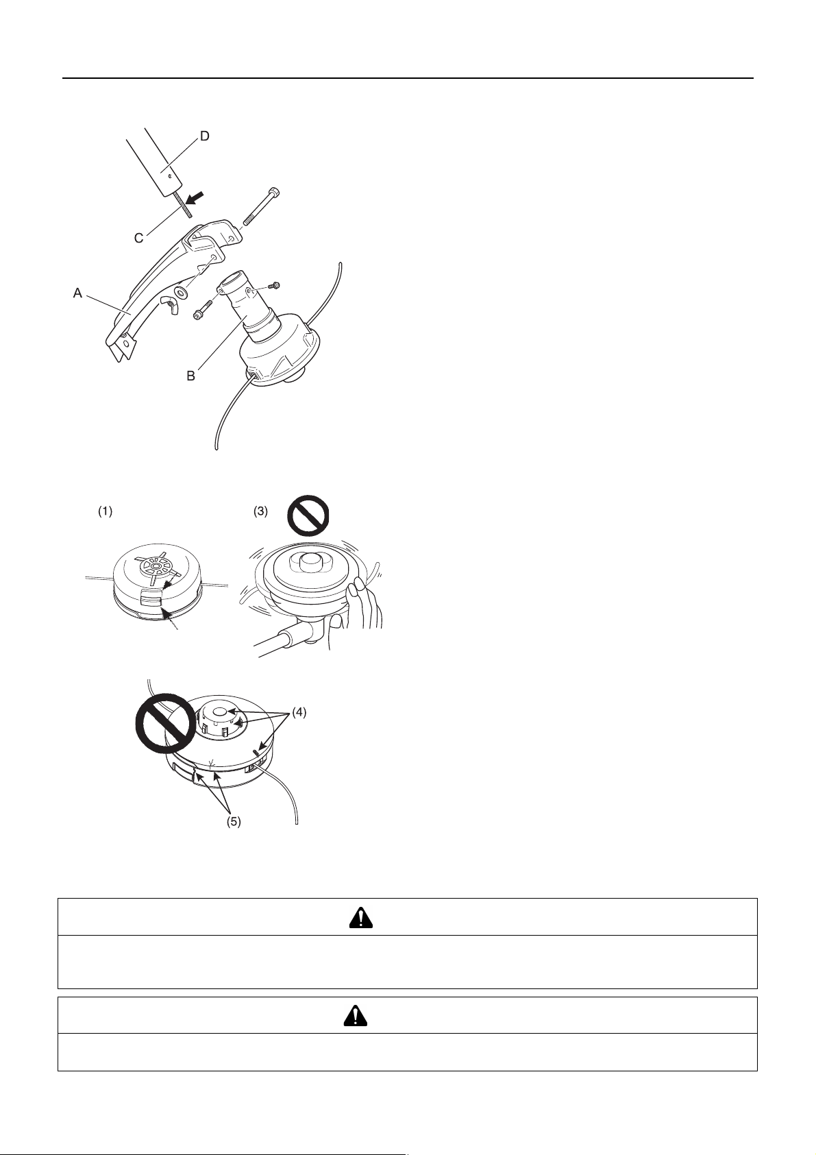
Checking the nylon line cutting head
Replacing nylon line
1. Make sure each periphery of the 2 retaining pawls of housin g
spreads almost fully up to the oute r perip hery of the respective cover window.
2. Check mount of cutting head on trimmer and tighten if it is
loose.
3. Check the cutter head for deflecti on or abnorm al noise rotating it by hand. Deflection or abnormal noise can cause abnormal vibration to occur or mount to trimmer to loosen
during rotation which is dangerous.
4. Inspect cover and tap kn ob fo r w ea r. Whe n s lot appears on
bottom of the tap knob o r when slot appears on cov er bottom
close to outlet for nylon line, replace them with new parts
without fail.
5. Check the cutting head for crac k or chip . Replac e parts tha t
show any crack or chip with new ones without fail.
DANGER
Shut down trimmer engine without fail and make sure nylon line cutting head has stopped rotating before starting
replacement procedure.
To do so could lead to an accident or serious injury.
WARNING
Use only flexible, non-metallic line recommended by YAMABIKO CORPORATION.
Failure to do so could lead to an accident or serious injury.
20
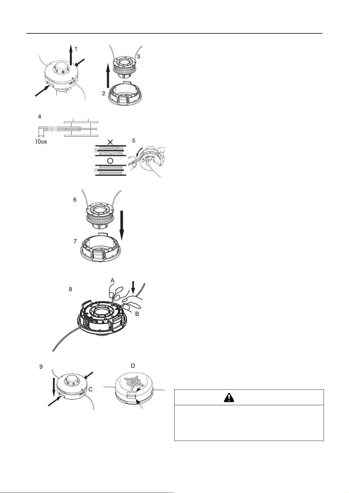
Maintenance and care
1. Press "retaining pawls" (at two places) inward and remove
cover. It is easier to remove one after another.
2. Remove spool.
3. When nylon line on the spool is almost exhausted, remove
remaining line from spool and wind "new line" according to
the procedures (4) and beyond. When the line on the spool
is "melted and stuck " remove the e ntire line wh ile peeling of f
the "melted and stuck" portion and wind the "removed line"
anew according to procedures (4) and beyond.
4. Bend the line at the point 10 cm away from the middle of
whole length and ho ok the bent portion in to the "notch" o f the
intermediate separator.
5. Wind the line firmly into groove of the spool following "winding direction for the line R".
6. When the line is wound to the end hook both line ends into
respective notch of spool for retaining tentatively the line
while leaving line ends approximately 10 cm beyond notch.
7. Align notches of spool for the line with grooves of eyelets
and fit spool into housing.
8. Pull out the line from housing. (A) Remov e th e lin e fro m "re spective notch of spool", and (B) pass it through "groove of
respective eyelet".
9. Fit cover and housing together. (C) Align "eyelets" of cover
with "recesses" of housing, and (D) press pawls of housing
into respective window of cover until the pawls are firmly fitted into the windows.
DANGER
Make sure each outer periphery of pawls of housing
spreads almost fully up to the outer periphery of respective window of cover.
If they are loosely fitted and th e cutting head is turned, co ver
or inside components can fly off which is dangerous.
21

Maintenance and care
Troubleshooting table
IMPORTANT
For spare parts and consumables, please use only genuine parts and designated products and components.
Using parts from other manufacturers or non-designated components may result in a malfunction.
Problem Diagnosis Cause Solution
The engine does
not start
Engine is difficult to
start, fluctuating rotation
Engine starts but
no acceleration is
possible
The engine stops 1. Carburettor adjustment problem
The engine fails to
stop
Cutting attachment
rotates when the
engine is idling
Fuel is entering the overflow
pipe
No fuel is entering the overflow pipe
The spark plug is dirty or
damp
1. There is no fuel in the fuel tank
2. The stop switch is in the Stop position
3. Excess fuel suction
4. Electrical fault
5. Carburettor malfunction or intern al sticking
6. Internal engine malfunction
1. Fuel degradation
2. Carburettor problem
1. Fuel filter is clogged
2. Fuel system is clogged
3. Internal carburettor parts sticki ng
1. Fuel degradation
2. Incorrect electrode gap
3. Carbon deposits
4. Electrical fault
1. Dirty air filter
2. Dirty fuel filter
3. Blocked fuel passage
4. Carburettor adjustment problem
5. Blocked exhaust vent or silencer vent
2. Electrical fault
1. Stop switch malfunction 1. Perform an emergen-
1. Carburettor adjustment problem
2. Damaged clutch spring
1. Fuel supply
2. Move to the Start position
3. Start the engine after
servicing
4. Consult your dealer
5. Consult your dealer
6. Consult your dealer
1. Replace with new fuel
2. Consult your dealer
1. Clean or replace
2. Consult your dealer
3. Consult your dealer
1. Replace
2. Replace
3. Replace
4. Consult your dealer
1. Clean or replace
2. Clean or replace
3. Consult your dealer
4. Adjust
5. Clean
1. Adjust
2. Consult your dealer
cy stop and consult
your dealer
1. Adjust
2. Consult your dealer
Consult your dealer in the event of a problem that is not covered in the table above, or other such concerns.
Please contact your dealer in order to dispose of the product or its parts in compliance with national laws.
Manufacturer:
YAMABIKO CORPORATION
7-2 SUEHIROCHO 1-CHOME, OHME, TOKYO 198-8760, JAPAN
Authorized Representative in Europe:
Atlantic Bridge Limited
Atlantic House, PO Box 4800, Earley, Reading RG5 4GB, United Kingdom
22

Maintenance and care
Storage
Long-term storage (30 days or more)
WARNING
Do not store in sealed locations filled with fuel gas, or close to naked flames or sparks.
You could cause a fire.
When storing the pr oduct for long periods of time (3 0 days or more), e nsure that the following preparat ions for stor age are carried
out.
1. Remove any fuel from the fuel tank.
2. Alternately press and release the purge bulb a number of
times to remove the fuel from the purge bulb.
3. Start the engine and run it at idle speed until it comes to a
natural stop.
4. Move the ignition switch (A) to the Stop position.
5. Once the product is sufficiently cool, wipe clean any grease,
oil, dust, dirt and other materials on the outside of the trimmer.
6. Perform the periodic checks prescribed in this manual.
7. Check that the screws and nuts are tightened. Tighten up
any that are loose.
8. Remove the spark plug (B) and add th e appropriate qu antity
(around 10 mL) of clean, new 2-stroke engine oil to the cylinder via the installation socket.
9. Place a piece of clean cloth over the spark plug installation
socket.
10. Pull 2 or 3 times on the s tarter grip to distribute the engine oil
into the cylinder.
11. Observe the piston location throu gh the spark pl ug hole. Pull
the recoil starter handle slowly until the piston reaches the
top of its travel and leave it there.
12. Fit the spark plug. (Do not connect the spark plug cap (C). )
13. Wrap the engine section in a plastic bag or other covering,
and store in a dry, d ust-free loca tion out of reac h of children .
23

Specifications
Specifications
F226S
External dimensions:
Length × Width × Height mm 1460 × 320 × 575
Mass:
Unit without cutting attachment and shield (ISO 11806)
Unit with fuel, specified cutting attachment, shield and
harness
Volume: Fuel tank L 0.4
Cutting attachment:
Nylon line cutting head
Line diameter
Line length
Thread
Gear ratio: Gear ratio and lubrication 1 good quality lithium grease
Rotational direction of output s haft s ee n from abo ve: clockwise
Engine:Type Air cooled 2-stroke single cylinder
Engine displacement
Maximum shaft brake power, measured in accordance
with ISO 8893
Engine speed at maximum engine power
Recommended engine idling speed
kg
kg
mm
m
mL (cm
kW
r/min
r/min
4.3
5.1
G137
3.0
2 ×1 line
Right-handed thread 3/8×24UN F
3
)
21.2
0.71
8000
3000
Recommended maximum engine speed (With STD at-
tachment installed)
Carburettor
Ignition
Spark plug
Starter
Clutch
Fuel:
Oil
Ratio
Fuel consumption at maximum engine power
Specific fuel consumption at maximum engine power
Sound pressure level: (ISO 22868) L
Guaranteed sound power level:(ISO 22868) L
Vibration levels: (ISO 22867)a
pAeq
WA
hv,eq
These specifications are subject to change without notice.
r/min 7200
Diaphragm type
Flywheel magneto - CDI system
NGK BPMR8Y
Recoil starter
Automatic centrifugal clutch
Regular grade petrol. Minimum 89 Octane unleaded
petrol is recommended. Do not use fuel containing
methyl alcohol or more than 10 % of ethyl alcohol.
Two stroke, air-coole d engine oil . ISO-L-EGD St andard (ISO/CD 13738), JASO FC,FD grade and
Shindaiwa One 50 : 1 oil.
50 : 1 (2%)
L/h
g/(kW•h)
0.45
469
dB(A) 91.9
dB(A) 108
2
m/s
m/s
2
Front hand le 4.9
Rear handle 5.4
24

The undersigned manufacturer:
YAMABIKO CORPORATION
7-2 SUEHIROCHO 1-CHOME
OHME; TOKYO 198-8760
JAPAN
declares that the hereunder specified new unit:
GRASS-TRIMMER
Brand: shindaiwa
Type: F226S
assembled by:
ECHO MACHINERY (SHENZHEN) CO., LTD
53 Block,Baotian Industrial Area,Bao-an District,Shenzhen City,Guang
Dong,China
Declaration of conformity
Declaration of conformity
complies with:
* the requirements of Directive 2006/42/EC
* the requirements of Directive 2004/108/EC (use of harmonized standard EN ISO 14982)
* the requirements of Directive 2010/26/EU
* the requirements of Directive 2000/14/EC
Conformity assessment procedure followed ANNEX V
Measured sound power level :105 dB(A)
Guaranteed sound power level :108 dB(A)
Serial Number 37001001 and up
Tokyo, April 1st 2012
YAMABIKO CORPORATION
The authorized representative in Europe who is authorized to compile the technical file.
Company: Atlantic Bridge Limited
Address: Atlanti c House, P O Box 480 0, Ear ley, Rea ding
RG5 4GB, UK
K. OYURI Mr. Philip Wicks
General Manager
25

1Notes and rear cover
MEMORANDUM
2012
X772-000830
X772227-5700
26

MEMORANDUM
2012
X772-000830
X772227-5700
27

7-2 SUEHIROCHO 1-CHOME, OHME, TOKYO 198-8760, JAPAN
PHONE: 81-428-32-6118. FAX: 81-428-32-6145.
©
2012
X772-000830
X772227-5700
Printed in Japan
0x0xxxx zzzz ES
28
 Loading...