

Shindaiwa F220,T220,C220 Owner's Manual

T220
C220
SHINDAIWA OWNER’S/OPERATOR’S MANUAL
F220 GRASS TRIMMER
T220 GRASS TRIMMER
C220 BRUSHCUTTER
Part Number 62090-94311 Rev. 6/06
• Read this manual and familiarize yourself with its contents.
• This machine is designed for cutting grass, weed, and brush.
Do not use this machine for other purposes.
• Minimize the risk of injury to yourself and others.
• Do not operate or service this machine unless you clearly understand this manual.
• Keep this manual available at all times so that you can reference it whenever you
have a question about its use.
WARNING!
F220
English...................1
Francais...............25
Italiano.................49
2
Contents
Introduction ................................................ 2
Attention Statements ................................. 2
Safety Information ..................................... 2
Safety Labels .............................................. 4
Unit Description ......................................... 4
Specifications .............................................. 5
Assembly ..................................................... 6
Mixing Fuel .............................................. 12
Starting the Engine .................................. 13
Stopping the Engine ................................ 14
Adjusting Engine Idle .............................. 14
Unit Condition Check .............................. 14
Shoulder Strap .......................................... 15
Using a Trimmer Head ............................ 15
Using a Blade............................................ 16
Maintenance ............................................. 17
Long Term Storage .................................. 19
Blade Sharpening .................................... 19
Troubleshooting Guide ........................... 20
Declaration of Conformity ....................... 22
Throughout this manual are special
“Attention Statements”.
Attention Statements
WARNING!
A statement preceded by the triangular
attention symbol and the word
“WARNING” contains information that
should be acted upon to prevent
serious bodily injury.
CAUTION!
A statement preceded by the word
“CAUTION” contains information that
should be acted upon to prevent
mechanical damage.
IMPORTANT!
A statement preceded by the word
“IMPORTANT” is one that possesses
special signicance.
NOTE:
A statement preceded by the word “NOTE”
contains information that is handy to know and
may make your job easier.
PAGE
Introduction
Shindaiwa 220 series hand held power
equipment has been designed and built to
deliver superior performance and reliability
without compromise to quality, comfort,
safety or durability.
Shindaiwa’s high-performance engines
represent the leading edge of 2-cycle
engine technology, delivering exceptionally
high power with remarkably low displacement and weight. As an owner/operator,
you’ll soon discover for yourself why
Shindaiwa is simply in a class by itself!
IMPORTANT!
The information contained in this
owner's/operator's manual describes
units available at the time of publication.
While every attempt has been made to give
you the very latest information about your
Shindaiwa product, there may be some differences between your machine and what
is described here. Shindaiwa Inc. reserves
the right to make changes to products
without prior notice, and without obligation to make alterations to units previously
manufactured.
IMPORTANT!
The operational procedures described in
this manual are intended to help you get the
most from the unit as well as to protect you
and others from harm. These procedures
are guidelines for safe operation under most
conditions, and are not intended to replace any
safety rules and/or laws that may be in force
in your area. If you have questions regarding
your Shindaiwa power tool, or if you do not
understand something in this manual, your
Shindaiwa dealer will be glad to assist you.
You may also contact Shindaiwa, Inc. at the
address printed on the back of this manual.
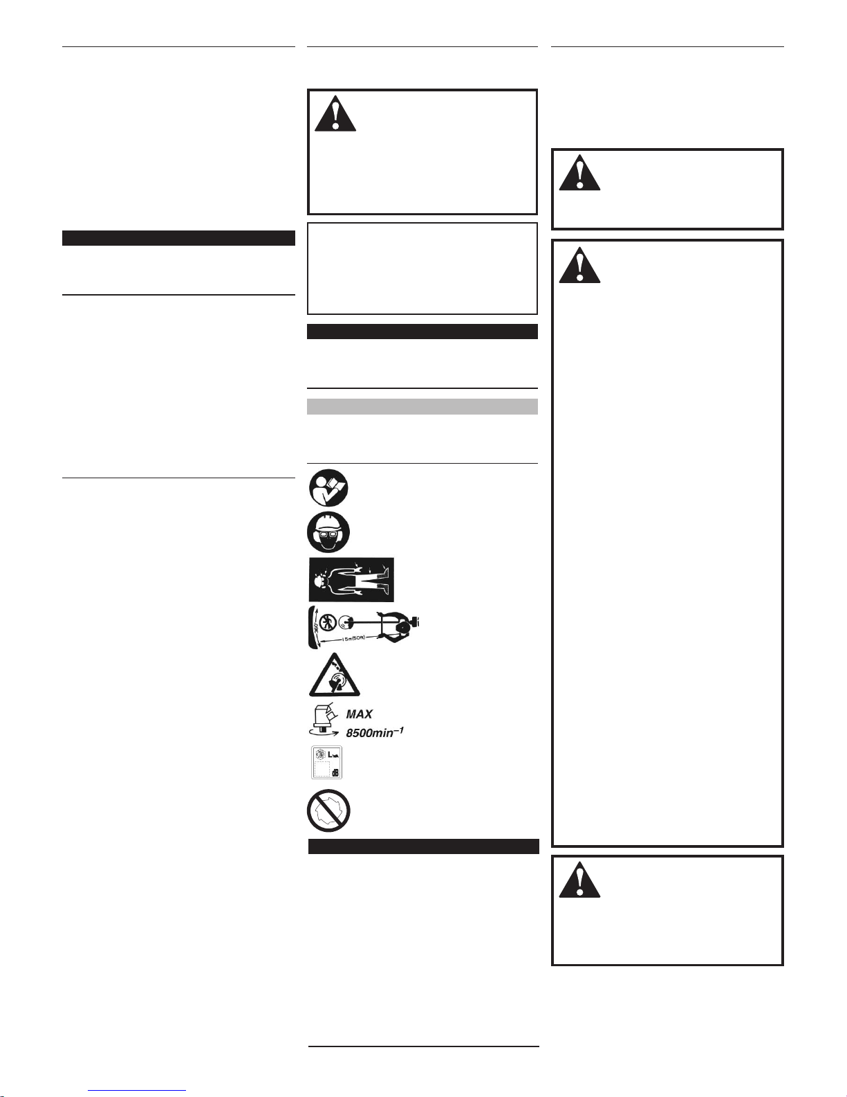
Read and follow this
operator's manual. Failure
to do so could result in
serious injury.
Wear eye and hearing
protection at all times during
operation of this unit.
Wear non-slip gloves, long
trousers and non-skid boots
during the operation of this
machine.
Make sure no one is within
15 meters of an operating
machine.
Beware of thrown objects.
The maximum speed of the
cutting attachment shaft in
min-1.
Sound Power Level
(measured in accordance
with 2000/14/EC).
DO NOT USE METAL
BLADES (F220 ONLY)
Work Safely
Trimmers and brushcutters operate at very
high speeds and can do serious damage or
injury if they are misused or abused. Never
allow a person without training or instruction to operate this unit!
WARNING!
Use Good Judgment
ALWAYS wear eye protection to shield
against thrown objects.
NEVER run the engine when
transporting the unit.
NEVER run the engine indoors! Make
sure there is always good ventilation.
Fumes from engine exhaust can cause
serious injury or death.
ALWAYS clear your work area of trash
or hidden debris that could be thrown
back at you or toward a bystander.
ALWAYS use the proper cutting tool
for the job.
ALWAYS stop the unit immediately if
it suddenly begins to vibrate or shake.
Inspect for broken, missing or improperly installed parts or attachments.
NEVER extend trimming line beyond
the length specied for your unit.
ALWAYS keep the unit as clean as
practical. Keep it free of loose
vegetation, mud, etc.
ALWAYS hold the unit rmly with both
hands when cutting or trimming, and
maintain control at all times.
ALWAYS keep the handles clean.
ALWAYS disconnect the spark plug
wire before performing any
maintenance work.
ALWAYS, if a saw blade should bind
fast in a cut, shut off the engine immediately. Push the branch or tree to ease
the bind and free the blade.
Safety Information
WARNING!
Never make unauthorized attachment
installations.
WARNING!
The engine exhaust from this product
contains chemicals which may cause
cancer, birth defects, or other reproductive harm.
3
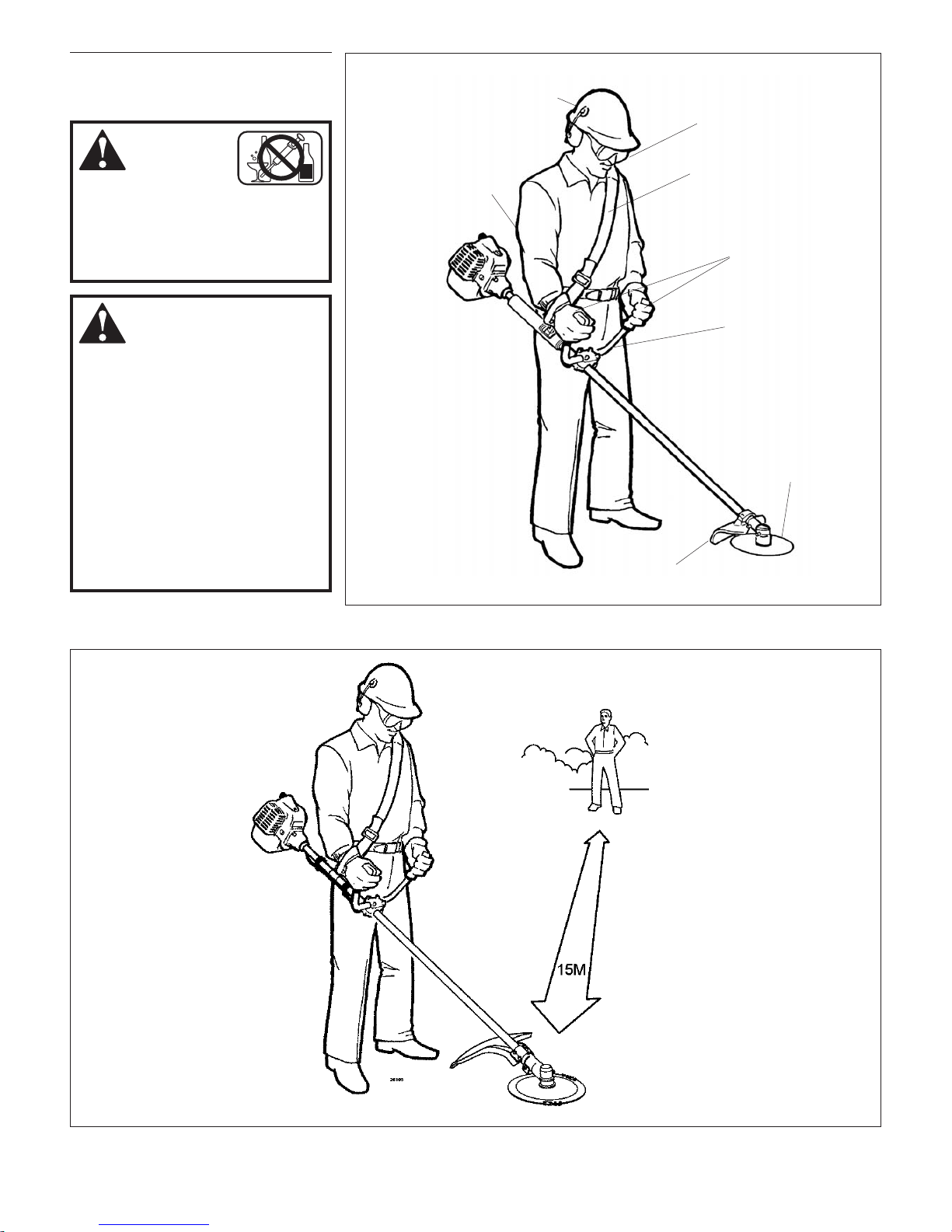
The Properly Equipped Operator
WARNING!
Minimize the Risk of Fire!
NEVER smoke or light res near the
trimmer or brushcutter.
ALWAYS stop the engine and let it
cool before refueling. Avoid overlling
and wipe off any fuel that may have
spilled.
ALWAYS move the unit to a place well
away from a fuel storage area or other
readily ammable materials before
starting the engine.
NEVER place ammable material
close to the engine mufer.
Stay Alert
You must be physically and mentally fit to
operate this unit safely.
WARNING!
Never operate power
equipment of any kind if you are tired
or if you are under the inuence of
alcohol, drugs, medication or any other
substance that could affect your ability
or judgement.
Safety Information
Always wear a strap
when operating a machine
equipped with a blade.
Wear close-tting clothing
to protect legs and arms.
Do not wear clothing or
jewelry that could get
caught in machinery or
underbrush. NEVER
wear shorts!
Wear hearing protection devices,
such as ear-mufers. wear a head
protection device, such as a helmet.
Secure long hair so that it is above
shoulder level.
Always wear eye protection
such as goggles or safety glasses
to shield against thrown objects.
When operating with a
blade, make sure the
handle is positioned to
provide you with maximum
protection from contacting
the blade.
Keep away from the rotating
trimmer line or blade at
all times, and never lift a
moving attachment above
waist-high.
Wear appropriate footwear
(non-skid boots or shoes): do
not wear open-toed shoes or
sandals. Never work bare-
footed!
Keep a proper footing
and do not overreach.
Maintain your balance at
all times during
operation.
Always make sure the appropriate cutting attachment
shield is correctly installed and in good condition.
Wear non-slip gloves. Always
operate with both hands rmly
gripping the unit.
Be Aware of the Working Environment
Avoid long-term
operation in very hot or
very cold weather.
Make sure bystanders
or observers outside the
15 meter “danger zone”
wear eye protection.
Be extremely careful of
slippery terrain, especially
during rainy weather.
Always make sure
the appropriate cutting
attachment shield is
correctly installed.
If contact is made with a hard
object, stop the engine and
inspect the cutting attachment
for damage.
Be constantly alert for objects and
debris that could be thrown either from
the rotating cutting attachment or
bounced from a hard surface.
Reduce the risk of bystanders
being struck by ying debris. Make
sure no one is within 15 meters
— that’s about 16 paces — of an
operating attachment.
Beware of a coasting blade when
brushcutting or edging. A coasting
blade can injure while it continues to
spin after the throttle trigger is released
or after the engine is stopped.
15
METERS
Always clear your work area of trash or
hidden debris that could be thrown back at
you or toward a bystander. When operating
in rocky terrain or near electric wires or fenc-
es, use extreme caution to avoid contacting
such items with the cutting attachment.
4
C220
T220
IMPORTANT!
Safety and Operation Information Labels: Make sure all information labels are
undamaged and readable. Immediately
replace damaged or missing information
labels. New labels are available from your
local authorized Shindaiwa dealer.
Safety Labels
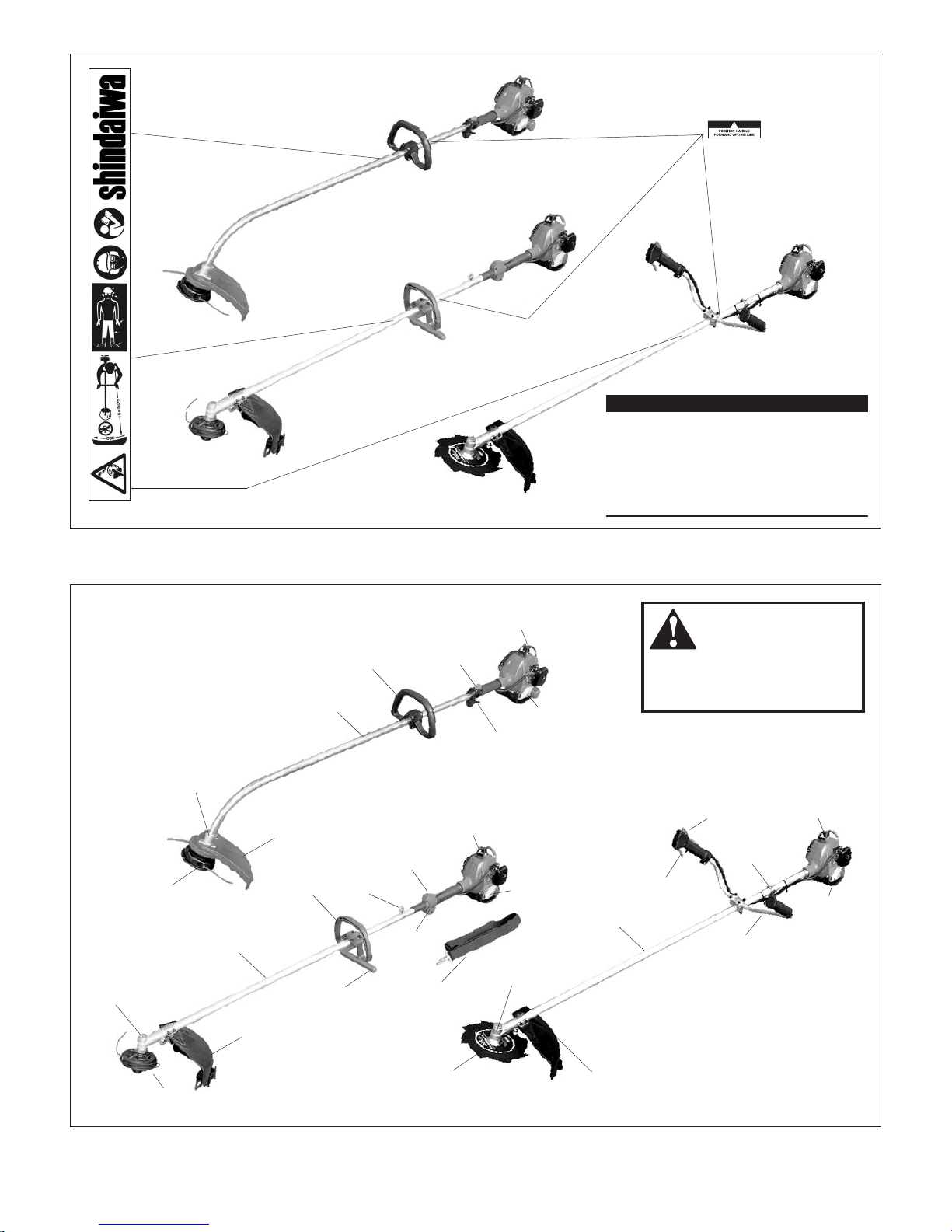
F220
F220 Grass Trimmer
Spark Plug
ON-OFF Switch
Throttle
Lever
Fuel Tank
Handle
Outer Tube
Gearcase
Cutting
Attachment
Shield
Trimmer
Head
Barrier Bar
T220 Grass Trimmer
Spark Plug
ON-OFF Switch
Throttle
Lever
Fuel Tank
Handle
Outer Tube
Gearcase
Cutting
Attachment
Shield
Trimmer
Head
Strap
Hanger
C220 Grass Trimmer
Spark Plug
ON-OFF Switch
Throttle
Lever
Fuel Tank
Handlebar
Outer Tube
Gearcase
Cutting
Attachment
Shield
8-Tooth
Blade
Hanger
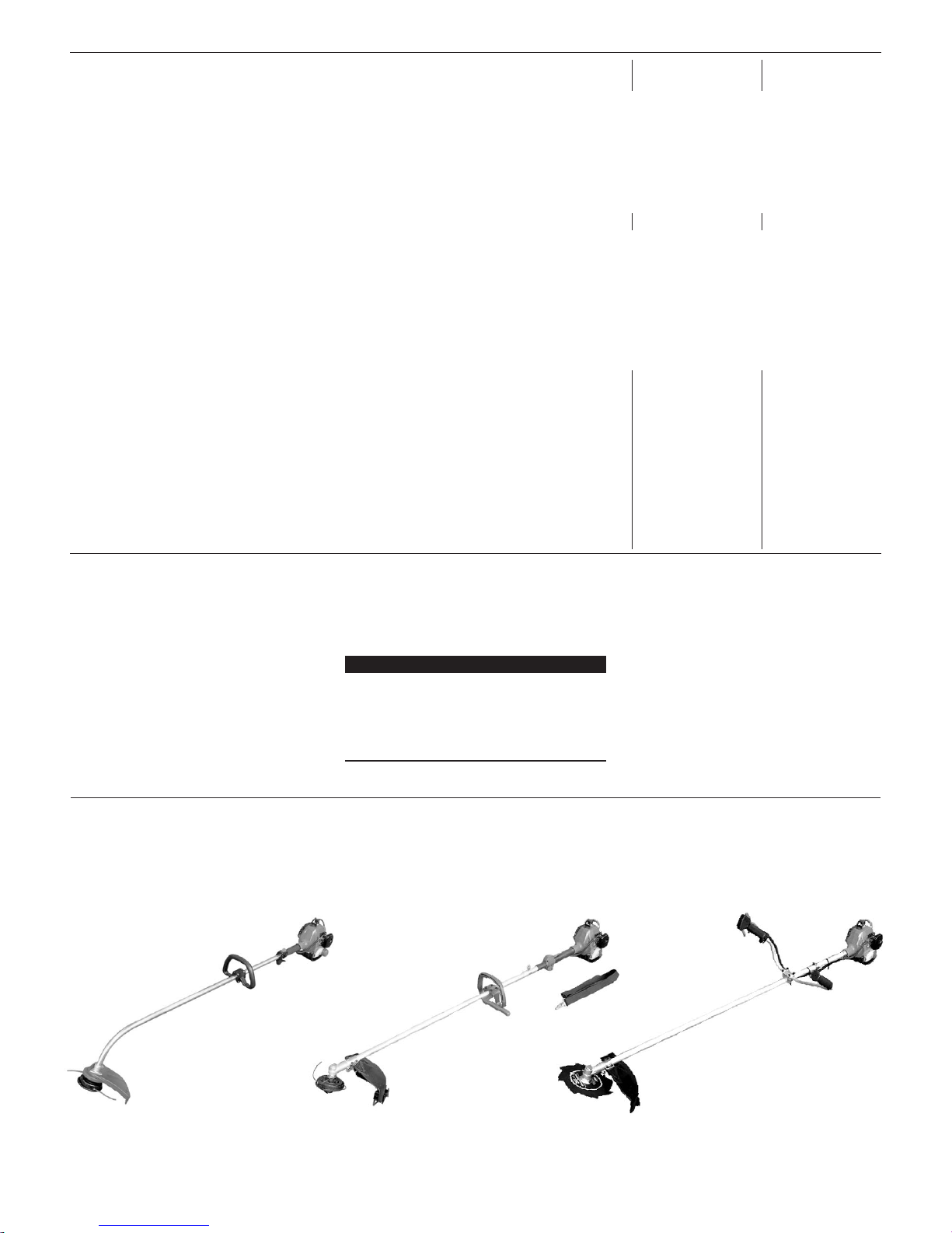
Using the accompanying illustrations as
a guide, familiarize yourself with your
machine and its various components.
Understanding your machine helps ensure top performance, long service life,
and safer operation.
Unit Description
WARNING!
Do not make unauthorized modi-
cations or alterations to any of
these units or their components.
5
* Sound Pressure Level: in accordance with EN ISO 11806 and ISO 7917
* Sound Power Level: in accordance with EN ISO 11806 and ISO 10884
* Vibration Level: in accordance with EN ISO 11806 and ISO 7916
note.1: 8-tooth blade equipped
note.2: Trimmer head equipped
Specications
Before assembling, make sure you have all
the components required for a complete
unit. This machine consists of the following components and accessories. Carefully
inspect all components for damage. If you
find any damaged or missing items, ask
your Shindaiwa dealer for support.
Prior to Assembly
Model Name ..............................................................................................
Engine Model ............................................................................................
Engine Type ..............................................................................................
Dry Weight
(excluding cutting attachment).....................................................
Bore x Stroke .............................................................................................
Displacement .............................................................................................
Engine Speed at Maximum Power Output .............................................
Maximum Power Output .........................................................................
Engine Speed at Idling .............................................................................
Maximum Engine Speed ..........................................................................
Fuel/Oil Ratio ............................................................................................
Fuel Tank Capacity ...................................................................................
Carburetor .................................................................................................
Ignition System .........................................................................................
Spark Plug ..................................................................................................
Air Cleaner .................................................................................................
Starting Method ........................................................................................
Stopping Method .......................................................................................
Handle ........................................................................................................
Dimensions (L x W x H = mm) ................................................................
Sound Pressure Level*, note.1
(average data between at Idling and at Racing)
.............
Sound Power Level *, note.1
(average data between at Idling and at Racing)
.................
Vibration Level*, note.1 .................................................Idling left/right
Vibration Level*, note.1 ...............................................Racing left/right
Sound Pressure Level *, note.2
(average data between at Idling and at WOT)
..............
Sound Power Level *, note.2
(average data between at Idling and at WOT
) ..................
Vibration Level*, note.2 .................................................Idling left/right
Vibration Level*, note 2 ................................................. WOT left/right
F220 T220 C220
n Engine Assembly (Powerhead) n Engine Assembly (Powerhead) n Engine Assembly (Powerhead)
n Outer Tube Assembly n Outer Tube Assembly n Outer Tube Assembly
n Debris Shield n Debris Shield n Debris Shield
n Front Handle (Loop Type) n Front Handle (Loop Type/Barrier Bar) n Front Handle (Bicycle Type)
n Tool Set n Tool Set n Tool Set
n Shoulder Strap n Shoulder Strap
IMPORTANT!
The terms “left,” “left-hand,” and “LH”,
“right,” “right-hand,” and “RH”; “front” and
“rear” refer to directions as viewed by the
operator during normal operation of this
product.
Specifications subject to change without notice.
F220/EC1 T220/EC1 C220/EC1
S220EC
2-cycle, vertical-cylinder, air-cooled
4.3 kg 4.4 kg 4.7 kg
31 mm x 28 mm
21.1 cm
3
7,500 RPM (min-1)
0.65 kW
2,900 RPM (min-1)
9,750 (min
-1
) 10,000 (min-1) 10,000 (min-1)
50:1
430 cm
3
Walbro WYL, Diaphragm
Fully Electronic, transistor controlled
NGK BMR6A
Foam Element
Recoil Starter
Slide Switch
Loop Type Loop Type Bicycle Type
1,555 x 255 x 435 1,690 x 365 x 335 1,715 x 605 x 450
n/a
91dB (A) 90dB (A)
n/a
102dB (A) 102 dB (A)
n/a
2.8/2.0 m/s2 1.6/2.0 m/s
2
n/a
6.1/7.3 m/s2 2.4/1.8 m/s
2
95dB (A) 95dB (A) 95dB (A)
105dB (A) 106dB (A) 106dB (A)
3.2/2.1 m/s
2
3.2/1.7 m/s2 1.4/2.2 m/s
2
6.8/9.6 m/s2 6.7/5.1 m/s2 4.2/4.6 m/s
2
6
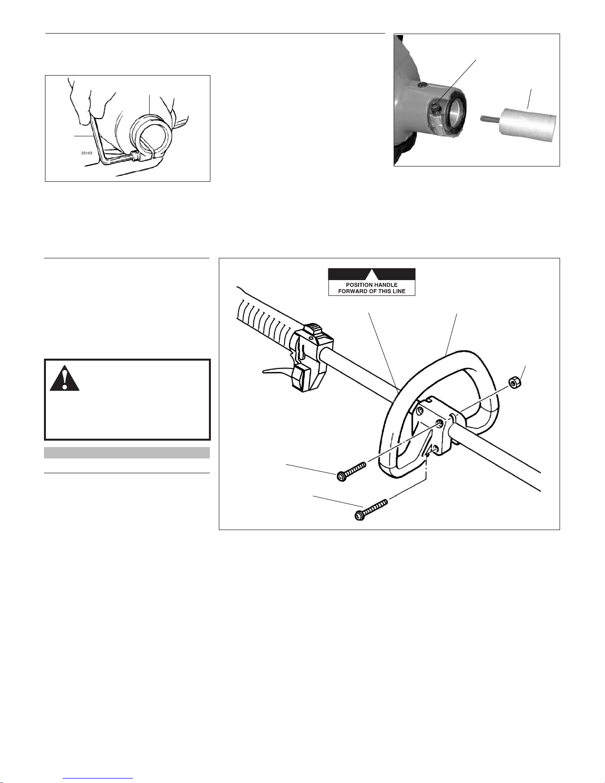
Handle F220
1. Position the front handle on the outer
pipe where the “Handle Label” is placed.
2. Press the handle on the outer pipe gen-
tly so that the handle stays as shown.
3. Tighten two 30 mm screws on upper
and two 45 mm screws on lower on the
handle with nuts.
Before Assembling the Outer Tube
1. Using the hex wrench, Loosen the joint
bolt.
Assembly of the Outer Tube
1. Slip the outer tube into the joint until
the tube bottoms. The outer tube or
gear case shaft may have to be rotated
slightly for the splines on the main shaft
to fully engage to the engine.
2. Tighten the joint bolt securely using the
hex wrench.
WARNING!
NEVER operate this machine without
the front handle. Operating without
the front handle may result in serious
injury.
NOTE:
The screws and nuts are packed in the tool bag.
Outer Tube
Joint Bolt
Outer Tube Assembly
Tube Clamp
Hex
Wrench
Assembly of the Handle
Front Handle
Nut
Screw(s) 30 mm
Screw(s) 45 mm
Handle Positioning Label
7
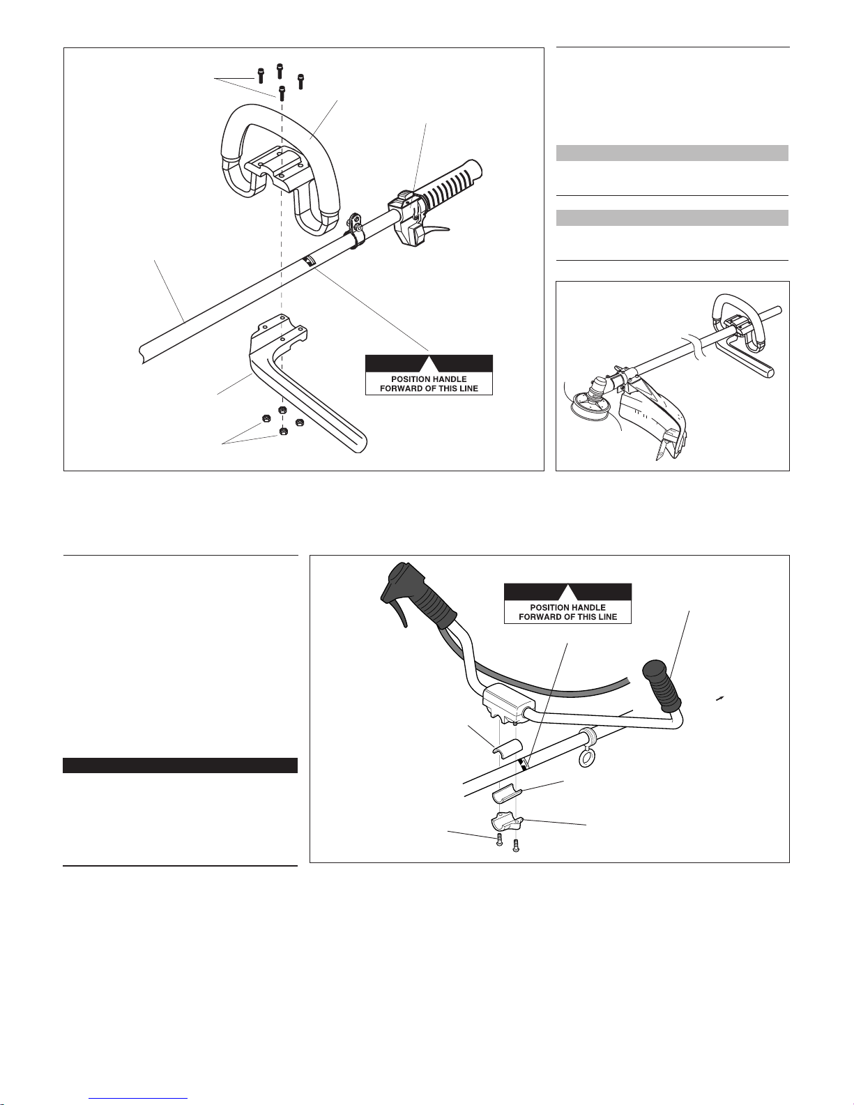
Handle T220
1. Put 4 square nuts in the frame of
barrier.
2. Fit the handle and barrier over the
outer tube and tighten four bolts.
NOTE:
Tighten four bolts in diagonal fashion for
protection of the handle.
NOTE:
Adjust the handle to the best position for
operator comfort.
26005
Outer Tube
Socket-head
Cap Screws
Handle
Barrier Bar
Throttle
Assembly
Nuts
Handle Positioning Label
Assembly of the Handle
Assembly of the Handle
27009B
Handlebar
Spacer
Spacer
Socket Head
Cap Screws
Lower Cap
Handle Positioning Label
Engine
Handlebar C220
1. Position the handle over the handle
label on the outer tube. Make sure the
throttle lever is on the right-hand side of
the outer tube.
2. Attach the handle mounting bracket
using the two socket-head cap screws,
washers, and lock washers. At this time,
ONLY finger tighten the screws.
3. Locate the handle about 5 inches ahead
of the shoulder strap hanger or at the
best position for operator comfort.
IMPORTANT!
Regardless of handlebar location, the
aluminum collar must remain in position
between the handlebar and the outer
tube. If the collar is omitted or is improperly installed, the handlebar bracket can
not be properly secured.
4. Using the hex wrench, securely tighten
the two handlebar cap screws.
5. Route the ribbed throttle cable tube
along the handlebar and outer tube.
Install the protector sleeve on the outer
tube.
8
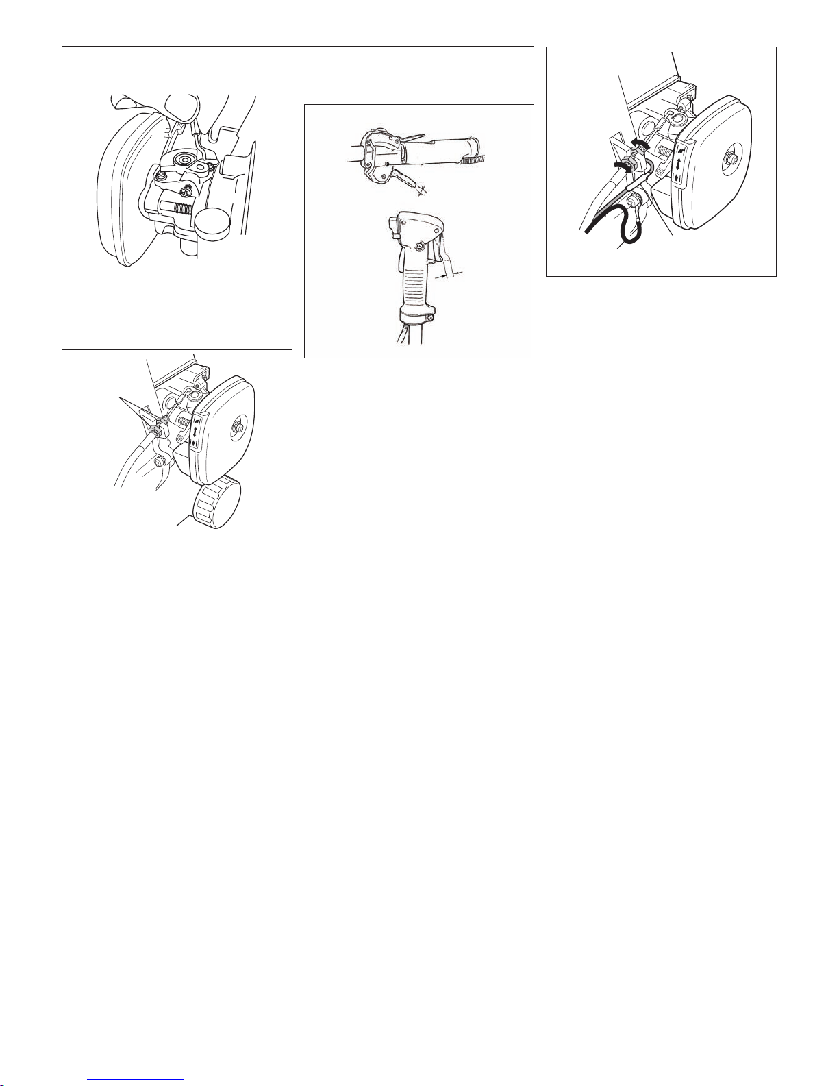
Throttle Cable Adjustment
1. Hook the end of the throttle cable to the
carburetor.
2. Place the throttle cable in the fan cover
slot and tighten (finger tight only) the
nuts so that the nuts are on either side
of the slot.
3. Adjust the nuts so that the free play of
trigger lever becomes 4~6 mm and then
tighten the nuts securely.
4. Fix the earth wire (black) to the fan
cover using the bolt below the fan cover
platform which holds the throttle cable.
5. Connect the switch and wire to the red
wire from the engine.
JAM NUTS
C220
Free Play
4 ~ 6 mm
Free Play
4 ~ 6 mm
Jam Nuts
F220/T220
(BLACK)
GROUND WIRE
(RED)
IGNITION WIRE
(Black)
Ground Wire
(Red)
Ignition Wire
9
F220
1. Place the cutting attachment shield
under the triangular flange.
2. Tighten 3 screws (16 mm).
NOTE:
The 3 screws (16 mm) are in the tool bag.
Cutting Attachment Shield Assembly
WARNING!
NEVER operate this machine without
the cutting attachment shield. Operating
without the cutting attachment shield may
result in serious injury.
WARNING!
Carefully inspect the cutting attachment
shield assembly to make sure it is tightened securely and does not wobble.
Flange
Cutting
Attachment
Shield
Screw 16 mm
WARNING!
The line cutter is very sharp. Wear
gloves to protect your hands when
handling.
To Change Position of Line Cutter.
1. Remove the 2 hex screws with a 4 mm
hex wrench.
2. Rotate line cutter.
3. Reinstall the two hex screws and tighten
them securely.
NOTE:
Be careful to not lose the 2 nuts in the cutting
attachment shield, they are not captured.
The line cutter can be positioned in
2 positions to obtain different line length
for cutting.
F220
Install the Cutting Attachment
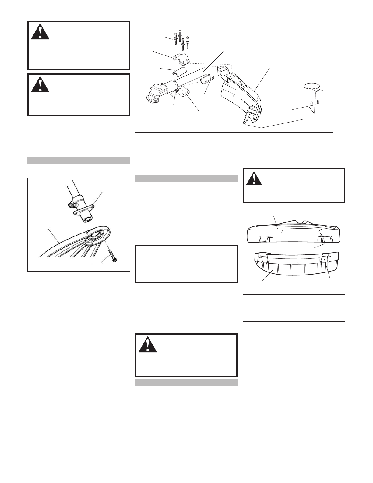
Shield C220/T220.
1. Insert the cutting attachment shield
between the outer tube and the cutting
attachment shield mounting plate.
CAUTION!
Make sure the clamp screw and retaining nut are securely tightened before
tightening the four socket-head cap
screws.
NOTE:
It may be necessary to loosen the retaining
nut and clamp screw to adjust cutting attachment shield mounting plate.
2. Fit the two shims and the bracket over
the outer tube and loosely install the
four socket-head cap screws.
3. Tighten the four socket-head cap screws
to secure the cutting attachment shield.
Sub-Shield.
(when trimmer head is in use)
1. Attach the shield extension to the
cutting attachment shield.
WARNING!
NEVER use this machine without subshield when using a trimmer head.
CAUTION!
Make sure the sub-shield is completely
hooked at the hook receiver.
Sub-shield
Hook
Hook
Receiver
Cutting Attachment Shield
Line Cutter
Hex
Screws
Socket-head
Cap Screws
Shim
Shim
Nut
Bracket
Cutting Attachment Shield
Outer Tube
T220/C220
Cutting Attachment
Shield Mounting
Plate

10
1031
C220
1. Turn the brushcutter over so that the
gearcase output shaft faces UP.
2. Remove the safety clip and slide holder
B onto the output shaft.
3. Rotate the tool holder and shaft until the
notch in the holder aligns with the notch
on the gearcase flange. Use the long
end of the hex wrench to lock the output
shaft in position.
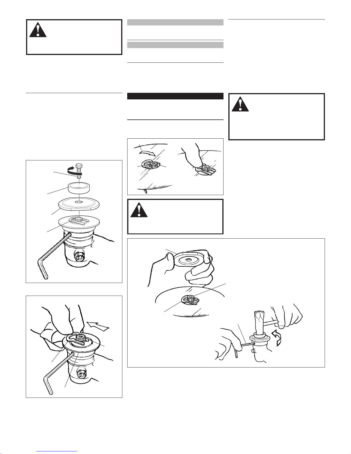
IMPORTANT!
The trimmer head has a left-hand thread.
Turn the trimmer head counter-clockwise
to install.
1. Make sure the switch is turned off and
the engine is stopped.
2. Turn the unit over so the shaft from the
gearcase faces up.
3. Install the collar to the gear-shaft and
place the holder onto the gear-shaft.
NOTE:
The collar and the holder are in the tool bag.
4. Rotate the holder until the hole in the
holder aligns with the notch on the
gearcase flange. Using the hex wrench,
lock the gearcase as shown.
5. While holding the holder with the hex
wrench, thread the trimmer head onto
the gear-shaft and install securely using
hand pressure.
a. F220
Turn clockwise to install.
Installing a Trimmer Head
b. T220/C220
Turn counter clockwise to install.
6. Remove the hex wrench.
4. While holding the hex wrench, thread
the trimmer head onto the output shaft,
turning counter-clockwise.
5. Using hand pressure only, tighten the
trimmer head firmly on the gear-shaft.
6. Remove the hex wrench.
F220/T220
Collar
Gearshaft
Holder
Notch
Arbor Bolt
Bolt Guard
Output
Shaft
Holder B
F220 C220/T220
Hex Wrench
Holder B
Output Shaft
Remove
Safety Clip
Holder A
Thread on the
trimmer head
Holder B
Holder A
11
1031
WARNING!
Never operate the F220 with a saw
blade. This may result in serious injury.
NOTE:
Consult with your Shindaiwa dealer for necessary items for blade-use. (T220)
NOTE:
The collar and the holder for trimmer head
use, are not to be used. (T220)
1. Turn the brushcutter upside down so
the gearcase output shaft is facing UP.
Align the hole in blade holder A with the
matching hole in the gearcase flange
and temporarily lock the output shaft by
inserting a hex wrench through both
holes.
2. Using the spark plug wrench, remove
the arbor bolt, bolt guard and holder B
from the gearcase shaft.
C220/T220 Cutting Attachment Installation and Assembly
3. Next, slide the safety clip off-center.
IMPORTANT!
Install the blade so its printed surface is
visible to the operator when the brushcutter is in the normal operating position.
4. Fit the blade over the safety clip and then
center it over the flange on holder A.
5. Lock the blade in place by centering the
safety clip on the output shaft.
6. Install blade holder B on the output
shaft. The recess in the holder must
completely cover the safety clip and
must fit tightly against the blade.
7. Install the bolt guard and then the blade
retaining bolt. Using the spark plug
wrench, tighten the bolt firmly in a counter-clockwise direction.
8. Remove the hex wrench.
WARNING!
The blade must t at against the
holder ange. The blade mounting hole
must be centered over the raised boss
on blade holder A.
WARNING!
Never operate the brushcutter without
the safety clip in place!
Mounting a Blade C220/T220
1. Make sure the switch is off and the
engine is stopped.
2. Wear gloves to protect your hands.
Arbor Bolt
Bolt Guard
Output
Shaft
Holder B
Slide the safety clip off-center
Safety
Clip
Holder A
Output
Shaft
Center the
safety clip
Safety
Clip
Blade
Slide the blade in place
Output
Shaft
Blade
Holder B
Install the blade holder
Output Shaft
Safety
Clip
Hex Wrench
(blade not
shown for
clarity)
Bolt Guard
Tighten the blade
holder assembly

12
Filling the Fuel Tank
IMPORTANT!
Mix only enough fuel for your immediate
needs! If fuel must be stored longer than
30 days and oil with fuel stabilizer
is not used, it should rst be treated with a
fuel stabilizer such as STA-BIL™.
Mixing Fuel
CAUTION!
This engine is designed to operate on
a 50:1 mixture consisting of unleaded
gasoline and 2-cycle mixing oil only.
Use of non-approved mixing oils can
lead to excessive carbon deposits.
CAUTION!
n Some types of gasoline contain al-
cohol as an oxygenate. Oxygenated
gasoline may cause increased operating temperatures. Under certain
conditions, alcohol-based gasoline
may also reduce the lubricating
qualities of some 2-cycle mixing oils.
n Never use any type of gasoline
containing more than 10% alcohol
by volume! Generic oils and some
outboard oils may not be intended
for use in high-performance 2-cycle
type engines, and should never be
used in your Shindaiwa engine.
n Use only fresh, clean unleaded gasoline
with a pump octane of 87 or higher.
n Mix with 50:1 Shindaiwa Premium
2-cycle mixing oil or with an equivalent
high quality 2-cycle mixing oil.
Examples of 50:1 mixing quantities
n 1 gallon of gasoline to 2.6 oz. mixing oil.
WARNING!
Minimize the Risk of re!
n STOP engine before refueling.
n ALWAYS allow the engine to cool
before refueling!
n Wipe all spilled fuel and move the
engine at least 3 meters from the
fueling point and source before
restarting!
n NEVER start or operate this
unit if there is a fuel leak.
n NEVER start or operate this
unit if the carburetor, fuel lines,
fuel tank and/or fuel tank cap are
damaged.
n NEVER smoke or light any res
near the engine or fuel source!
n NEVER place any ammable mate-
rial near the engine mufer!
n NEVER operate the engine without
the mufer and spark arrester in
good working condition.
1. Place the unit on a flat, level surface.
2. Clear any dirt or other debris from
around the fuel filler cap.
3. Remove the fuel cap, and fill the tank
with clean, fresh fuel.
4. Reinstall the fuel filler cap and tighten
firmly.
Gasoline 2-cycle mixing oil
Liters milliliters
2.5 l .............................. 50 ml
5 l ................................100 ml
10 l ..............................200 ml
20 l ..............................400 ml
13
WARNING!
MAKE SURE THE BLADE IS WELL
CLEAR OF ANY INTERFERENCE.
Before starting the engine, place unit
on clean, level surface. Make sure you
have good secure footing and always
keep a rm grip on the machine. THE
CUTTING ATTACHMENT MAY ROTATE WHEN THE ENGINE STARTS.
Starting the Engine
WARNING!
Move at least 3 meters away from the fuel
site before starting the engine.
WARNING!
Never operate the engine without the
cutting attachment installed.
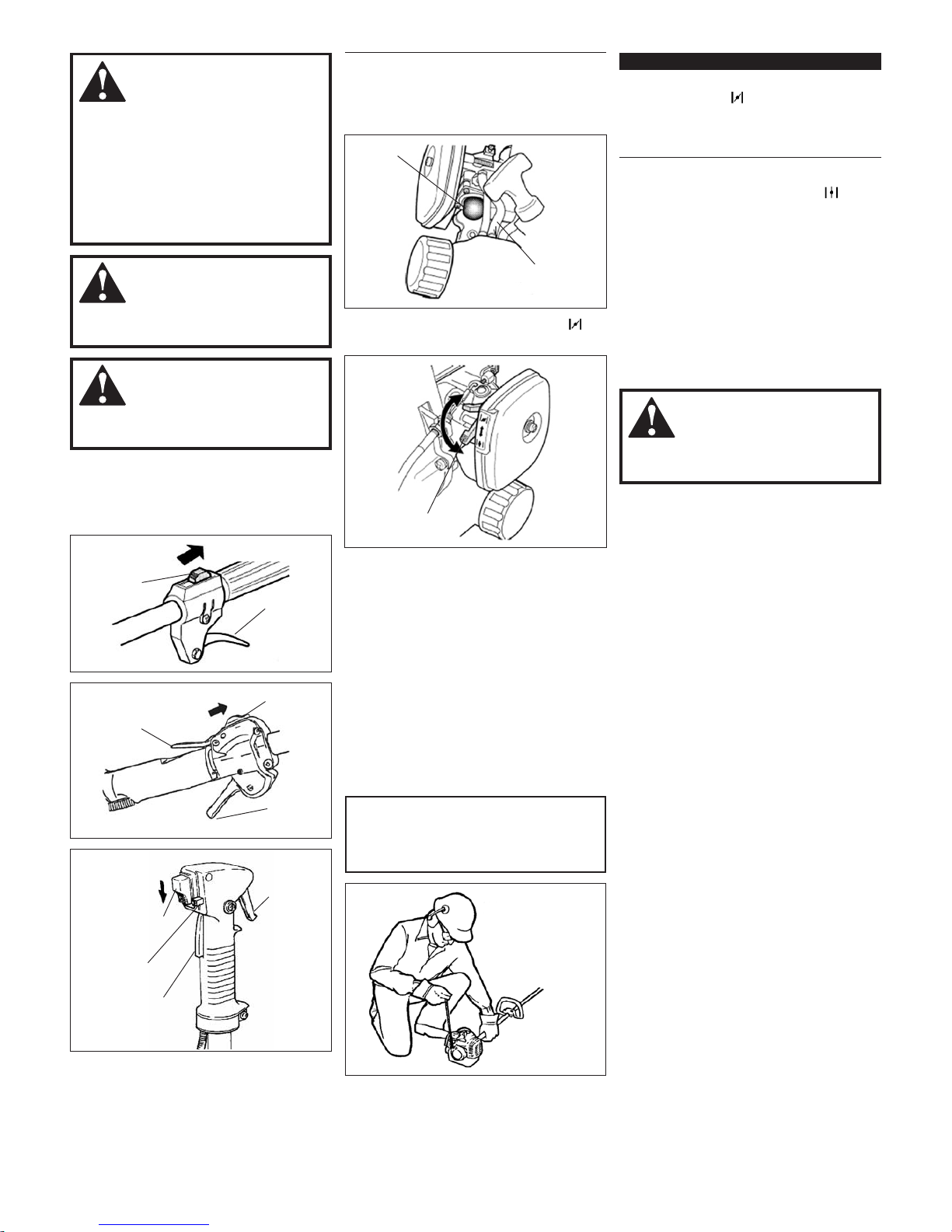
1. Starting a Cold Engine and/or
Restarting After Refueling.
a. Slide the ON-OFF switch to the “I”
position.
b. Prime the engine by repeatedly de-
pressing the carburetor primer bulb
until fuel can be seen flowing through
the transparent overflow return tube:
c. Push the choke lever upward (“
”
position).
d. (C220) Depressing the lock lever,
pull the throttle lever fully and depress the throttle lock button. While
depressing the throttle lock button,
release the throttle lever and the lock
lever. Now the throttle stays at high
idle (starting speed).
e. While firmly holding the outer tube
with one hand, pull the coil starter
handle upward with your other hand.
Pull slowly at first until you feel the
starter engage, then pull quickly
to start the engine. Do not pull the
starter rope to the end of its travel.
CAUTION!
Pulling the starter rope to the end
of its travel may damage the starter
mechanism.
IMPORTANT!
Repeated cranking of the engine with the
choke CLOSED (“
”) will lead to engine
ooding. If the engine fails to start after
several attempts, move the choke lever to
the OPEN position and continue cranking.
f. When the engine first fires, gradually
return the choke to OPEN (“
”) posi-
tion if you have not already done so.
n If the engine stops before the choke
is fully open, restart with the choke
closed.
n If the engine stops after the initial
firing, restart with choke closed.
g. (C220) When the engine starts and
is running, set the engine to idle by
tapping the throttle lever to release
the throttle lock.
WARNING!
Never start the engine from the operating position.
2. Starting a Warm Engine
Starting a warm engine involves all of the
steps of starting a cold engine.
EXCEPT:
n Do not press the primer bulb, and
n The choke should be in the OPEN
position.
If the engine does not start, follow the cold
engine starting procedure.
3. When the Engine Starts:
n After the engine starts, disengage
the throttle lock and allow the engine
to warm-up at idle for 2 or 3 minutes
before operating the machine.
n After the engine is warm, pick-up the
machine and clip on the strap.
n Advancing the throttle allows the
cutting attachment to rotate faster;
releasing the throttle allows the
attachment to stop. If the cutting
attachment continues to rotate, carburetor idle speed should be adjusted.
F220
ON-OFF
Switch
Throttle
Lever
T220
ON-OFF
Switch
C220
ON-OFF Switch
Lock
Lever
Throttle
Lever
Throttle
Lever
Lock
Lever
Throttle
Lock Button
Primer
Bulb
Overow
Return Pipe
Choke Lever
Make sure the
cutting head
is clear of
obstructions
14
WARNING!
The cutting attachment continues
moving for a while after the switch is
turned off.
1. Cool the engine by allowing it to idle for
2-3 minutes.
2. Move the ignition switch to the “O” or
STOP position.
Stopping the Engine
WARNING!
The cutting attachment should NEVER
rotate at engine idle.
The engine must return to idle speed
whenever the throttle lever is released.
Idle speed is adjustable, and must be set
low enough to permit the engine clutch
to disengage the cutting attachment
when the throttle is released.
Idle Speed Adjustment
WARNING!
When adjusting the engine, the cutting
attachment may rotate. Make sure the
cutting attachment is well clear of any
interference.
IMPORTANT!
Use a tachometer, if one is available, to
set engine idle. Standard idle speed is
2,900 (min
–1
) RPM.
Engine Idle Adjustment
WARNING!
A cutting attachment shield or other
protective device is no guarantee of
protection against ricochet. YOU MUST
ALWAYS GUARD AGAINST FLYING
DEBRIS!
WARNING!
NEVER use any cutting attachments
which are not recommended in this
manual. Using non-recommended cutting attachment may result in serious
injury.
WARNING!
When using a trimmer head, make
sure each of the line lengths are no
longer than 15 cm. Using a trimmer
head with lines longer than 15 cm
may damage the machine.
Unit Condition Check
NEVER operate the unit with the cutting attachment shield or other protection devices
(strap, blade retention clip, etc.) removed.
F220
ON-OFF
Switch
Throttle
Lever
T220
ON-OFF
Switch
C220
ON-OFF Switch
Lock
Lever
Throttle
Lever
Throttle
Lever
Lock
Lever
Throttle
Lock Button
To Increase
Idle Speed
To Decrease
Idle Speed
Idle Adjust
Screw
ALWAYS make sure the cutting attachment
fits properly into the appropriate cutter
holder. If a properly installed attachment
vibrates, replace the attachment with new
one and recheck.
ALWAYS stop the engine immediately and
check for damage if you strike a foreign
object or if the machine becomes tangled.
Do not operate with broken or damaged
equipment.
NEVER operate a machine with worn or
damaged fasteners or attachment holders.
NEVER cut with dull blades. Doing so will
increase the risk of blade thrust and may
also damage your equipment.
Use only authorized Shindaiwa parts and
accessories with this machine. Do not
make modifications to the machine without
the written approval of Shindaiwa.
ALWAYS make sure the cutting attachment
is properly installed and firmly tightened
before operation.
NEVER use a cracked or warped cutting attachment: replace it with a serviceable one.
1. Place unit on the ground, then start the
engine and allow it to idle for 2-3 minutes until warm.
2. If the attachment rotates when the
engine is at idle, reduce the idle speed
by turning the idle adjustment screw
counter-clockwise.
3. If the engine is stalling and won’t idle,
increase idle speed by turning the idle
adjustment screw clockwise
15
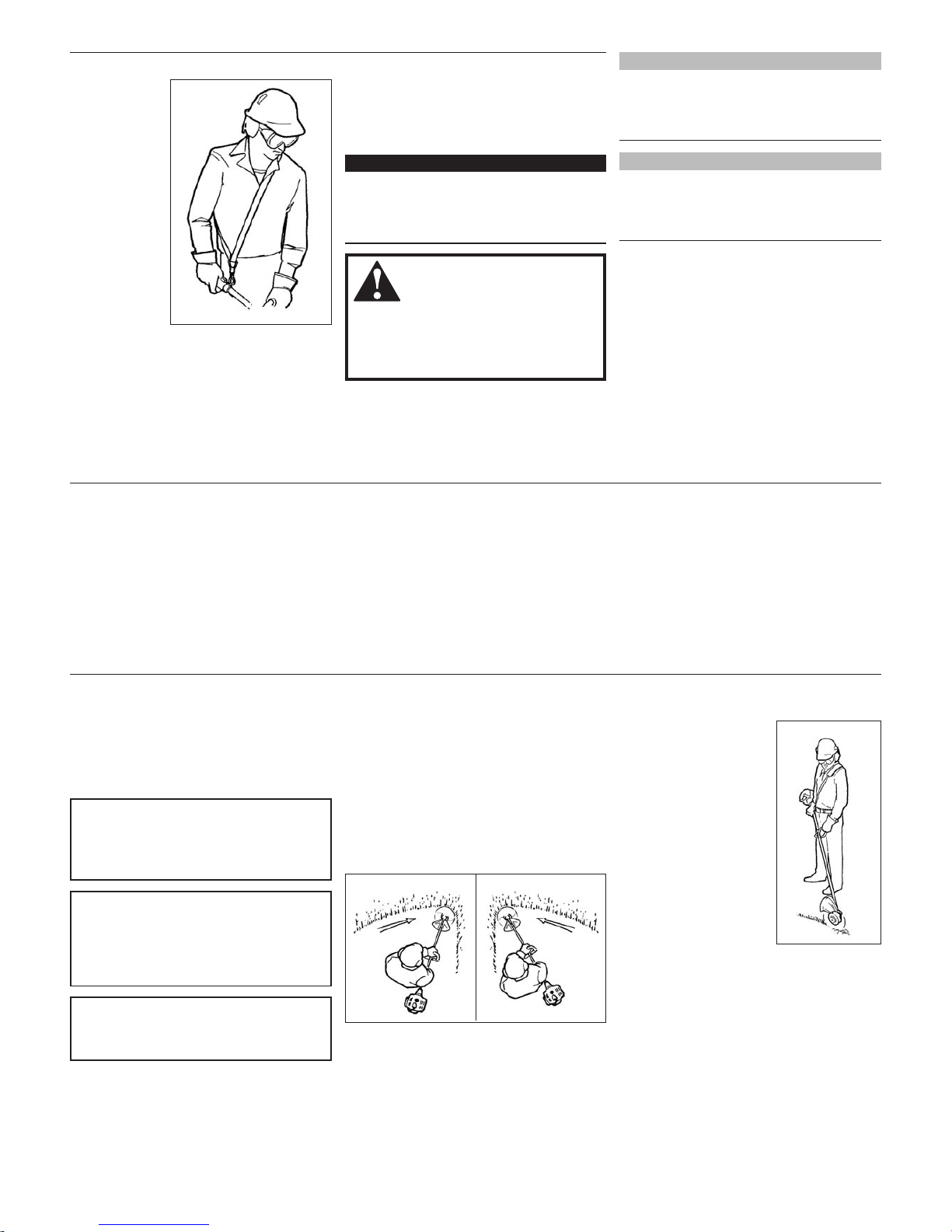
Edging
Tilt the handle approximately 100 degrees to the right (from
horizontal) and move forward while holding the
trimmer vertical.
Units Equipped with Trimmer Heads
Operation
Standard Shoulder Strap
Adjust the shoulder strap so the shoulder pad rests
comfortably
on the off-side
shoulder and
the cutting path
of the blade is
parallel to the
ground. Make
sure all hooks
and adjustment
devices are
secure.
Optional Brushcutter Harness
A harness provides additional protection
against blade thrust. In addition, a harness
gives significant support and comfort to
help ensure safe and efficient operation.
WARNING!
Always wear a shoulder strap when operating this unit with a blade. A shoulder strap is also recommended when
using trimmer line.
IMPORTANT!
When operating a brushcutter, make
sure both the handle and harness are
adjusted to the size of the operator using
the machine.
NOTE:
Although a shoulder strap accessory is not
required for use with a grass trimmer, a
shoulder strap can increase operator comfort
during extended periods of operation.
NOTE:
Using a shoulder strap when operating this
unit with a blade allows you to maintain
proper control of the unit and reduces fatigue
during extended operation.
Engine Operating Speeds
Operate the engine at full throttle while
cutting. Best fuel efficiency is obtained by
releasing the throttle when swinging back
after a cut.
n To prevent possible engine damage, do
not allow the trimmer or brushcutter to
run at high speeds without a load.
n Avoid operating the attachment at low
speeds. Doing so can lead to rapid
clutch wear. In addition, slow-speed operation tends to cause grass and debris
to wrap around the cutting attachment.
CAUTION!
Operation of trimmer without a cutting
attachment shield and using excessive
line length can lead to premature clutch
failure.
Your Shindaiwa F220/T220/C220 grass
trimmer is equipped with a semiautomatic
nylon trimmer head.
Trimming and Mowing Grass
CAUTION!
Do not push the rotating line into trees,
wire fences or any material that could
tangle or break the nylon lines.
Engine Operating Speeds
Operate the unit at full throttle while cutting grass.
CAUTION!
Operation at low RPM can lead to premature clutch failure.
Hold the grass trimmer as shown in the
illustrations. The trimmer head should
be angled slightly into the area to be cut.
To ensure maximum trimmer-line service
life, cut only with the tip of the trimmer
line. Sweep the trimmer head left to right
(T220/C220), and right to left (F220) to
trim the grass. During cutting operations,
the trimmer head should be kept horizontal
to the ground at all times.
T220/C220 F220

16
Using a Blade
WARNING!
n Before working with a blade-
equipped unit, always inspect and
clean the area of objects that could
interfere with or damage the blade.
n Never use a blade near sidewalks,
fence posts, buildings or other
objects that could cause injury or
damage.
n Never use a blade for purposes
other than those for which it was
designed.
n Whenever you strike a hard ob-
ject with a blade, always stop the
brushcutter and carefully inspect the
blade for damage. NEVER OPERATE THE BRUSHCUTTER WITH A
DAMAGED BLADE!
n A blade-equipped unit must be
equipped with a bicycle-type handlebar or barrier bar as well as a harness or shoulder strap.
n Always make sure the cutting at-
tachment shield is properly installed
before operating this unit.
Blade Thrust
‘Blade thrust’ is a sudden sideways or
backward motion of the brushcutter. Such
motion may occur when the blade jams or
catches on an object such as a sapling tree
or tree stump. BE CONSTANTLY ALERT
FOR BLADE THRUST AND GUARD
AGAINST ITS EFFECTS!
Brushcutter Handlebar
A brushcutter handlebar or barrier bar
helps prevent the operator from moving
forward, or the unit moving rearward, thus
preventing inadvertent bodily contact with
the blade. ALWAYS KEEP THE HANDLEBAR OR BARRIER BAR SECURELY IN
PLACE ON THE UNIT!
Make sure to use the following recommended Shindaiwa cutting attachment with
this machine.
(A) T220, C220
PART NUMBER 67000-65010
UN-34-7L
TAP & FEED TRIMMER HEAD
BOLT DIAMETER: 7 mm
THREAD: LEFT, 1.0 mm PITCH
Recommended Cutting Attachment
The blade rotates counter-clockwise. For
best performance and to minimize being
stuck by debris, move the blade from right
to left while advancing on your work.
C220/T220
Position the blade so cuts are made between the blade’s 8 o’clock and 10 o’clock
positions (as viewed from above). DO NOT
cut between the 10 o’clock and 5 o’clock
positions.
WARNING!
When cutting wood with a saw, feed the
blade slowly—never strike or “slam” a
spinning blade against the wood.
WARNING!
DO NOT use 2-tooth or non-Shindaiwa
approved 4-tooth cutting blades with
Shindaiwa trimmers and brushcutters.
Vertical Cuts
Hold the brushcutter with the blade at a 900
angle to the ground so the blade’s bottom
edge rotates toward the operator. Move the
blade from top to bottom through the cut,
and cut only with the bottom edge of the
blade.
WARNING!
When making vertical cuts, never allow
the blade to exceed waist height.
Cut on the left side of
the blade. KEEP YOUR
BODY OUTSIDE
THE PATH OF BLADE
ROTATION
D
O
N
O
T
C
U
T
Ten
O'clock
OK To Cut
Eight
O'clock
Five
O'clock
Blade
Rotation
C220/T220
Brushcutter Shoulder Strap
A shoulder strap provides additional
protection against blade thrust. In addition,
a shoulder strap gives significant support
and comfort to help ensure safe and
efficient operation.
When operating a unit with a blade, make
sure both the handle and shoulder strap
are adjusted to the size of the operator using the unit.
PART NUMBER 60903-98320
4-TOOTH BLADE
INNER BORE: 25.4 mm
DIAMETER: 255.0 mm
THICKNESS: 2.0 mm
PART NUMBER 60903-98310
8-TOOTH BLADE
INNER BORE: 25.4 mm
DIAMETER: 255.0 mm
THICKNESS: 2.0 mm
(B) F220
PART NUMBER 67001-65010
TAP & FEED TRIMMER HEAD
BOLT DIAMETER: 8 mm
THREAD: RIGHT, 1.25 mm PITCH
17
Prior to each work day, perform the
following:
n Remove the dirt and debris from the
engine, check the cooling fins and air
cleaner for clogging, and clean them as
necessary.
Daily Maintenance
10 Hour Maintenance
CAUTION!
Do not operate the machine if the air
cleaner or element is damaged, or if
the element is wet.
Every 10 hours of operation (more
frequently in dusty or dirty conditions):
n Remove the air cleaner element from the
carburetor and clean it thoroughly with
soap and water. Let dry before reinstalling the element.
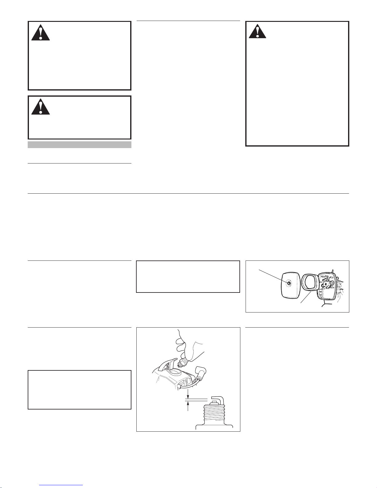
10/15 Hour Maintenance
CAUTION!
Before removing the spark plug, clean
the area around the plug to prevent dirt
and dust from getting into the engine’s
internal parts.
Every 10 to 15 hours of operation:
Remove and clean the spark plug.
n Adjust the spark plug electrode gap to
0.6 mm. If the plug must be replaced,
use only a NGK BMR6A.
Maintenance
WARNING!
Non-standard parts may not operate
properly with your unit and may cause
damage and lead to personal injury.
Mufer
This unit must never be operated with a
faulty or missing spark arrester or muffler. Make sure the muffler is well secured
and in good condition. A worn or damaged
muffler is a fire hazard and may also cause
hearing loss.
Spark Plug
Keep the spark plug and wire connections
tight and clean.
Fasteners
Make sure nuts, bolts, and screws (except
carburetor adjusting screws) are tight.
WARNING!
n Never repair a damaged blade by
welding, straightening, or by modifying its shape. An altered blade may
break during operation, resulting in
serious personal injury.
n DO NOT use 2-tooth or non-
Shindaiwa approved 4-tooth cutting
blades on Shindaiwa trimmers or
brushcutters.
n Blades are not interchangeable
between Shindaiwa edgers and trimmer/brushcutter models. Operating
any unit with a blade or attachment
not approved for that unit can be
hazardous and may cause serious
injury.
WARNING!
Before performing any maintenance,
repair, or cleaning work on your unit,
make sure the engine and cutting
attachment are completely stopped.
Disconnect the spark plug wire before
performing service or maintenance
work.
NOTE:
Using non-standard replacement parts could
invalidate your Shindaiwa warranty.
Blades
Keep blades sharp and check blade
condition frequently. If a blade’s performance changes suddenly, stop the engine
and check the blade for cracks or other
damage. Replace a damaged blade
IMMEDIATELY!
n Carefully remove any accumulations
of dirt or debris from the muffler and
fuel tank. Dirt buildup in these areas
can lead to engine overheating, fire, or
premature wear.
n Check for loose or missing screws or
components. Make sure the cutting attachment is securely fastened.
n Check the machine for leaking fuel or
grease.
Loosen the screw
Remove and clean the element
Clean the spark
plug and check
the gap at the
electrode.
0.6 mm
18
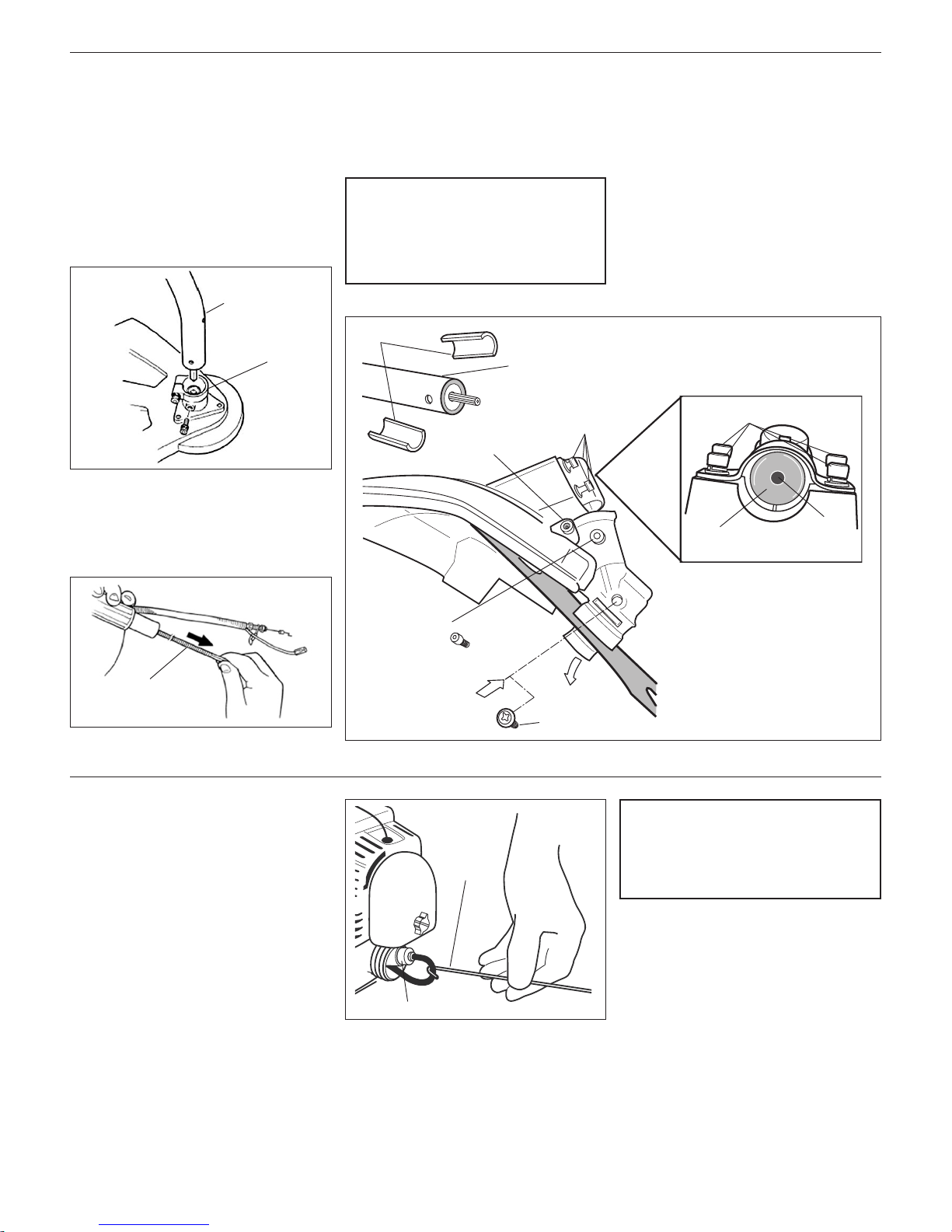
50 Hour Maintenance
T220/C220
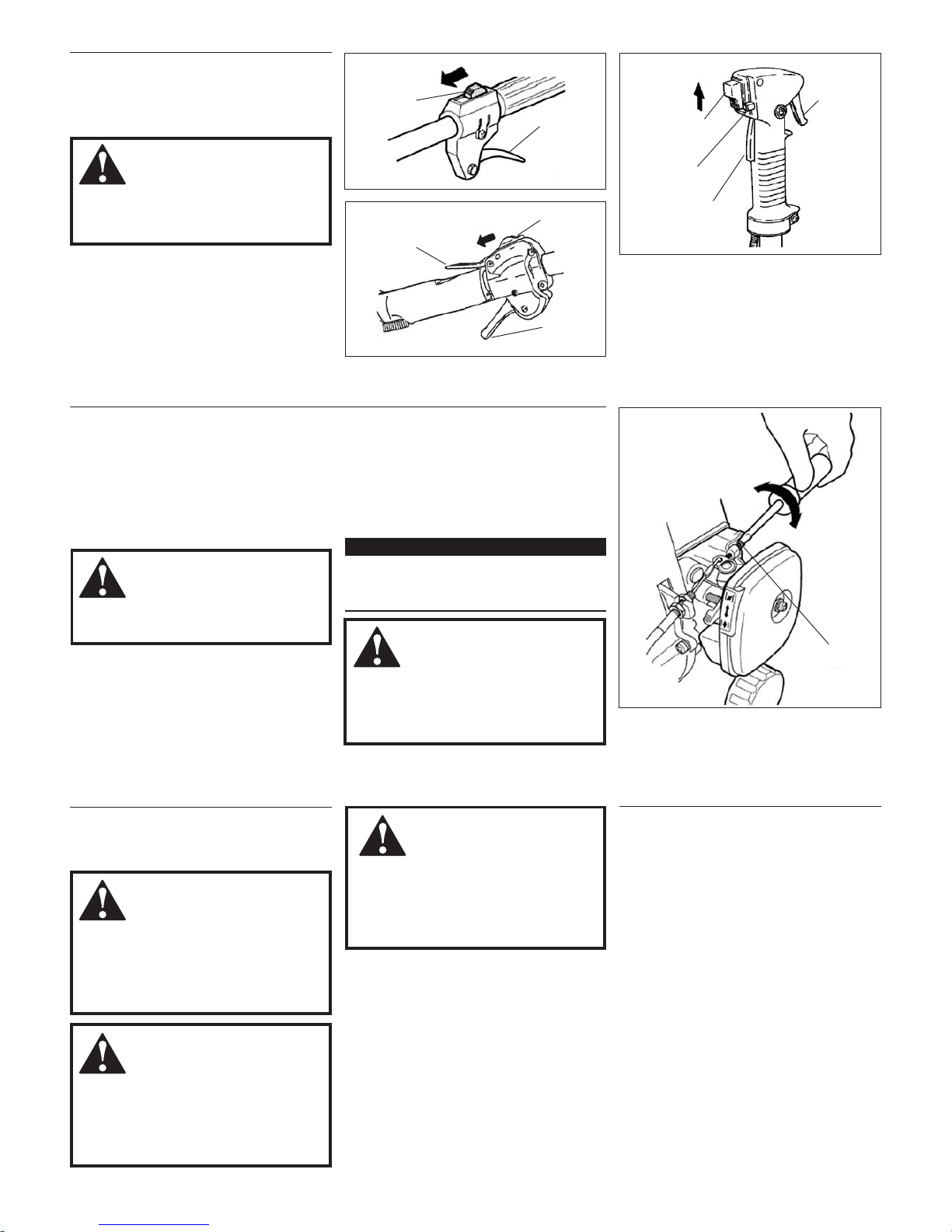
1. To perform this operation, first remove
the gearcase and debris shield from the
outer tube as follows.
n Remove the index bolt from the
gearcase.
CAUTION!
Do not remove the D-shaped shim
washer! The shim washer prevents
damage from overtightening the tube
clamp screw.
F220
Apply new grease to the flexible shaft.
1. Disassemble the shaft case from the
outer tube.
2. Disconnect the throttle wire and the
other wires, and disassemble the outer
pipe from the engine.
3. Take the flexible shaft out and apply new
grease evenly on the shaft.
4. Reassemble.
Gearcase Lubrication
Outer Tube
Shaft Case
Flexible Shaft
Every 50 hours of operation (more
frequently in dusty or dirty conditions):
n Remove and clean the cylinder cover
and clean grass and dirt from the cylinder fins.
Shims
Outer Tube
Clamp Screw
4 Socket
Head Screws
Index Bolt
New
Grease
Grease Plug
Old
Grease
4 Socket
Head Screws
Outer Tube
Cavity
Old
Grease
n Use a hooked wire to extract the fuel
filter from inside the fuel tank. Inspect
the fuel filter element for signs of
contamination. If it shows signs of contamination from debris, replace it with
a genuine Shindaiwa replacement fuel
filter element. Before reinstalling the filter, inspect the fuel line. If you discover
damage or deterioration, the unit should
be removed from service until it can be
inspected by a Shindaiwa-trained service
technician.
CAUTION!
Make sure you do not pierce the fuel
line with the end of the hooked wire.
The line is delicate and can be damaged easily.
Fuel Filter Maintenance
Hooked
Wire
n Loosen the gearcase clamp screw.
n Loosen the four socket head cap screws
that secure the cutting attachment
shield.
n Slide the gearcase and cutting attach-
ment shield off the tube. (Do not lose
the two shims).
2. Remove the filler plug and press new
grease into the gearcase until old grease
is purged from the gearcase, which can
be seen in the outer tube cavity.
3. Clean up the excess grease and reinstall
the cutting attachment shield, two shims
and the gearcase.
Filter Element
19
4-Tooth Blade 8-Tooth Blade
Mufer Maintenance
Hard starting or a gradual loss of performance can be caused by carbon deposits
lodged in the muffler’s spark arrester
screen.
n In such cases, performance can usu-
ally be restored by removing the spark
arrester screen and giving it a thorough
cleaning with a stiff bristle brush.
n If carbon deposits are severe or if no
performance improvement is noted,
your unit should be returned to your
Shindaiwa dealer for inspection.
WARNING!
Never operate this unit with a damaged
or missing mufer or spark arrester!
Operating with missing or damaged ex-
haust components is a re hazard and
may also damage your hearing.
n Remove the spark plug and pour about
7 grams of oil into the cylinder through
the spark plug hole. Slowly pull the recoil starter 2 or 3 times so oil will evenly
coat the interior of the engine. Reinstall
the spark plug.
Whenever the machine will not be
used for 30 days or longer, use the fol-
lowing procedures to prepare it for storage.
n Clean external parts thoroughly and
apply a light coating of oil to all metal
surfaces.
n Drain all the fuel from the carburetor
and the fuel tank.
IMPORTANT!
All stored fuels should be stabilized with a
fuel stabilizer such as STA-BIL™.
CAUTION!
Gasoline stored in the carburetor for a
long time will likely cause hard starting
and could lead to increased service
and maintenance costs.
Long Term Storage
Spark
Arrester
Mufer
n Before storing the machine, repair or
replace any worn or damaged parts.
n Remove the air cleaner element from
the carburetor and clean it thoroughly
with mixed fuel. Squeeze out the fuel
and reassemble the element.
n Store the machine in a clean, dust free
area.
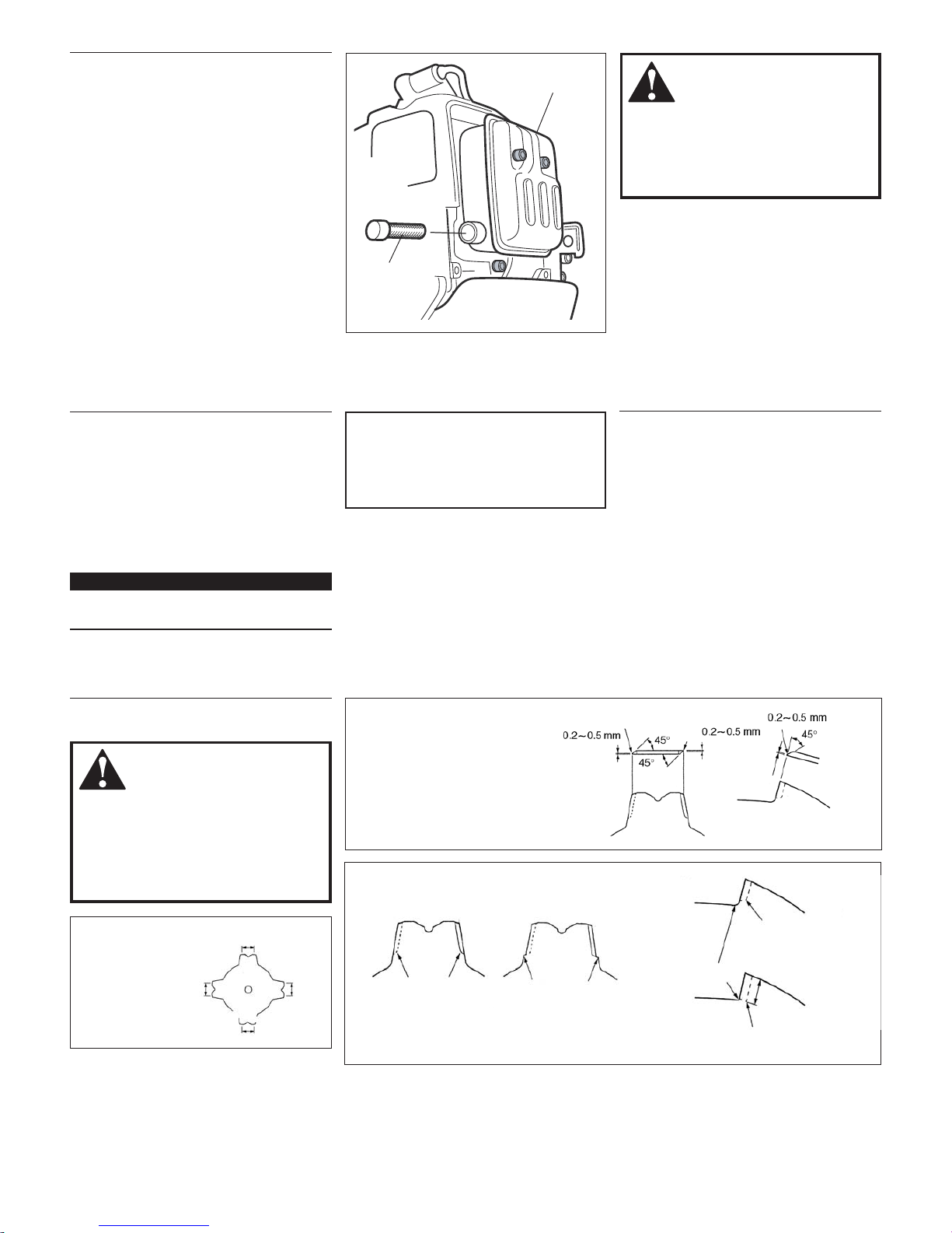
Blade Sharpening
WARNING!
Sharpen only the cutting teeth of a
blade. DO NOT alter the contour of the
blade in any way. In order to keep the
blade in balance, all cutting edges must
be sharpened equally. DO NOT le the
tips of the teeth too sharp.
With the file or a grinder, file a blade as
follows.
Make sure the width
of the 4 sides
are all the same.
The sharpening angle should
be approximately 45°.
Do not le the tips of the blade
too sharp. leave 0.2 ~ 0.5 mm
unsharpened.
The bottom of each tooth must remain
unsharpened. (Blade as viewed from bottom.)
4-Tooth Blade
8-Tooth Blade

20
NO
Troubleshooting Guide
Does the engine crank?
Good compression?
Does the tank contain fresh fuel
of the proper grade?
Is fuel visible and moving in the
return line when priming?
Is there spark at the spark plug
wire terminal?
Check the spark plug.
Faulty recoil starter.
Fluid in the crankcase.
Internal damage.
Loose spark plug.
Excess wear on cylinder, piston, rings.
Fuel incorrect, stale, or contaminated;
mixture incorrect.
Check for clogged fuel filter and/or vent.
The ignition switch is in the STOP position (OFF).
Shorted ignition wires.
Faulty ignition module.
If the plug is wet, excess fuel may
be in the cylinder.
The plug is fouled or improperly gapped.
The plug is damaged internally or
of the wrong size.
Consult with an authorized servicing dealer.
Tighten and re-test.
Consult with an authorized servicing dealer.
Refill with clean fresh unleaded gasoline with
a pump octane of 87 or higher, mixed with
Shindaiwa Premium 2-cycle mixing oil at a 50:1
gasoline/oil ratio.
Replace fuel filter or vent as required. Restart.
Move switch to START (ON) position and restart.
Consult with an authorized servicing dealer.
Crank the engine with the plug removed, replace the
plug, and restart.
Clean and regap the plug to 0.6 ~ 0.7 mm.
Restart.
Replace the plug with a NGK BPMR6A.
NO
YES
What To Check Possible Cause Remedy
ENGINE DOES NOT START
NO
YES
NO
YES
YES
NO
YES
Is the engine overheating?
Engine is rough at all speeds.
May also have black smoke and/
or unburned fuel at the exhaust.
Operator is overworking the unit.
Carburetor mixture is too lean.
Improper fuel/oil ratio.
Fan, fan cover, cylinder fins dirty or damaged.
Carbon deposits on the piston or in the muffler.
Clogged air filter.
Loose or damaged spark plug.
Air leakage or clogged fuel line.
Water in the fuel.
Piston seizure.
Faulty carburetor and/or diaphragm.
Overheating condition.
Improper fuel.
Carbon deposits in the combustion chamber.
Shorten trimmer line. Cut at a slower rate.
Consult with an authorized servicing dealer.
Refill with clean fresh unleaded gasoline with
a pump octane of 87 or higher, mixed with
Shindaiwa Premium 2-cycle mixing oil at a 50:1
gasoline/oil ratio.
Clean, repair or replace as necessary.
Consult with an authorized servicing dealer.
Service the filter.
Tighten or replace.
Repair or replace filter and/or fuel line.
Replace the fuel.
Consult with an authorized servicing dealer.
See above.
Check fuel octane rating; check for presence of
alcohol in the fuel. Refuel as necessary. See page 12.
Consult with an authorized servicing dealer.
What To Check Possible Cause Remedy
LOW POWER OUTPUT
Engine is knocking.
 Loading...