

Shindaiwa F220, T220, C220 Owner's/operator's Manual

F220
Part Number 62090-94310 Rev. 10/04
WARNING!
Read this manual and familiarize yourself with its contents.
This machine is designed for cutting grass, weed, and bushes. Do
not use this machine for other purposes.
Minimize the risk of injury to yourself and others.
Do not operate or service this machine unless you clearly
understand this manual.
Keep this manual at a particular place so that you can reread it
whenever you have a question about its use.
SHINDAIWA OWNER’S/OPERATOR'S MANUAL
F220 GRASS TRIMMER
T220 GRASS TRIMMER
C220 BRUSHCUTTER
T220
C220
2
1 Attention Statements ...................... 2
2 Warning Labels .............................. 2
2-1 The Properly Equipped Operator ..... 3
2-2 General Safety Instructions ............. 4
2-3 Working Environment Warning ........ 4
3 Product Description ........................ 5
4 Technical Specifications ................. 6
5 Assembly Procedure ...................... 6
5-1 Prior to Assembly ........................ 6
5-2 Before assembling Outer Tube ...7
5-3 Assembly of the Outer Tube.......... 7
5-4 Assembly of the Handle................. 7
5-5 Adjustment of the Throttle Cable... 8
5-6 Cutting Attachment Shield Assembly .. 9
5-7 Trimmer Head Installation ............. 9
5-8 Mounting a Blade ........................ 10
6 Starting - Stopping -
Adjusting the Engine .................... 11
6-1 Filling the Fuel Tank .................... 11
6-2 Starting the Engine ...................... 11
6-3 Stopping the Engine .................... 12
6-4 Engine Idle Adjustment ................ 12
7 Unit Condition Check ...................... 13
8 Operation ........................................ 13
8-1 Engine Operating Speeds ........... 13
8-2 Standard Shoulder Strap ............. 13
8-3 Units equipped with trimmer heads
....................................................... 14
9 Blades ............................................. 14
9-1 Using a Blade .............................. 14
10 Recommended Cutting
Attachments .............................. 15
11 Maintenance ................................. 16
11-1 Daily Maintenance ..................... 16
11-2 10-Hour Maintenance ................ 16
11-3 10/15-Hour Maintenance ........... 16
11-4 50-Hour Maintenance ................ 16
11-5 Gearcase Lubrication ................ 17
11-6 Fuel Filter Maintenance ............. 18
11-7 Muffler Maintenance .................. 18
11-8 Long Term Storage .................... 18
12 Blade Sharpening ......................... 19
13 Troubleshooting Guide ................. 19
14
Declaration of Conformity ..................... 22
Contents
Throughout this manual are special
“attention statements” surrounded
by boxes and preceded by the triangular Attention Symbol.
1 Attention Statements
WARNING!
A statement preceded by the
triangular attention symbol and
the word “WARNING” contains information that should be acted
upon to prevent serious bodily injury.
CAUTION!
A statement preceded by the word
“CAUTION” contains information that
should be acted upon to prevent mechanical damage.
IMPORTANT!
A statement preceded by the word
“IMPORTANT” is one that possesses
special significance.
NOTE:
A statement preceded by the word
“NOTE” contains information that is
handy to know and may make your job
easier.
2 Warning Labels
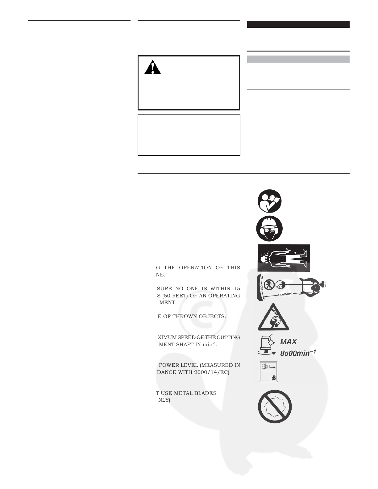
Warning labels affixed to the
machine are as follows:
READ AND FOLLOW THE OPERATOR’S
MANUAL. FAILURE TO DO SO COULD
RESULT IN SERIOUS INJURY.
WEAR HEAD, EYE AND HEARING
PROTECTION DURING THE OPERATION
OF THIS MACHINE.
WEAR NONSLIP GLOVES, LONG
TROUSERS AND NONSKID BOOTS
DURING THE OPERATION OF THIS
MACHINE.
MAKE SURE NO ONE IS WITHIN 15
METERS (50 FEET) OF AN OPERATING
ATTACHMENT.
BEWARE OF THROWN OBJECTS.
THE MAXIMUM SPEED OF THE
CUTTING
ATTACHMENT SHAFT IN
min-1.
SOUND POWER LEVEL (MEASURED IN
ACCORDANCE WITH 2000/14/EC)
DO NOT USE METAL BLADES
(F220 ONLY)
PAGE
3
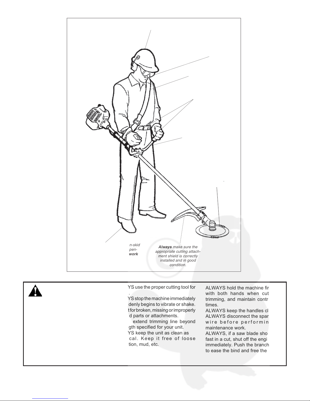
2-1 The Properly Equipped Operator
Always wear a harness
when operating a unit
equipped with a blade.
Always operate with
both hands firmly
gripping the unit.
Wear close-fitting clothing to
protect legs and arms. Gloves
offer added protection and are
strongly recommended. Do not
wear clothing or jewelry that
could get caught in machinery
or underbrush. Secure long
hair so that it is above
shoulder level.
NEVER wear shorts!
Wear hearing protection devices and a
broad-brimmed hat or helmet.
When operating with a blade,
make sure the handle is posi-
tioned to provide you with
maximum protection from
contacting the blade.
Keep away from the rotating
trimmer line or blade at all
times, and never lift a moving
attachment above waist-high.
Wear appropriate footwear (non-skid
boots or shoes): do not wear open-
toed shoes or sandals. Never work
barefooted!
Keep a proper
footing and do not
overreach.
Maintain your
balance at all times
during operation.
Always make sure the
appropriate cutting attach-
ment shield is correctly
installed and in good
condition.
WARNING!
Use Good Judgment
ALWAYS wear eye
protection to shield against thrown
objects.
NEVER run the engine when
transporting the machine.
NEVER run the engine indoors - make
sure there is always good ventilation.
Fumes from engine exhaust can cause
serious injury or death.
ALWAYS clear your work area of trash
or hidden debris that could be thrown
back at you or toward a bystander.
ALWAYS use the proper cutting tool for
the job.
ALWAYS stop the machine immediately
if it suddenly begins to vibrate or shake.
Inspect for broken, missing or improperly
installed parts or attachments.
NEVER extend trimming line beyond
the length specified for your unit.
ALWAYS keep the unit as clean as
practical. Keep it free of loose
vegetation, mud, etc.
ALWAYS hold the machine firmly
with both hands when cutting or
trimming, and maintain control at all
times.
ALWAYS keep the handles clean.
ALWAYS disconnect the spark plug
wire before performing any
maintenance work.
ALWAYS, if a saw blade should bind
fast in a cut, shut off the engine
immediately. Push the branch or tree
to ease the bind and free the blade.

4
WARNING!
Never make unauthorized
attachment installations.
WARNING!
Never operate power
equipment of any kind if
you are tired or if you are under the
influence of alcohol, drugs, or any
other substance that could affect your
ability or judgement.
WARNING!
Minimize the Risk of Fire
NEVER smoke or light fires
near the trimmer or brushcutter.
ALWAYS stop the engine and let it
cool before refueling. Avoid overfilling
and wipe off any fuel that may have
spilled. ALWAYS move the unit to a
place well away from a fuel storage
area or other readily flammable
materials before starting the engine.
NEVER place flammable material
close to the engine muffler.
2-2 General Safety
Instructions
Work Safely
Trimmers and brushcutters run at
very high speeds and can do serious
damage or injury if they are misused
or abused. Never allow a person
without training or instruction to
operate your machine.
Stay Alert
You must be physically and mentally
fit to operate this machine safely.
2-3 Working Environment Warning

5
FRONT HANDLE
THROTTLE LEVER
ON-OFF SWITCH
SPARK PLUG
CHOKE LEVER
RECOIL STARTER
FUEL TANK
FUEL CAP
CLEANER COVER
OUTER TUBE
FRONT HANDLE
THROTTLE LEVER
ON-OFF SWITCH
SPARK PLUG
CHOKE LEVER
RECOIL STARTER
FUEL TANK
FUEL CAP
CLEANER COVER
CUTTING ATTACHMENT SHIELD
STRAP
OUTER TUBE
THROTTLE LEVER
ON-OFF SWITCH
SPARK PLUG
CHOKE LEVER
RECOIL STARTER
FUEL TANK
FUEL CAP
CLEANER COVER
CUTTING ATTACHMENT SHIELD
OUTER TUBE
HANDLEBAR
8-TOOTH BLADE
3 Product Description
WARNING!
The engine exhaust from this
product contains chemicals which may
cause cancer, birth defects, or other
reproductive harm.
WARNING!
Do not make unauthorized
modifications or alterations to any of
these units or their components.
Using the accompanying illustrations as a guide, familiarize yourself with your machine and its various components.
Understanding your machine helps ensure top performance, long service life, and safer operation.
F220
T 220
C 220
CUTTING ATTACHMENT SHIELD

6
F220/EC1 T220/EC1 C220/EC1
S220EC
2-cycle, vertical cylinder, air cooled
4.3kg 4.4kg 4.7kg
31mm x 28mm
21.1 cm
3
7,500 rpm (min-1)
0.65 kW
2,900 rpm (min
-1
)
9,750 (min
-1
) 10,000 (min-1) 10,000 (min-1)
50:1
430 cm
3
Walbro WYL, Diaphragm
Fully Electronic, transistor controlled
NGK BMR6A
Foam Element
Recoil Starter
Slide Switch
Loop Type Loop Type Bicycle Type
1,555x255x435 1,690x365x335 1,715x605x450
N/A 91 dB (A) 90dB (A)
N/A 102 dB (A) 102 dB (A)
N/A 2.8/2.0m/s2 1.6/2.0m/s
2
N/A 6.1/7.3m/s2 2.4/1.8m/s
2
95dB (A) 95dB (A) 95dB (A)
105dB (A) 106dB (A) 106dB (A)
2.6/2.1m/s2 3.2/1.7m/s2 1.4/2.2m/s
2
11.9/10.6/m/s2 6.7/5.1m/s2 4.2/4.6m/s
2
* Sound Pressure Level: in accordance with EN ISO 11806 and ISO 7917
* Sound Power Level: in accordance with EN ISO 11806 and ISO 10884
* Vibration Level: in accordance with EN ISO 11806 and ISO 7916
Note 1: 8-tooth blade equipped
Note 2: Trimmer head equipped
4 Technical Specifications
Before assembling, make sure you have all the components required for a complete unit. This machine consists of
the following components and accessories. Carefully inspect all components for damage. If you find any damaged or
missing items, ask your Shindaiwa dealer for support.
5 Assembly Procedure
5-1 Prior to Assembly
Model Name ......................................................................................
Engine Model ....................................................................................
Engine Type ......................................................................................
Dry Weight .......................................... Excluding cutting attachment
Bore x Stroke ....................................................................................
Displacement ....................................................................................
Engine Speed at Maximum Power Output ..........................................
Maximum Power Output ....................................................................
Engine Speed at Idling .......................................................................
Maximum Engine Speed ....................................................................
Fuel/Oil Ratio ...................................................................................
Fuel Tank Capacity ...........................................................................
Carburetor ........................................................................................
Ignition System .................................................................................
Spark Plug ........................................................................................
Air Cleaner ........................................................................................
Starting Method ................................................................................
Stopping Method ...............................................................................
Handle ..............................................................................................
Dimensions (LxWxH=mm) ..................................................................
Sound Pressure Level * (average data between at Idling and at Racing) note.1 .
Sound Power Level * (average data between at Idling and at Racing) note.1 .....
Vibration Level *, note.1 ............................................. Idling left/right
Vibration Level *, note.1 ........................................... Racing left/right
Sound Pressure Level * (average data between at Idling and at WOT) note.2 ...
Sound Power Level * (average data between at Idling and at WOT) note.2 .......
Vibration Level *, note.2 ............................................. Idling left/right
Vibration Level *, note 2 .............................................. WOT left/right
(F220) (T220) (C220)
• Engine Assembly (Powerhead) • Engine Assembly (Powerhead) • Engine Assembly (Powerhead)
• Outer Tube Assembly • Outer Tube Assembly • Outer Tube Assembly
• Debris Shield • Debris Shield • Debris Shield
• Front Handle (Loop Type) • Front Handle (Loop Type / Barrier Bar) • Front Handle (Bicycle Type)
• Tool Set • Tool Set • Tool Set
• Shoulder Strap • Shoulder Strap
7
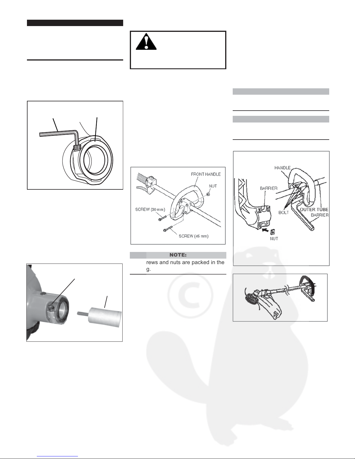
(A) F220
(1) Position the front handle on the
outer pipe where the "Handle
Label" is placed.
(2) Press the handle on the outer
pipe gently so that the handle stays
as shown.
(3) Tighten two 30mm screws on
upper and two 45mm screws on
lower on the handle with nuts.
IMPORTANT!
The terms “left,” “left-hand,” and “LH”,
“right,” “right-hand,” and “RH”; “front” and
“rear” refer to directions as viewed by the
operator during normal operation of this
product.
5-2 Before Assembling
the Outer Tube
(1) Using the hex wrench, Loosen the
joint bolt.
5-3 Assembly of the
Outer Tube
(1). Slip the outer tube into the
joint until the tube bottoms. The
outer tube or gear case shaft may
have to be rotated slightly for the
splines on the main shaft to fully
engage to the engine.
(2). Tighten the joint bolt securely
using the hex wrench.
WARNING!
NEVER operate this
machine without the front
handle. Operating without the front
handle may result in serious injury.
5-4 Assembly of the Handle
NOTE:
The screws and nuts are packed in the
tool bag.
(B) T220
(1) Put 4 square nuts in the frame
of barrier.
(2) Fit the handle and barrier over
the outer tube and tighten four
bolts.
NOTE:
Tighten four bolts in diagonal fashion
for protection of the handle.
NOTE:
Adjust the handle to the best position
for operator comfort.
OUTER
TUBE
JOINT BOLT
HEX
WRENCH
TUBE
CLAMP
8
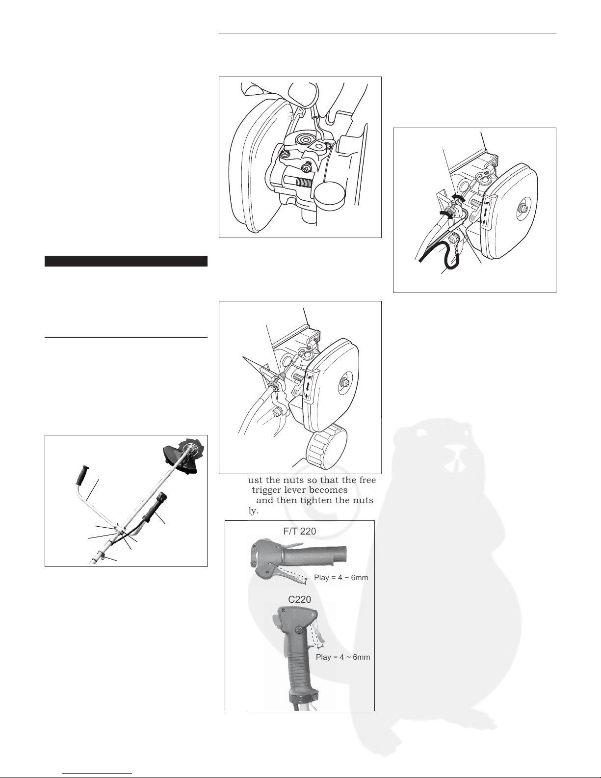
5-5 Throttle Cable Adjustment
(C) C220
(1) Position the handle over the
handle lable on the outer tube.
Make sure the throttle lever is on
the right-hand side of the outer
tube.
(2) Attach the handle mounting
bracket using the two socket-head
cap screws, washers, and lock
washers. At this time, ONLY finger
tighten the screws.
(3) Locate the handle about 5
inches ahead of the shoulder strap
hanger or at the best position for
operator comfort.
IMPORTANT!
Regardless of handlebar location, the aluminum collar must remain in position between the handlebar and the outer tube.
If the collar is omitted or is improperly installed, the handlebar bracket can not be
properly secured.
(4) Using the hex wrench, securely
tighten the two handlebar cap
screws.
(5) Route the ribbed throttle cable
tube along the handlebar and outer
tube. Install the protector sleeve on
the outer tube.
HANDLEBAR
HANDLE BRACKET
HANDLE LABEL
LOWER CAP
BOLT
THROTTLE GRIP
STRAP HANGER
C220
F/T 220
Play = 4 ~ 6mm
Play = 4 ~ 6mm
(1) Hook the end of the throttle
cable to the carburetor.
(2) Place the throttle cable in the
fan cover slot and tighten (finger
tight only) the nuts so that the
nuts are on either side of the slot.
(3) Adjust the nuts so that the free
play of trigger lever becomes
4~6mm and then tighten the nuts
securely.
(4) Fix the earth wire (black) to the
fan cover using the bolt below the fan
cover platform which holds the
throttle cable.
(5) Connect the switch and wire to
the red wire from the engine.
JAM NUTS
(BLACK)
GROUND WIRE
(RED)
IGNITION WIRE
 Loading...