

Shindaiwa B530, BP530, BP530/EC1 Owner's Manual

SHINDAIWA OWNER’S/OPERTOR'S MANUAL
B530 BRUSHCUTTER
WARNING!
Part Number 62108-94310 Rev. 02/05
Read this manual and familiarize yourself with its contents.
This machine is designed for cutting grass, weed, and brush.
Do not use this machine for other purposes.
Minimize the risk of injury to yourself and others.
Do not operate or service this machine unless you clearly understand this
manual.
Keep this manual at a particular place so that you can reread it whenever
you have a question about its use.

2
Throughout this manual are special attention statements.
WARNING!
A statement preceded by the triangular
attention symbol and the word
“W
ARNING” contains information
that should be acted upon to prevent
serious bodily injury
.
CAUTION!
A statement preceded by the word
“CAUTION” contains information
that should be acted upon to prevent
mechanical damage.
IMPORTANT!
A statement preceded by the word
“IMPOR
TANT” is one that possesses
special significance.
NOTE:
A statement preceded by the word “NOTE”
contains information that is handy to know
and may make your job easier.
Attention Statements
IMPORTANT!
The operational procedures described
in this manual are intended to help you
get the most from your unit as well as
to protect you and others from harm.
These procedures are guidelines for safe
operation under most conditions, and are
not intended to replace any safety rules
and/or laws that may be in force in your
area. If you have questions regarding your
Shindaiwa power tool, or if you do not
understand
something in this manual, your
Shindaiwa dealer will be glad to assist
you.
You may also contact Shindaiwa, Inc.
at the address printed on the back of this
manual.
Introduction
Shindaiwa B530 hand held power
equipment has been designed and built to
deliver superior per
formance and reliability
without compromise to quality, comfort,
safety or durability.
Shindaiwa’s high-performance engines
represent the leading edge of 2-cycle
engine technology, delivering exceptionally
high power with remarkably low
displacement and weight. As an owner/
operator
, you’ll soon discover for yourself
why Shindaiwa is simply in a class by itself!
IMPORTANT!
The information contained in this owner's/
operator's manual describes units
available at the time of publication. While
every attempt has been made to give
you the very latest information about your
Shindaiwa product, there may be some
dif
ferences between your machine and the
machine described in this manual.
Shindaiwa Inc. reserves the right
to make changes to products without
prior notice, and without obligation to
make alterations to units pr
eviously
manufactured.
Page
Attention Statements .................................. 2
General Safety Instructions ....................... 3
Safety Labels ................................................ 5
Checking Unit Condition ........................... 5
Unit Description .......................................... 6
Specifications ............................................... 6
Assembly Procedure ................................... 7
Mixing Fuel ............................................... 12
Starting the Engine ................................... 12
Stopping the Engine ................................. 14
Engine Idle Adjustment ............................ 14
Double Shoulder Harness ........................ 14
Operation .................................................. 15
Using a Brush Cutter
W
ith a Trimmer Head .................. 16
Maintenance .............................................. 16
Long T
erm Storage ................................... 18
Blade Sharpening ...................................... 18
Troubleshooting Guide ............................ 19
Declaration of Conformity ........................ 22
Contents
Read and follow this operators
manual. Failure to do so could
result in serious injury
.
Wear head, eye, and hearing
protection during the operation
of this machine.
W
ear non-slip gloves, long
trousers and non-skid boots
during the operation of this
machine.
Make sure no one is within 15
meters of an operating machine.
Beware of thrown objects.
The maximum speed of the
cutting attachment shaft in min
-1
.
Sound Power Level (measured
in accordance with 2000/14/EC)
Warning Labels
Warning labels placed on this unit mean the following:

3
Work Safely
Trimmers and brushcutters operate at very
high speeds and can do serious damage or
injur
y if they are misused or abused. Never
allow a person without training or instr
uc-
tion to operate this unit!
WARNING!
Use Good Judgment
NEVER run the engine when transporting the unit.
NEVER run the engine indoors! Make
sure there is always good ventilation. Fumes from engine exhaust can
cause serious injury or death.
AL
WAYS use the proper cutting tool
for the job.
AL
WAYS stop the unit immediately if
it suddenly begins to vibrate or shake.
Inspect for broken, missing or improperly installed parts or attachments.
NEVER extend trimming line beyond
the length specifi
ed for your unit.
ALWAYS keep the unit as clean as
practical. Keep it free of loose vegetation, mud, etc.
AL
WAYS hold the unit firmly with both
hands when cutting or trimming, and
maintain control at all times.
AL
WAYS keep the handles clean.
AL
WAYS disconnect the spark plug
wire before performing any
maintenance work.
AL
WAYS, if a saw blade should bind
fast in a cut, shut of
f the engine im-
mediately
. Push the branch or tree to
ease the bind and free the blade.
Stay Alert
You must be physically and mentally fit to
operate this unit safely.
General Safety Instructions
WARNING!
Never make unauthorized attachment
installations.
WARNING!
Never operate power equipment of any kind if you are
tired or if you are under the infl
uence of
alcohol, drugs, medication or any other
substance that could af
fect your ability
or judgement.

4
SAFETY
Be Aware of the Working Environment
Avoid long-term
operation in very hot or
very cold weather
.
Make sure bystand-
ers or observers
outside the 15 me-
ter “danger zone”
wear
eye protection.
Be extremely careful of
slippery terrain, especially
during rainy weather
.
Always make sure
the appropriate cutting
attachment shield is
correctly installed.
If contact is made with a hard object, stop the engine
and inspect the cutting attachment for damage.
Be constantly alert for objects and
debris that could be thrown either
from the rotating cutting attachment or
bounced from a hard surface.
Reduce the risk of bystanders being struck
by flying debris. Make sure no one is
within 15 meters — that’
s about 16 paces
— of an operating attachment.
Stop immediately if a child, pet, or person
comes within a 15 meter radius.
Beware of a coasting blade when brushcutting
or edging.
A coasting blade can injure while
it continues to spin after the throttle trigger is
released or after the engine is stopped.
15
METERS
ALWAYS clear your work area of trash or
hidden debris that could be thrown back at
you or toward a bystander
. When operating in
rocky terrain or near electric wires or fences,
use extreme caution to avoid contacting such
items with the cutting attachment.
The Properly Equipped Operator
Always wear a harness when operating
the unit . It adds comfort and helps ensure
safety by limiting movement fore and aft.
When the harness is adjusted properly
,
the unit should balance with the cutting
attachment parallel to the ground.
Always operate with both hands firmly
gripping the unit.
W
ear close-fitting clothing to protect legs and
arms. Gloves offer added protection and are
strongly recommended. Do not wear clothing
or jewelry that could get caught in machinery or
underbrush. Secure long hair so that it is above
shoulder level. NEVER wear shorts!
W
ear hearing protection devices and a broadbrimmed hat or helmet.
A helmet is required when using a blade-equipped
brushcutter to clear small trees.
Always wear eye protection such as
goggles or safety glasses to shield
against thrown objects.
When operating with a blade, make sure the
handle is positioned to provide you with maxi-
mum protection from contacting the blade.
Always make sure the handlebar is installed in
accordance with the manufacturers instructions.
Keep away from the rotating
trimmer line or blade at all
times, and never lift a moving
attachment above waist-high.
Wear appropriate footwear (non-skid boots
or shoes): do not wear open-toed shoes or
sandals. Never work barefooted!
Keep a proper footing and do not overreach.
Maintain your balance at all times during operation.
Always make sure the appropriate cutting attachment
shield is correctly installed and in good condition. Do
not operate the unit if the cutting attachment shield is
missing, loose, or broken.
Long-term exposure to vibration can damage
your hands.
Prolonged exposure to excessive noise is
fatiguing and could lead to impaired hearing.
Do not operate the unit if the
cutting attachment shield is
missing, loose, or broken.

5
Safety Labels
IMPORTANT!
Safety and Operation Information
Labels: Make sure all information labels are undamaged and
readable. Immediately replace
damaged or missing information
labels. New labels are available from your local authorized
Shindaiwa dealer
.
Checking Unit Condition
WARNING!
A cutting attachment shield or other protective device is no guarantee of protection against ricochet. YOU MUST ALWAYS
GUARD AGAINST FLYING DEBRIS!
Use only authorized Shindaiwa parts and accessories with your
Shindaiwa trimmer or brushcutter. Do not make modifications to
this unit without the written approval of Shindaiwa, Inc.
NEVER operate the unit with the cutting attachment shield or
other protective devices (harness, ignition switch, blade retention
clip, etc.) removed!
ALWAYS make sure the cutting attachment is properly installed
and fir
mly tightened before operation.
NEVER use a cracked or warped cutting attachment: If a properly
installed attachment vibrates, r
eplace the attachment with a new
one and re-check.
ALWAYS stop the engine immediately and check for damage if
you strike a for
eign object or if the unit becomes tangled. Do not
operate with broken or damaged equipment.
NEVER allow the engine to run at high RPM without a load. Do-
ing so could damage the engine.
NEVER operate a unit with worn or damaged fasteners or attach-
ment holders.
NEVER cut with a dull blade. Doing so will increase the risk of
blade thr
ust and may also cause equipment damage.

6
Specifications
Unit Description
Outer Tube
Grip
Cutting
Attachment
Shield
Using the accompanying illustrations as
a guide, familiarize yourself with this unit
and its various components. Understanding
the pr
oduct helps ensure top performance,
long service life, and safer operation.
WARNING!
Do not make unauthorized
modifications or alterations to this
machine or any of its components.
Shindaiwa must authorize alterations
and modifi
cations in writing.
Unauthorized modifications or
alterations may alter the machine
operation and could jeopardize
personal safety during operation.
Throttle
Trigger
Gearcase
Tank
Guard
Ignition
Switch
Fuel
T
ank
Spark
Plug
B530 BRUSH CUTTER
Air
Filter
Model Name .............................................................................B530/EC1
Engine Model ..........................................................................................S530EC1
Engine Type .......................................... 2-cycle, vertical cylinder, air cooled
Displacement ............................................................................. 53.2 cm
3
Bore and Stroke ....................................................................... 44x35 mm
Maximum Power Output ................................................................1.7 kW
Engine Speed at Idling ............................................................ 2,500 min
-1
Maximum Engine Speed ........................................................11,000 min
-1
Engine Speed at Maximum Power Output ............................... 7,000 min
-1
Dry Weight (Without cutting attachment and guard.) ...................................9.5 kg
Dimensions (L x H x W) mm ............................................. 1,840x575x455
Fuel Tank Capacity .................................................................... 1,200 ml
Fuel/Oil Ratio .............................. 50:1 with a premium 2-cycle mixing oil
Carburetor Type ............................................ TK, DPW12-2A, Diaphragm
Ignition .............................................. Fully electronic, transistor controlled
Spark Plug ........................................................................... NGK BMR6A
Air Cleaner Type .................................................................Foam element
Starting Method .................................................................. Recoil Starter
Stopping Method .................................................................. Slide Switch
Handle Type ................................................................ Bicycle Handlebar
Sound Pressure Level* (average data between at Idling and at Racing) Note 1 .............90 dB (A)
Sound Power Level** (average data between at Idling and at Racing) Note 1 .............. 105 dB (A)
Vibration Level*** Note 1 Idling (Left/Right) ...............................4.8/4.0 m/s
2
Racing (Left/Right) 5.9/4.6 m/s
2
Sound Pressure Level* (average data between at Idling and at WOT) Note 2 ............... 93 dB (A)
Sound Power Level** (average data between at Idling and at WOT) Note 2 ................ 109 dB (A)
Vibration Level*** Note 2 Idling (Left/Right) ...............................1.8/3.3 m/s
2
WOT (Left/Right) 5.4/6.5 m/s
2
* Sound Pressure Level: In accordance with EN ISO 11806 and ISO 7917
** Sound Power Level In accordance with EN ISO 11806 and ISO 10884
*** Vibration Level: In accordance with EN ISO 11806 and ISO 7916
Note 1: 8-tooth blade equipped.
Note 2: T
rimmer head equipped.

7
Prior to Assembly
Before assembling, make sure you have all
the components required for a complete
unit:
Engine assembly
Outer tube assembly
Debris shield
Double shoulder harness
Cutting attachment
Handlebar
Blade cover
Tool kit, which includes 3mm, 4mm,
and 5mm “L” type hexagonal wr
enches,
8mm/l0mm open-end wrench and
combination spark plug.
T
ool kits vary by model.
Components required for assembly
(cable ties, thr
ottle cable connector, and
throttle cable sleeve).
Carefully inspect all components for
damage.
IMPORTANT!
The terms “left”, “left-hand”, and “LH”;
“right”, “right-hand”, and “RH”; “front” and
“rear” refer to directions as viewed by the
operator during normal operation.
Assembly Procedure
HARNESS
8
Powerhead Assembly
4. Insert the shaft tube assembly into the
powerhead connector clamp. Make sure
the powerhead connector clamp aligns
with the outer tube “Insert up to here”
decal.
5. If necessar
y, rotate the outer tube
assembly until the gearcase output shaft
is pointing down, opposite to the spark
plug.
6. T
ighten the union clamp screw securely.
Install Mainshaft and Outer Tube
Installation Decal
Mainshaft
Outer Tube
B530ES_04
Hex
Wrench
Shim W
asher
Connector Clamp
CAUTION!
Do not remove the D-shaped shim
washer!
The shim washer prevents
damage from overtightening the tube
clamp screw
.
CAUTION!
Do not force the outer tube into the
powerhead! Forcing the outer tube
into the powerhead may damage
the splines on the mainshaft and/or
clutch drum shaft. If installation proves
difficult, rotate the powerhead or
mainshaft until you feel the mainshaft
splines slide into the clutch drum shaft.
1. Place the powerhead on a flat surface,
resting on its stand.
2. Lubricate the mainshaft splines with
molybdenum disulfide (moly) type
gr
ease.
3. Loosen the 6mm socket head cap screw
on the powerhead connector clamp.
Verify that the D-shaped shim washer is
positioned as shown below.
Fan Cover Housing
Powerhead
Tank Guard
1. Remove the 4mm retaining screws and
lower cap from the handlebar bracket.
2. Mount the handlebar on the outer tube
and align it with the “Attach Handle On
This Line” decal.
3. Reinstall the lower cap and r
etaining
bolts. Tighten the retaining screws
evenly.
Handlebar Installation
B530ES_11
Throttle Assembly
Handlebar
Cap
Lower Cap Retaining Screws
Outer T
ube
Installation
Decal
Handlebar Bracket
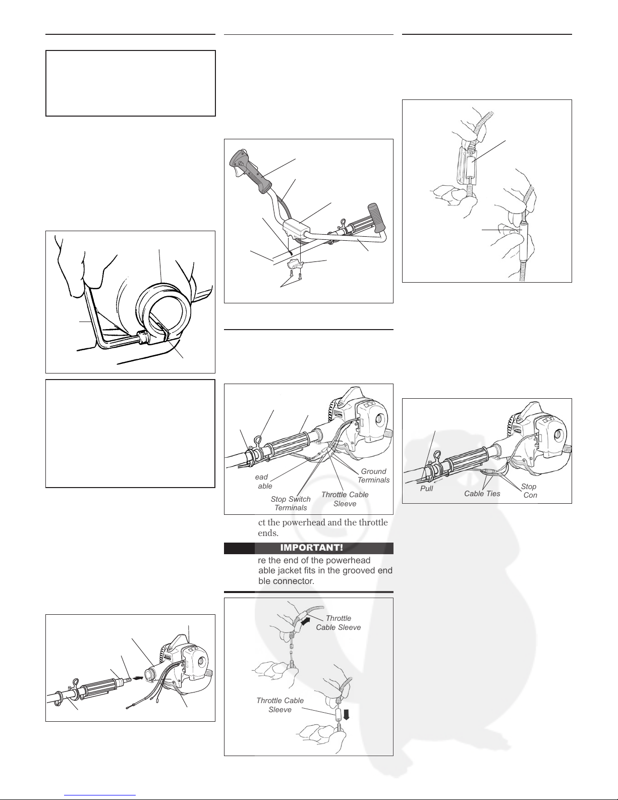
Throttle Cable
Throttle Cable Installation
1. Slide throttle cable and terminal wires
through the cable clamp and grip.
2. Install the throttle cable sleeve on the
powerhead throttle cable.
Cable
Clamp
Hanger
Grip
Powerhead
Throttle Cable
Stop Switch
T
erminals
Throttle Cable
Sleeve
Ground
T
erminals
3. Connect the powerhead and the throttle
cable ends.
IMPORTANT!
Make sure the end of the powerhead
throttle cable jacket fits in the grooved end
of the cable connector
.
Throttle Cable
Sleeve
Throttle
Cable Sleeve
Throttle Cable Installation
(Continued)
(a) Center the throttle cable sleeve over
the connected cable ends and place the
assembly in the thr
ottle cable connector.
(b) Using hand pressure, close the throttle
cable connector.
Throttle Cable
Sleeve
Throttle Cable
Connector
(c) Secure each end of the throttle
connector with a cable tie.
4. Connect the power
head and stop switch
wire terminals.
5. Connect the stop switch ground wire and
the powerhead ground wire terminals.
6. Slide throttle cable and connect terminal
wires into grip by gently pulling on the
throttle cable housing.
Throttle Cable
Housing
Stop Switch
Connector
Cable T
ies
Pull
 Loading...