


English................ |
1 |
Spanish......... |
SP_1 |
French.......... |
FR_1 |
SHINDAIWA OWNER’S/OPERATOR’S MANUAL
DH212 HEDGE TRIMMER
Minimize the risk of injury to yourself and others! Read this manual and familiarize yourself with the
contents. Always wear eye and hearing protection WARNING! when operating this unit.
Part Number 82053 Rev. 6/08
ENGLISH
Introduction
The Shindaiwa DH212 Hedge Trimmer is designed and built to deliver superior performance and reliability without compromise to quality, comfort, safety, or durability. Shindaiwa high performance engines represent the leading edge of 2-cycle engine technology, and deliver exceptionally high power at remarkably low displacement and weight. As a professional owner/operator, you’ll soon discover why Shindaiwa is simply in a class by itself.
the operator’s manual
Read and understand this manual before operation. Keep it in a safe place for future reference. It contains specifications and information for operation, starting, stopping, maintenance, storage, and assembly specific to this product.
Table of Contents |
|
|
Introduction..................................................................... |
2 |
|
- The Operator's Manual............................................. |
2 |
|
- The Safety manual.................................................... |
2 |
|
Safety............................................................................... |
3 |
|
- Manual Safety Symbols and Important Information.... |
3 |
|
- |
International Symbols............................................... |
3 |
- Personal Condition and Safety Equipment............... |
3 |
|
- |
Equipment Check..................................................... |
6 |
Emission Control............................................................. |
8 |
|
Description...................................................................... |
7 |
|
Contents........................................................................... |
9 |
|
Assembly......................................................................... |
9 |
|
- |
Install Blade Stiffener............................................. |
10 |
- |
Remove Blade Stiffener......................................... |
11 |
Operation....................................................................... |
12 |
|
- |
Fuel......................................................................... |
12 |
- |
Starting Cold Engine.............................................. |
13 |
- |
Starting Warm Engine............................................ |
14 |
- |
Stopping Engine..................................................... |
14 |
- |
Hedge Trimming..................................................... |
15 |
Copyright© 2008 By Shindaiwa, Incorporated
All Rights Reserved.
Maintenance.............................................................. |
16 |
|
- |
Skill Levels........................................................ |
16 |
- |
Maintenance Intervals....................................... |
16 |
- |
Air Filter............................................................ |
17 |
- |
Fuel Filter.......................................................... |
17 |
- |
Spark Plug......................................................... |
18 |
- |
Cooling System ................................................ |
18 |
- |
Exhaust System................................................. |
20 |
- |
Carburetor Adjustment...................................... |
21 |
- |
Lubrication........................................................ |
22 |
- |
Sharpening Blades............................................. |
23 |
- |
Blade Adjustment.............................................. |
24 |
Troubleshooting........................................................ |
25 |
|
Storage...................................................................... |
26 |
|
Specifications............................................................ |
27 |
|
Emissions Warranty.................................................. |
28 |
|
IMPORTANT
The information contained in these instructions describes units available at the time of publication.
Shindaiwa Inc. reserves the right to make changes to products without prior notice, and without obligation to make alterations to units previously manufactured.
Safety
manual safety symbols and important information
Throughout this manual and on the product itself, you will find safety alerts and helpful, informational messages preceded by symbols or key words. The following is an explanation of those symbols and key words and what they mean to you.
DANGER
The safety alert symbol accompanied by the word “DANGER” calls attention to an act or condition which WILL lead to serious personal injury or death if not avoided.
WARNING
The safety alert symbol accompanied by the word “WARNING” calls attention to an act or condition which CAN lead to serious personal injury or death if not avoided.
CAUTION
The safety alert symbol accompanied by the word “CAUTION” calls attention to an act or condition which may lead to minor or moderate personal injury if not avoided.
Circle and slash symbol
This symbol means the specific action shown is prohibited. Ignoring these prohibitions can result in serious or fatal injury.
NOTE
This enclosed message provides tips for use, care and maintenance of the unit.
IMPORTANT
The enclosed message provides information necessary for the protection of the unit.
International symbols
Symbol form/shape |
Symbol |
Symbol form/shape |
Symbol |
|
description/application |
description/application |
|||
|
|
|
|
|
|
Read and understand |
|
Fuel and oil mixture |
|
|
owners manual. |
|
|
|
|
|
|
|
|
|
Wear eyes, ears and |
|
Finger Severing |
|
|
head protection |
|
||
|
|
|
|
|
|
|
|
Hot |
|
|
Emergency stop |
|
Surface |
|
|
|
|
|
|
|
|
|
|
|
|
Wear hand protection. |
|
DO NOT smoke |
|
|
|
near fuel. |
|
|
|
Use two handed. |
|
|
|
|
|
|
|
|
|
|
|
|
|
|
Choke Control |
Ignition |
Ignition |
|
|
|
|
||
|
"Cold Start" |
|
ON/OFF |
|
|
Position |
|
|
|
|
(Choke Closed) |
|
|
|
|
|
|
|
|
|
Choke Control |
|
Do not operate |
with- |
|
"Run" |
|
||
|
|
out guards |
in |
|
|
Position |
|
||
|
|
place. |
|
|
|
(Choke Open) |
|
|
|
|
|
|
|
|
Symbol form/shape |
Symbol |
Symbol form/shape |
Symbol |
||
description/application |
description/application |
||||
|
|
|
Carburetor adjustment |
|
Carburetor adjustment |
|
|
|
- Low speed mixture |
|
- High speed mixture |
|
|
|
|
|
|
|
|
|
Safety/Alert |
|
Carburetor adjustment |
|
|
|
|
|
- Idle speed |
|
|
|
|
|
|
|
|
|
Avoid all power |
|
Do not operate closer |
|
|
|
lines. This unit is not |
|
than 15 M (50 ft.) from |
|
|
|
insulated against |
|
electrical hazards. |
|
|
|
electrical current. |
|
|
|
|
|
|
|
|
|
|
|
Plan retreat |
|
Primer bulb |
|
|
|
path from falling |
|
|
|
|
|
objects. |
|
|
|
|
|
|
|
|
|
|
|
DO NOT allow |
|
Wear slip resistant |
|
|
|
|
||
|
|
|
|
||
|
|
|
flames or sparks |
|
foot wear. |
|
|
|
near fuel. |
|
|
|
|
|
|
|
|
|
|
|
|
Keep bystanders at least |
|
|
|
|
|
4.5 meters (15 feet) away. |
|
|
|
|
|
|
|
personal condition and safety equipment
 WARNING
Users of this product risk injury to themselves and others if the unit is used improperly and/or safety precautions are not followed. Proper clothing and safety gear must be worn when operating unit.
ENGLISH

ENGLISH
Physical Condition
Your judgment and physical dexterity may not be good:
•if you are tired or sick,
•if you are taking medication,
•if you have taken alcohol or drugs.
Operate unit only if you are physically and mentally well.
Eye Protection
Wear eye protection that meets ANSI Z87.1 or CE requirements whenever you operate the unit.
Hand Protection
Wear no-slip, heavy-duty work gloves to improve your grip on the handle. Gloves also reduce the transmission of machine vibration to your hands.
Hearing Protection
Shindaiwa recommends wearing hearing protection whenever unit is used.
Proper Clothing
Wear snug fitting, durable clothing;
•Pants should have long legs, shirts with long sleeves.
•DO NOT WEAR SHORTS,
•DO NOT WEAR TIES, SCARFS, JEWELRY.
Wear protective hair covering to contain long hair.
Wear sturdy work shoes with nonskid soles;
•DO NOT WEAR OPEN TOED SHOES,
•DO NOT OPERATE UNIT BAREFOOTED.
Hot Humid Weather
Heavy protective clothing can increase operator fatigue which may lead to heat stroke. Schedule heavy work for early morning or late afternoon hours when temperatures are cooler.
Extended Operation/Extreme Conditions
It is believed that a condition called Raynaud’s Phenomenon, which affects the fingers of certain individuals, may be brought about by exposure to vibration and cold. Exposure to vibration and cold may cause tingling and burning sensations, followed by loss of color and numbness in the fingers. The following precautions are strongly recommended, because the minimum exposure, which might trigger the ailment, is unknown.
•Keep your body warm, especially the head, neck, feet, ankles, hands, and wrists.
•Maintain good blood circulation by performing vigorous arm exercises during frequent work breaks, and also by not smoking.
•Limit the hours of operation. Try to fill each day with jobs where operating the unit or other hand-held power equipment is not required.
•If you experience discomfort, redness, and swelling of the fingers followed by whitening and loss of feeling, consult your physician before further exposing yourself to cold and vibration.
Repetitive Stress Injuries
It is believed that overusing the muscles and tendons of the fingers, hands, arms, and shoulders may cause soreness, swelling, numbness, weakness, and extreme pain in those areas. Certain repetitive hand activities may put you at a high risk for developing a Repetitive Stress Injury (RSI). An extreme RSI condition is Carpal Tunnel Syndrome (CTS), which could occur when your wrist swells and squeezes a vital nerve that runs through the area. Some believe that prolonged exposure to vibration may contribute to CTS. CTS can cause severe pain for months or even years.
To reduce the risk of RSI/CTS, do the following:
•Avoid using your wrist in a bent, extended, or twisted position. Instead try to maintain a straight wrist position. Also, when grasping, use your whole hand, not just the thumb and index finger.
•Take periodic breaks to minimize repetition and rest your hands.
•Reduce the speed and force with which you do the repetitive movement.
•Do exercise to strengthen the hand and arm muscles.
•Immediately stop using all power equipment and consult a doctor if you feel tingling, numbness, or pain in the fingers, hands, wrists, or arms. The sooner RSI/CTS is diagnosed, the more likely permanent nerve and muscle damage can be prevented.
 danger
Do not operate this product indoors or in inadequately ventilated areas. Engine exhaust contains poisonous emissions and can cause serious injury or death.
Read the Manuals
•Provide all users of this equipment with the Operator’s Manual and Safety Manual for instructions on Safe Operation.
Clear the Work Area
•Spectators and fellow workers must be warned, and children and animals prevented from coming nearer than 15 m (50 ft.) while the unit is in use.
Keep a Firm Grip
•Hold the front and rear handles with both hands, with thumbs and fingers encircling the handles.
Keep a Solid Stance
•Maintain footing and balance at all times. Do not stand on slippery, uneven or unstable surfaces. Do not work in odd positions or on ladders. Do not over reach.
Avoid Hot Surfaces
•Keep exhaust area clear of flammable debris. Avoid contact during and immediately after operation.
 warning
Never perform blade maintenance procedures while engine is running.
ENGLISH

ENGLISH
Equipment check
WARNING
Use only Shindaiwa approved attachments. Serious injury may result from the use of a non-approved attachment combination. Shindaiwa, Inc. will not be responsible for the failure of cutting devices, attachments or accessories which have not been tested and approved by Shindaiwa. Read and comply with all safety instructions listed in this manual and safety manual.
•Check unit for loose/missing nuts, bolts, and screws. Tighten and/or replace as needed.
•Inspect fuel lines, tank, and area around carburetor for fuel leaks. DO NOT operate unit if leaks are found.
•Check that the cutting attachment is firmly attached and in safe operating condition.
WARNING
Moving parts can amputate fingers or cause severe injuries. Keep hands, clothing and loose objects away from all openings.
•ALWAYS stop engine, disconnect spark plug, and make sure all moving parts have come to a complete stop before removing obstructions, clearing debris, or servicing unit.
•DO NOT start or operate unit unless all guards and protective covers are properly assembled to unit.
•NEVER reach into any opening while the engine is running. Moving parts may not be visible through openings.
Emission Control
EPA Phase 2/ C.A.R.B. TIER III
The emission control system for the engine is EM/TWC (Engine Modification and 3-way Catalyst) and for the fuel tank the
Control System is EVAP (Evaporative Emissions). Evaporative emission may be applicable to California models only.
IMPORTANT ENGINE INFORMATION
ENGINE FAMILY: 7EHXS.0214EKG DISPLACEMENT: 21.2 cc
EMISSION COMPLIANCE PERIOD : 300 HRS.
THIS ENGINE MEETS U.S. EPA PH2 EXH AND 2007 AND
LATER CALIFORNIA EXH AND EVAP EMISSION REGULA-
TIONS FOR S.O.R.E.. REFER TO OWNER'S MANUAL FOR
MAINTENANCE SPECIFICATIONS AND ADJUSTMENTS.
Emission Control Label (located on Engine) (EXAMPLE ONLY, information on label varies by FAMILY).
PRODUCT EMISSION DURABILITY
The 300 hour emission durability compliance period is the time span selected by the manufacturer certifying the engine emissions output meets applicable emissions regulations, provided that approved maintenance procedures are followed as listed in the Maintenance Section of this manual.
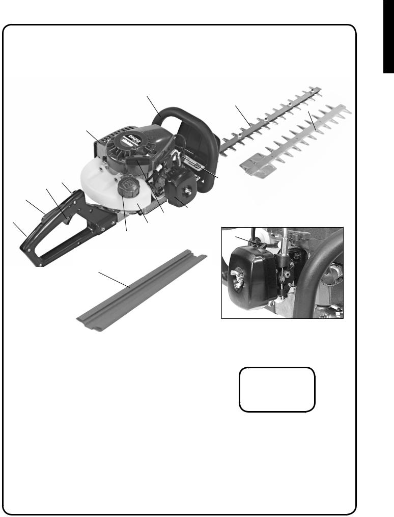
Description
Locate the safety decals on your unit. Make sure the decals are legible and that you understand and follow the instructions on them. If a decal cannot be read, a new one can be ordered from your Shindaiwa dealer.
1
2
3
15
14 |
|
4 |
13 |
|
|
12 |
|
|
11 |
8 |
7 |
|
||
9 |
|
|
10 |
|
|
|
5 |
|
16 |
|
|
6
Right Front Handle Guard |
Hot Decal (near muffler) |
ENGLISH

ENGLISH |
1. |
FRONT HANDLE / GUARD - Comfortable, textured finish provides anti-slip grip for front hand. Guard protects |
|
||
|
|
hand from the blades. Warning decals are located on guard. |
|
2. |
BLADES - Double reciprocating blades mounted to a blade support bar. The blades are double sided, capable of cut- |
|
|
ting on either side. |
|
3. |
BLADE STIFFENER - Attaches to top of blades and guides material being cut into blades. |
|
4. |
SPARK PLUG - Provides spark to ignite fuel mixture. |
|
5. |
CHOKE - The choke control lever is located on the front of the air cleaner case. Move choke lever to "COLD |
|
|
START" ( ) to close the choke for Cold Starting. Move choke lever to "RUN" ( ) position to open choke. |
|
6. |
PURGE BULB - Pumping purge bulb before starting engine draws fresh fuel from the fuel tank, purging air from |
|
|
the carburetor. Pump purge bulb until fuel is visible and flows freely in the clear fuel tank return line. Pump purge |
|
|
bulb an additional 4 or 5 times. |
|
7. |
AIR CLEANER - Contains replaceable filter element. |
|
8. |
RECOIL STARTER HANDLE - Pull handle slowly until recoil starter engages, then quickly and firmly. DO NOT |
|
|
pull rope all the way out or allow the handle to snap back, damage to the starter will occur. |
|
9. |
FUEL TANK - Contains fuel and fuel filter. |
|
10. |
FUEL TANK CAP - Covers and seals fuel tank opening. |
|
11. |
REAR HANDLE - Contains Stop Switch, Throttle Lockout and Throttle Trigger. |
|
12. |
THROTTLE TRIGGER LOCKOUT - This lever must be depressed before Throttle Trigger can be activated. |
|
13. |
THROTTLE TRIGGER - Spring loaded to return to idle when released. Trigger Lockout must be depressed fully |
|
|
before Throttle Trigger will move. During acceleration, depress gradually for best operating technique. |
|
14. |
STOP SWITCH - "TOGGLE SWITCH" located on the left side of the rear handle. Move switch UP to RUN, |
|
|
DOWN to STOP. |
|
15. |
SPARK ARRESTOR - CATALYTIC MUFFLER / MUFFLER -The muffler or catalytic muffler controls exhaust |
|
|
noise and emission. The spark arrestor screen prevents hot, glowing particles of carbon from leaving the muffler. |
|
|
Keep exhaust area clear of flammable debris. |
|
16. |
BLADE COVER - Used to cover blades during transportation or storage. Remove blade cover before using unit. |
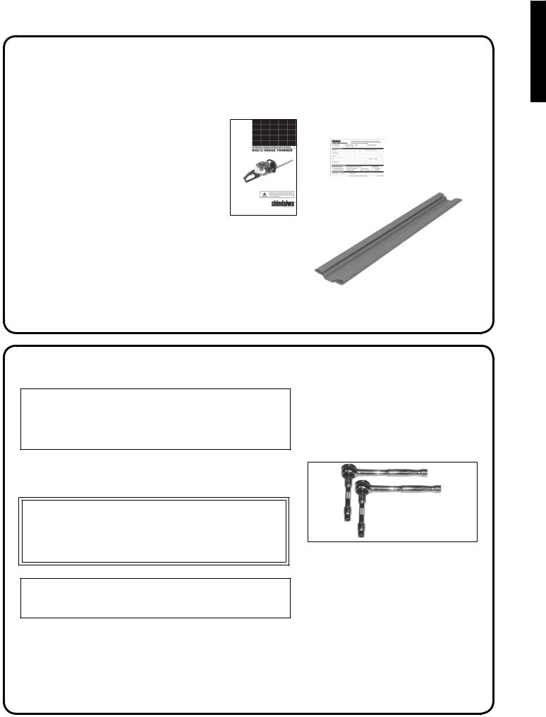
Contents
After opening the carton, check for damage. Immediately notify your retailer or Shindaiwa Dealer of damaged or missing parts. Use the contents list to check for missing parts.
1 - Hedge Trimmer Assembly
1 - Operator’s Manual
1 - Warranty Registration Card
1 - T-Wrench
1 - Blade Stiffener
4 - Blade Locknuts
4 - Stiffener Washers
1 - Blade Cover
ENGLISH
Assembly
Note
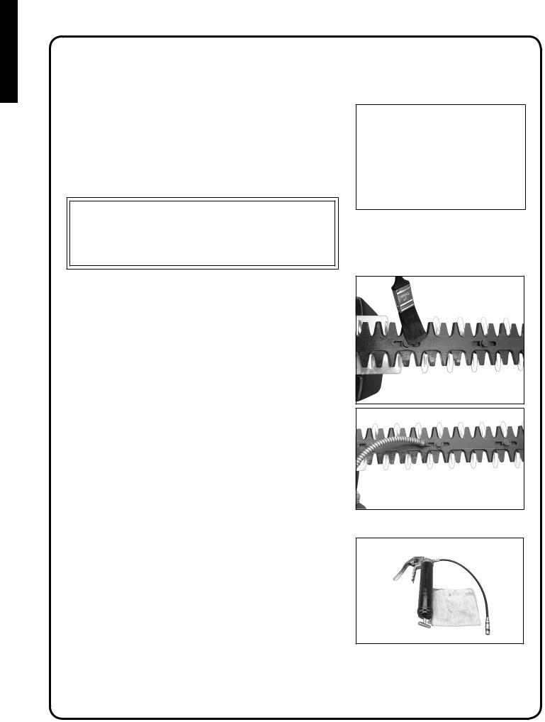
For normal cutting, Shindaiwa strongly recommends the blade stiffener be installed. In extreme conditions, such as commercial cutting, or when cutting thick and/or dense branches, efficiency may be increased by trimming without the blade stiffener.
Tools required: (2) 10 mm Sockets & Extensions
Parts Required: Blade Stiffener, Blade Lock Nuts, Washers
 WARNING
Hedge Trimmer blades are very sharp. Touching them may lead to severe personal injury. Avoid touching blades whenever possible, and always wear gloves to protect hands.
IMPORTANT
Follow blade bolt adjustment instructions exactly. Failure to do so could result in damage to blades or gearbox.
ENGLISH
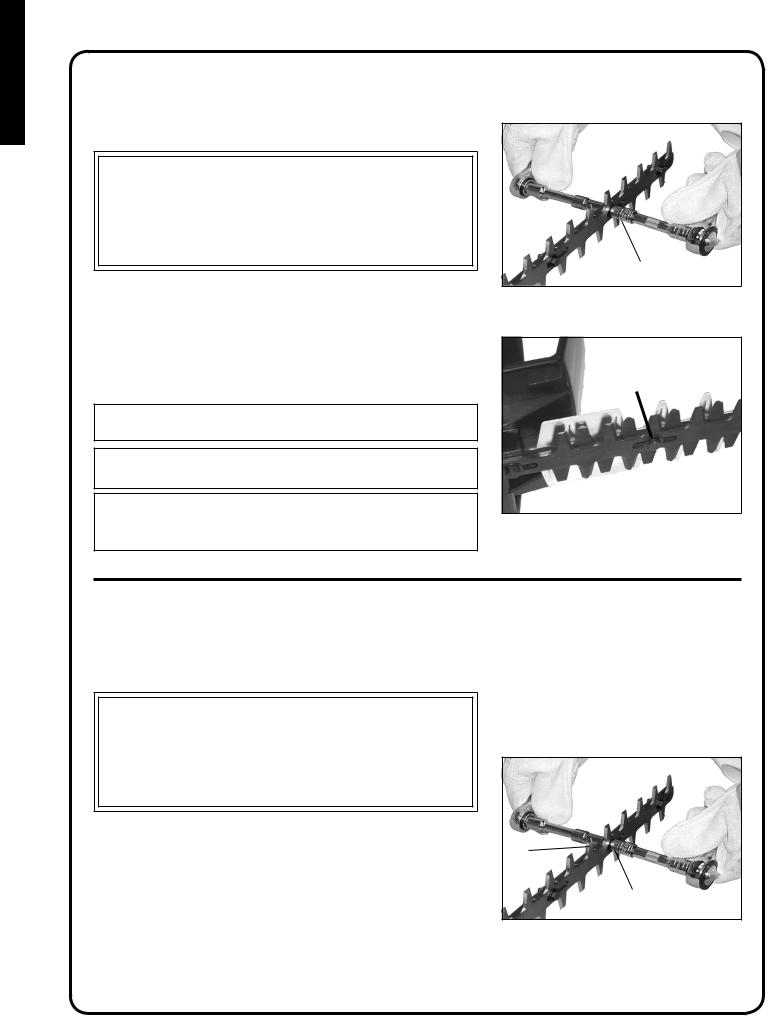
Install blade stiffener
1.Move stop switch to stop position.
2.Disconnect spark plug wire.
WARNING
Hedge trimmer blades are very sharp. Touching them may lead to severe personal injury. Use a socket and extension when adjusting blade bolts or blade locknuts in order to keep hands at a safe distance from sharp blades.
3.Lay unit on muffler side and hold securely in place.
4.Remove first four blade locknuts (A) and washers in front of front handle/guard. Do not remove blade bolts.
5.Tighten blade bolts (B) until snug. Install blade stiffener, then washers.
6.Loosen blade bolts ½ turn. Secure blade stiffener with new locknuts
(A). Hold blade bolts from turning using a 10mm wrench.
Note
Use new locknuts every time blade stiffener is installed.
IMPORTANT
If blade stiffener is damaged or show signs of wear, replace it.
Note
Washers (C) should be movable by hand after blade bolts are adjusted properly.
A 
B
C
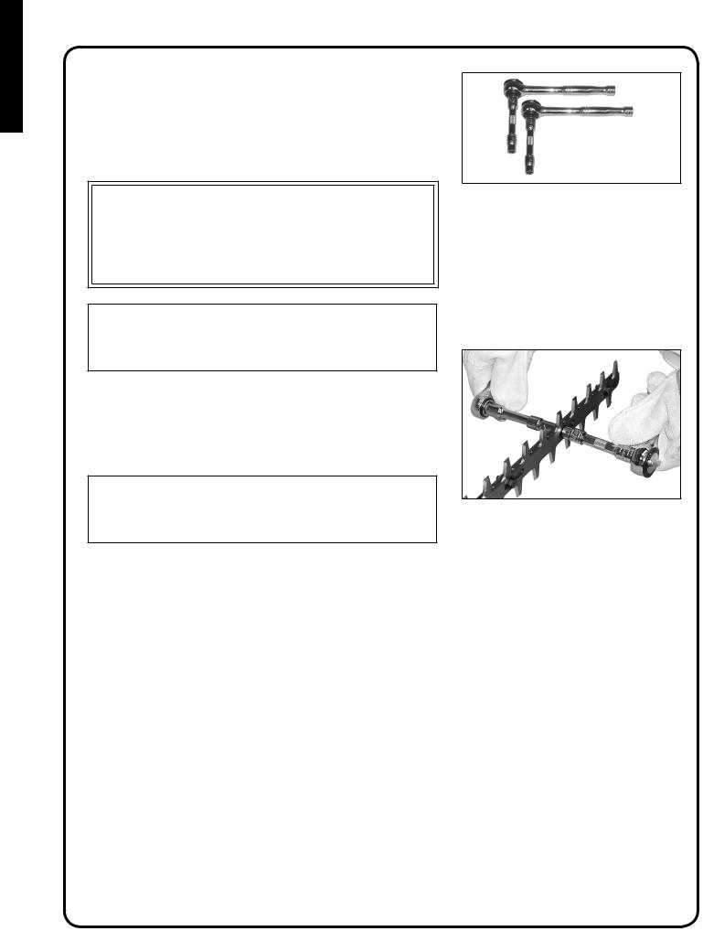
Blade stiffener removal
1.Move stop switch to stop position.
2.Disconnect spark plug wire.
 WARNING
Hedge trimmer blades are very sharp. Touching them may lead to severe personal injury. Use a socket and extension when adjusting blade bolts or blade locknuts in order to keep hands at a safe distance from sharp blades.
3. |
Remove blade stiffener locknuts (A) and washers. |
Do not remove |
|
|
blade bolts. |
|
A |
4. |
Remove blade stiffener. |
|
|
5. |
Tighten blade bolts (B) until snug, then loosen ½ turn. |
B |
|
|
|
|
|
6.Secure blades with new locknuts (A). Hold blade bolts from turning using a 10mm wrench.
10
Operation
WARNING
Moving parts can amputate fingers or cause severe injuries. Keep hands, clothing and loose objects away from all openings. Always stop engine, disconnect spark plug, and make sure all moving parts have come to a complete stop before removing obstructions, clearing debris, or servicing unit.
NOTICE: Use of unmixed, improperly mixed, or fuel older than 90 days, (stale fuel), may cause hard starting, poor performance, or severe engine damage and void the product warranty. Read and follow instructions in the Storage section of this manual.
Fuel
 WARNING
Alternative fuels, such as E-20 (20% ethanol), E-85 (85% ethanol) or any fuels not meeting Shindaiwa requirements are NOT approved for use in Shindaiwa 2-stroke gasoline engines. Use of alternative fuels may cause performance problems, loss of power, overheating, fuel vapor lock, and unintended machine operation, including, but not limited to, improper clutch engagement. Alternative fuels may also cause premature deterioration of fuel lines, gaskets, carburetors and other engine components.
Fuel Requirements
Gasoline - Use 89 Octane [R+M/2] (mid grade or higher) gasoline known to be good quality. Gasoline may contain up to 10% Ethanol (grain alcohol) or 15% MTBE (methyl tertiary-butyl ether). Gasoline containing methanol (wood alcohol) is NOT approved.
IMPORTANT
Mix only enough fuel for your immediate needs! If fuel must be stored longer than 30 days and  oil with fuel stabilizer is not used, it should first be treated with a fuel stabilizer such as STA-BIL™.
 Oil is a registered JASO FC classified oil and also meets or exceeds ISO-L-EGD performance requirements. Shindaiwa One is recommended for use in all Shindaiwa low emissions engines.Shindaiwa One also includes a fuel stabilizer.
ENGLISH
11
ENGLISH
Handling Fuel
 warning
Fuel is VERY flammable. Use extreme care when mixing, storing or handling or serious personal injury may result.
•Use an approved fuel container.
•DO NOT smoke near fuel.
•DO NOT allow flames or sparks near fuel.
•Fuel tanks/cans may be under pressure. Always loosen fuel caps slowly allowing pressure to equalize.
•NEVER refuel a unit when the engine is HOT or RUNNING!
•DO NOT fill fuel tanks indoors. ALWAYS fill fuel tanks outdoors over bare ground.
•DO NOT overfill fuel tank. Wipe up spills immediately.
•Securely tighten fuel tank cap and close fuel container after refueling.
•Inspect for fuel leakage. If fuel leakage is found, do not start or operate unit until leakage is repaired.
•Move at least 3m (10 ft.) from refueling location before starting the engine.
Mixing Instructions
1.Fill an approved fuel container with half of the required amount of gasoline.
2.Add the proper amount of 2-stroke oil to gasoline.
3.Close container and shake to mix oil with gasoline.
4.Add remaining gasoline, close fuel container, and remix.
IMPORTANT
Spilled fuel is a leading cause of hydrocarbon emissions. Some states may require the use of automatic fuel shut-off containers to reduce fuel spillage.
After use
•DO NOT store a unit with fuel in its tank. Leaks can occur. Return unused fuel to an approved fuel storage container.
Storage - Fuel storage laws vary by locality. Contact your local government for the laws affecting your area. As a precaution, store fuel in an approved, airtight container. Store in a well-ventilated, unoccupied building, away from sparks and flames.
IMPORTANT
Stored fuel ages. Do not mix more fuel than you expect to use in thirty (30) days, ninety (90) days when a fuel stabilizer is added.
IMPORTANT
Stored two-stroke fuel may separate. ALWAYS shake fuel container thoroughly before each use.
Fuel to Oil Mix-50:1 Ratio
U.S. METRIC
GAS |
OIL |
GAS |
OIL |
Gallons |
Fl.oz. |
Liter |
cc. |
1 |
2.6 |
4 |
80 |
2 |
5.2 |
8 |
160 |
5 |
13 |
20 |
400 |
12
Starting cold engine
 WARNING
Hedge Trimmer blades are very sharp. Touching them may lead to severe personal injury. Avoid touching blades whenever possible, and always wear gloves to protect hands.
NOTE
The blade cover is used for transportation and storage. Remove blade cover before using the unit.
1.Stop Switch
Move stop switch (A) away from the STOP position.
2.Choke
Move choke (B) to the Cold Start ( ) (CLOSED) position.
3.Purge Bulb
Pump purge bulb (C) until fuel is visible and flows freely in the clear fuel tank return line. Pump bulb an additional 4 or 5 times.
4.Recoil Starter
Lay the unit on a flat, clear area. Grip the front handle securely with one hand, and pull the recoil starter handle (D) until engine fires (or 5 pulls maximum).
5.Choke
After engine fires or 5 pulls, move choke (B) to the RUN ( ) (OPEN) position. Restart engine if necessary and allow unit to warm up at idle for several minutes.
NOTE
If engine does not start with choke in “Run” position after 5 pulls, repeat instructions 2 - 5.
WARNING
The blades must not move at idle, otherwise serious personal injury may result. Periodic carburetor adjustment may be necessary to assure blades do not move at idle.
If blades move, readjust carburetor according to “Carburetor Adjustment” instructions in this manual or see your Shindaiwa Dealer.
6.Throttle Trigger
After engine warm-up, grip the handle to depress the throttle trigger lockout, and gradually depress throttle trigger to increase engine RPM to operating speed.
A
B
C 
D
B
ENGLISH
13

ENGLISH
Starting warm engine
The starting procedure is the same as Cold Start except DO NOT close the choke.
 WARNING
The blades must not move at idle, otherwise serious personal injury may result. Periodic carburetor adjustment may be necessary to assure blades do not move at idle.
If blades move, readjust carburetor according to “Carburetor Adjustment” instructions in this manual or see your Shindaiwa Dealer.
1.Stop Switch
Move stop switch (A) away from the STOP position.
2.Purge Bulb
Pump purge bulb (C) until fuel is visible and flows freely in the clear fuel tank return line. Pump bulb an additional 4 or 5 times.
3.Recoil Starter
Place the unit on a flat, clear area. Grip the front handle securely with one hand, and pull the recoil starter handle (D) until engine starts.
NOTE
If engine does not start after 5 pulls, use Cold Start Procedure.
A
C 
D
Stopping engine |
|
|
|
||
1. |
Throttle |
|
|
Release throttle and allow engine to return to idle before shutting off |
A |
|
engine. |
|
2. |
Stop Switch |
|
|
Move stop switch (A) to STOP position. |
|
 WARNING
If engine does not stop when stop switch is moved to STOP position, close choke - COLD START position - to stall engine. Have your Shindaiwa dealer repair stop switch before using hedge trimmer again.
14
Hedge trimming
 WARNING
Hedge Trimmer blades are very sharp. Touching them may lead to severe personal injury. Avoid touching blades whenever possible, and always wear gloves to protect hands.
1.Hold trimmer firmly and squeeze throttle trigger to accelerate engine.
2.Tilt trimmer so cutting teeth are angled slightly toward the hedge or shrub and proceed to cut.
 warning
Never remove hands from unit when blades are moving.
 warning
The engine continues running even when the blades have stopped due to an obstruction. If this occurs, stop the engine, disconnect ignition cable and remove the obstruction.
Maintenance
 WARNING
Moving parts can amputate fingers or cause severe injuries. Keep hands, clothing and loose objects away from all openings. Always stop engine, disconnect spark plug, and make sure all moving parts have come to a complete stop before removing obstructions, clearing debris, or servicing unit. Allow unit to cool before performing service. Wear gloves to protect hands from sharp edges and hot surfaces.
IMPORTANT
MAINTENANCE, REPLACEMENT OR REPAIR OF EMISSION CONTROL DEVICES AND SYSTEMS MAY BE PERFORMED BY ANY REPAIR ESTABLISHMENT OR INDIVIDUAL, HOWEVER, WARRANTY REPAIRS MUST BE PERFORMED BY A DEALER OR SERVICE CENTER AUTHORIZED BY SHINDAIWA CORPORATION THE USE OF PARTS THAT ARE NOT EQUIVALENT IN PERFORMANCE AND DURABILITY TO AUTHORIZED PARTS MAY IMPAIR THE EFFECTIVENESS OF THE EMISSION CONTROL SYSTEM AND MAY HAVE A BEARING ON THE OUTCOME OF A WARRANTY CLAIM
skill levels
Level 1 = Easy to do. Most required tools come with unit.
Level 2 = Moderate difficulty. Some specialized tools may be required.
Level 3 = Experience required. Specialized tools are required. Shindaiwa recommends that the unit be returned to your Shindaiwa dealer for service.
ENGLISH
15

ENGLISH
Maintenance intervals
COMPONENT/ |
MAINTENANCE |
REQ'D |
DAILY OR |
|
3 |
6 |
YEARLY |
|
EVERY |
MONTHS |
MONTHS |
||||||
SKILL |
BEFORE |
600 |
||||||
SYSTEM |
PROCEDURE |
REFUEL |
OR 90 |
OR 270 |
||||
LEVEL |
USE |
HOURS |
||||||
|
|
|
HOURS |
HOURS |
||||
|
|
|
|
|
|
|||
|
|
|
|
|
|
|
|
|
|
Recommended Shindaiwa Dealer Maintenance Procedures |
|
|
|||||
|
|
|
|
|
|
|
|
|
Cylinder Exhaust Port |
Inspect/Clean/Decarbon |
3 |
|
|
I / C |
|
|
|
|
|
|
|
|
|
|
|
|
Sharpen Blades |
Inspect/Clean |
3 |
I (2) |
|
|
|
|
|
|
|
|
|
|
|
|
|
|
|
Do-It-Yourself Maintenance Procedures |
|
|
|
||||
|
|
|
|
|
|
|
|
|
Air Filter |
Inspect/Clean/Replace |
1 |
I / C |
|
R* |
|
|
|
|
|
|
|
|
|
|
|
|
Choke |
Inspect/Clean |
2 |
I / C |
|
|
|
|
|
|
|
|
|
|
|
|
|
|
Fuel Filter |
Inspect/Replace |
1 |
|
|
I |
|
R * |
|
|
|
|
|
|
|
|
|
|
Fuel System, leaks |
Inspect/Replace |
1 |
I (3) * |
I (3) |
|
|
|
|
|
|
|
|
|
|
|
|
|
Cooling System |
Inspect/Clean |
2 |
I / C |
|
|
|
|
|
|
|
|
|
|
|
|
|
|
Muffler Spark Arrestor |
Inspect/Replace |
2 |
|
|
I / R * |
|
|
|
|
|
|
|
|
|
|
|
|
Gear Housing |
Grease |
2 |
I (1) |
|
|
|
|
|
|
|
|
|
|
|
|
|
|
Blades |
Inspect/Clean |
1 |
I / C (2) |
|
|
|
|
|
|
|
|
|
|
|
|
|
|
Recoil Starter Rope |
Inspect/Clean |
1 |
I / C * |
|
|
|
|
|
|
|
|
|
|
|
|
|
|
Spark Plug |
Inspect/Clean |
2 |
|
|
I / C |
R * |
|
|
|
|
|
|
|
|
|
|
|
Screws/Nuts/Bolts |
Inspect/Tighten/Replace |
1 |
I / R * |
|
|
|
|
|
|
|
|
|
|
|
|
|
|
MAINTENANCE PROCEDURE LETTER CODES: I = INSPECT, R = REPLACE, C = CLEAN
IMPORTANT NOTE - Time intervals shown are maximum. Actual use and your experience will determine the frequency of required maintenance.
MAINTENANCE PROCEDURE NOTES:
(1)Apply high quality lithium -based grease every 15 - 25 hours.
(2)Inspect blade and clean and sharpen as needed. Lubricate blades periodically during use.
(3)Low evaporative fuel tanks DO NOT require regular maintenance to maintain emission integrity. * All recommendations to replace are based on the finding of damage or wear during inspection..
16
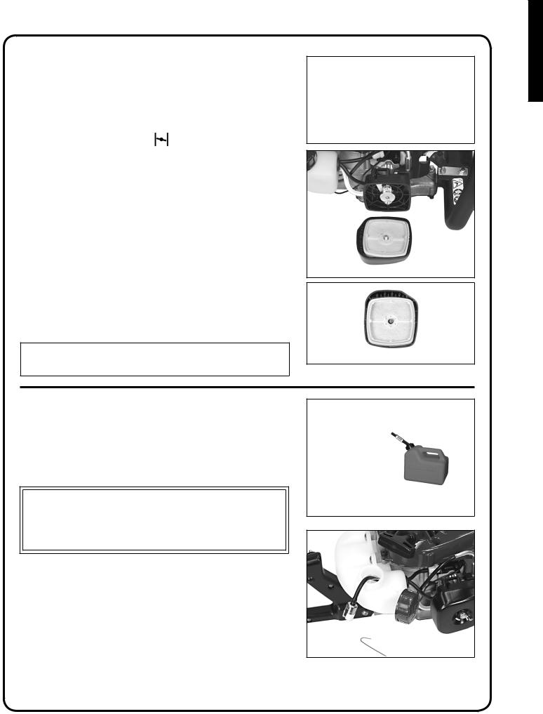
Air filter
Level 1.
Tools required: 25 or 50 mm (1 or 2 in.) cleaning brush
1. Close choke (Cold Start Position [ ). This prevents dirt from entering the carburetor throat when the air filter is removed. Brush accumulated dirt from air cleaner area.
2.Remove air filter cover. Brush dirt from inside cover.
3.Remove air filter and lightly brush debris from filter. Replace filter if it is damaged, fuel soaked, very dirty, or the rubber sealing edges are deformed.
4.If filter can be reused, be certain it:
•Fits tightly in the air filter cavity.
•Is installed with the original side out.
5.Install air filter cover.
NOTE
Carburetor adjustment may be needed after air filter cleaning/replacement.
Fuel filter
Level 1.
Tools required: 200-250 mm (8-10 in.) length of wire with one end bent into a hook, clean rag, funnel, and an approved fuel container
DANGER
Fuel is VERY flammable. Use extreme care when mixing, storing or handling.
1.Use a clean rag to remove loose dirt from around fuel cap and empty fuel tank.
2.Use the “fuel line hook” to pull the fuel line and filter from the tank.
3.Remove the filter from the line and install the new filter.
ENGLISH
17

ENGLISH
Spark plug
Level 2.
Tools required: T-wrench, Feeler gauge, Soft metal brush
IMPORTANT
Use only BPMR-8Y spark plug otherwise severe engine damage may occur.
1.Remove spark plug and check for fouling, worn and rounded center electrode.
2.Clean the plug or replace with a new one. DO NOT sand blast to clean.
Remaining sand will damage engine. |
0.65 mm |
|
|
|
(0.026 in.) |
3.Adjust spark plug gap by bending outer electrode.
4.Tighten spark plug to 150-170 kg/cm (130-150 in. lb.).
Cooling system
Level 2.
Tools required: 3 mm Hex wrench, 25 or 50 mm (1 or 2 in.) cleaning brush
Parts required: None if you are careful.
IMPORTANT
To maintain proper engine operating temperatures, cooling air must pass freely through the cylinder fin area. This flow of air carries combustion heat away from the engine.
Overheating and engine seizure can occur when:
•Air intakes in the crankcase are blocked, preventing cooling air from reaching the cylinder.
•Dust and grass build up on the outside of the cylinder. This build up insulates the engine and prevents the heat from leaving.
Removal of crankcase cooling passage blockages or cleaning of cooling fins is considered “Normal Maintenance.” Any failure attributed to lack of maintenance is not warranted.
18
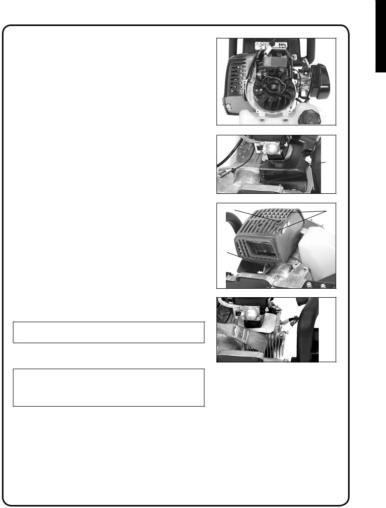
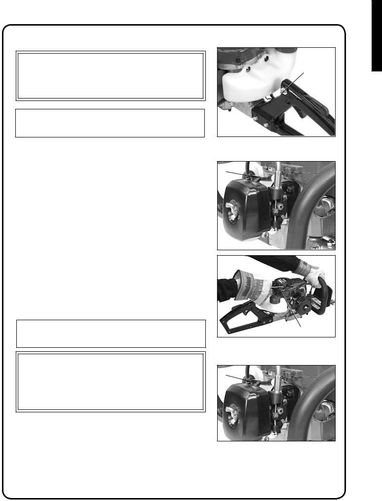
1.Remove spark plug lead and spark plug.
2.Remove (4) starter cover hex socket bolts and starter.
3.Remove bottom right (A) and bottom left (B) hex socket bolts from cylinder cover.
A
4.Remove heat shield bolt (C) from the muffler cover.
5.Carefully pull cylinder cover forward disengaging muffler gasket tabs and ignition lead and lay aside.
C |
D |
|
|
B |
|
6.Loosely install spark plug to keep debris out of the cylinder. Use brush to remove dirt from cylinder fins.
IMPORTANT
DO NOT use a metal scraper to remove dirt from the cylinder fins.
7. Assemble components in reverse order.
NOTE
When installing the cylinder cover, be certain the muffler gasket tabs (D) are locked into the muffler grill slots and the stop switch lead is seated in the rubber grommet.
ENGLISH
19
ENGLISH
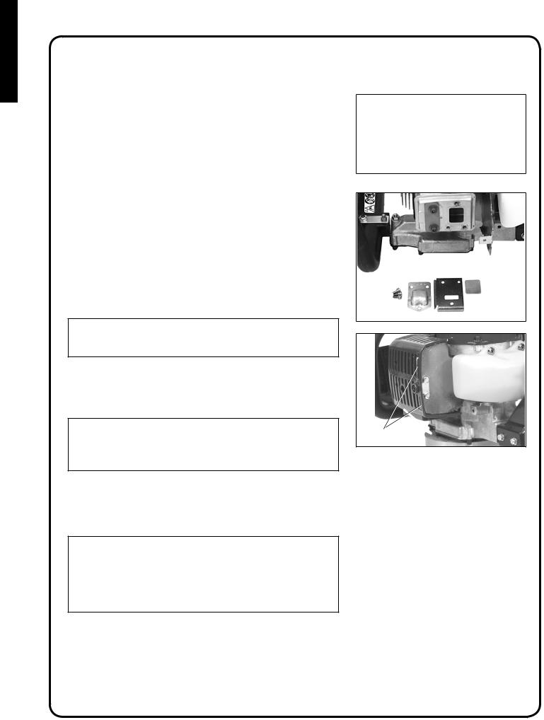
Exhaust system
Spark Arrestor Screen
Level 2.
Tools required: 3 mm Hex wrench, Cross Head Screwdriver, Soft metal brush
Parts required: Screen, Gasket
1.Remove engine cover. See “Cleaning Cooling System” for step by step instructions.
2.Place piston at Top Dead Center (TDC) to prevent carbon/dirt from entering cylinder.
3.Remove exhaust guide (A), gasket (B), and screen (C) from muffler body.
4.Clean carbon deposits from muffler components.
NOTE
When cleaning carbon deposits, be careful not to damage the catalytic element inside muffler.
5.Replace screen if it is cracked, plugged or has holes burned through.
6.Assemble components in reverse order.
NOTE
When installing the cylinder cover, be certain the muffler gasket tabs (D) are locked into the muffler grill slots and the stop switch lead is seated in the rubber grommet.
Cylinder Exhaust Port
Level 3.
IMPORTANT
The cylinder exhaust port must be inspected and cleaned of excess carbon every 3 months or 90 hours of operation in order to maintain this engine within the emissions durability period. Shindaiwa strongly recommends that you return your unit to your Shindaiwa dealer for this important maintenance service.
D
20
Carburetor adjustment
 WARNING
The blades must not move at idle, otherwise serious personal injury may result. Periodic carburetor adjustment may be necessary to assure blades do not move at idle.
If blades move, readjust carburetor according to these instructions, or see your Shindaiwa Dealer.
Engine Break-In
New engines must be operated a minimum duration of two tanks of fuel break-in before carburetor adjustments can be made. During the breakin period your engine performance will increase and exhaust emissions will stabilize. Idle speed can be adjusted as required.
High Altitude Operation
This engine has been factory adjusted to maintain satisfactory starting, emission, and durability performance up to 1,000 feet above mean sea level (MSL). To maintain proper engine operation above 1,000 feet MSL the carburetor must be adjusted by an authorized Shindaiwa service dealer.
Important
If the engine is adjusted for operation above 1,000 feet MSL, the carburetor must be re-adjusted when operating the engine below 1,000 feet MSL, otherwise severe engine damage can result.
Level 2.
Tools required: Screwdriver, Tachometer
Parts required: None.
NOTE
Every unit is run at the factory and the carburetor is set in compliance with emission regulations. This carburetor does not have acceleration and high-speed adjustment needles.
1.Check idle speed and reset if necessary. If a tachometer is available, idle speed screw (A) should be set to the specifications found on page 27 “Specifications” of this manual. Turn idle screw (A) clockwise to increase idle speed; counter clockwise to decrease idle speed.
 WARNING
When carburetor adjustment is completed, the cutting attachment should not move at idle, otherwise serious personal injury may result.
A
ENGLISH
21
ENGLISH
Lubrication
Blades
Level 1.
Tools required: Clean rag, 25 or 50 mm (1 or 2 in.) cleaning brush
Parts required: 20W Engine Oil (lubrication), 50-50 mixture of kerosene and 20W oil (cleaning).
WARNING
Hedge Trimmer blades are very sharp. Touching them may lead to severe personal injury. Avoid touching blades whenever possible, and always wear gloves to protect hands.
1.
1.Move stop switch to stop position.
2.Disconnect spark plug wire from spark plug.
3.Brush loose debris from blade and coat both sides of blade with the 50-50 cleaning mixture.
4.Allow cleaning mixture to soften the remaining gummy residue then wipe it from the blade.
5.Apply clean oil to the entire length of the blade. Be certain the blade bolts are lubricated.
6.Wipe excess oil from the blade before putting the unit back in service.
Gear Box Assembly
Level 1.
Tools required: Grease Gun, Clean rag
Parts required: Lithium Based Grease.
22
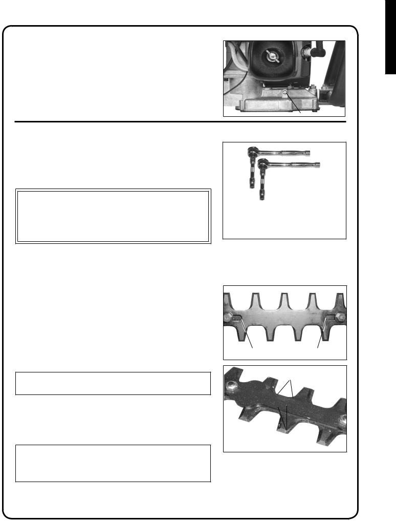
1. Clean dirt from the grease fitting (A).
2. Carefully pump grease into fitting (A). DO NOT force grease. Too much pressure will force grease past seals and cause damage. Apply 1-2 pumps of grease every 15-25 hours of operation.
3. Wipe excess grease from around grease fitting.
A
Sharpening blades
Level 3.
Tools required: (2) 10 mm Sockets & Extensions , Flat file, Screwdriver
Parts required: None
 WARNING
Hedge Trimmer blades are very sharp. Touching them may lead to severe personal injury. Avoid touching blades whenever possible, and always wear gloves to protect hands.
1.Move stop switch to stop position.
2.Disconnect spark plug wire.
3.Remove blade stiffener (see “Blade Stiffener Remove/Install instructions”).
4.Slide blades to allow file clearance using slots (A) on bottom of blade.
Do not pry against cutting edges.
5.File each edge carefully. Follow the original shape of the blade.
IMPORTANT
If a power grinder is used DO NOT allow blade to over heat.
6.Install blade stiffener (see “Blade Stiffener Remove/Install instructions”).
7.Lubricate blades (see “Lubrication instructions”).
IMPORTANT
Blades should only be removed and reinstalled by an Authorized Shindaiwa Servicing Dealer, otherwise premature wear or internal damage may occur.
A A
6mm (.25 in.) Radius
45º
ENGLISH
23
ENGLISH
Blade adjustment
Level 2.
Tools required: (2) 10 mm Sockets and Extensions
Parts required: None
WARNING
Hedge trimmer blades are very sharp. Touching them may lead to severe personal injury. Use a socket and extension when adjusting blade bolts or blade locknuts in order to keep hands at a safe distance from sharp blades.
IMPORTANT
Blades should only be removed and reinstalled by an Authorized Shindaiwa Servicing Dealer, otherwise premature wear or internal damage may occur.
1.Tighten blade bolts until snug, then loosen blade bolts 1/2 turn.
2.Hold blade bolts from turning using 10 mm socket, and tighten blade lock nuts with other 10 mm socket.
note
Locking ability of Hedge Trimmer blade lock nuts will diminish each time they are removed. Replace if turning resistance is not felt when installing locknuts.
24

Troubleshooting
ENGLISH
 DANGER
Fuel vapors are extremely flammable and may cause fire and/or explosion. Never test for ignition spark by grounding spark plug near cylinder plug hole, otherwise serious personal injury may result.
25

ENGLISH
Storage
WARNING
During operation the muffler or catalytic muffler and surrounding cover become hot. Always keep exhaust area clear of flammable debris during transportation or when storing, otherwise serious personal injury may result.
Long Term Storage (over 30 days)
Do not store your unit for a prolonged period of time (30 days or longer) without performing protective storage maintenance which includes the following:
1. Store unit in a dry, dust free place, out of the reach of children.
WARNING
Hedge Trimmer blades are very sharp. Touching them may lead to severe personal injury. Avoid touching blades whenever possible, and always wear gloves to protect hands.
danger
Do not store in enclosure where fuel fumes may accumulate or reach an open flame or spark, otherwise serious personal injury may result.
2. |
Place the stop switch in the “OFF” position. |
9. Remove the spark plug and pour 7cc (1/4 oz.) of fresh, |
|
|
|
clean, two-stroke engine oil into the cylinder through the |
|
3. |
Remove accumulation of grease, oil, dirt and debris from |
spark plug hole. |
|
|
|||
|
exterior of unit. |
A. Place a clean cloth over the spark plug hole. |
|
|
|
||
4. |
Perform all periodic lubrication and services that are |
B. Pull the recoil starter handle 2-3 times to distribute |
|
the oil inside the engine. |
|||
|
required. |
||
|
C. Observe the piston location through the spark |
||
|
|
||
5. |
Apply clean oil to the entire length of the blade. Be |
plug hole. Pull the recoil handle slowly until the |
|
piston reaches the top of its travel and leave it there. |
|||
|
certain the blade bolts are lubricated. |
|
|
6. |
Install blade cover on blades. |
10. Install the spark plug (do not connect ignition cable). |
|
|
|||
7. |
Tighten all the screws and nuts. |
|
|
8. |
Drain the fuel tank completely and pull the recoil starter |
|
|
|
handle several times to remove fuel from the carburetor. |
|
IMPORTANT
Always store and transport hedge trimmers in a stable, horizontal position. Support gear case and cutting blades to prevent excessive flexing, which may cause damage to these components. Always install blade cover when transporting or storing unit.
26

Specifications
MODEL------------------------------------------- |
DH212 |
Length---------------------------------------------- |
1,040 mm (41.0 in.) |
Width----------------------------------------------- |
240 mm (9.45 in.) |
Height---------------------------------------------- |
200 mm (7.87 in.) |
Weight, dry---------------------------------------- |
4.98 kg (11.0 lb.) |
Type of Engine------------------------------------ |
Air cooled, two-stroke, single cylinder, gasoline engine |
Displacement-------------------------------------- |
21.2 cc (1.29 cu.in.) |
Bore------------------------------------------------ |
32.2 mm (1.27 in.) |
Stroke---------------------------------------------- |
26.0 mm (1.02 in.) |
Exhaust System----------------------------------- |
Spark Arrestor Muffler w/catalyst |
Carburetor----------------------------------------- |
Zama w/purge |
Ignition System----------------------------------- |
Flywheel Magneto, Capacitor discharge ignition |
Spark Plug----------------------------------------- |
BPMR-8Y (Gap 0.65 mm (0.026 in.) |
Fuel------------------------------------------------- |
Mixed Fuel - gasoline and oil |
Fuel/Oil Ratio------------------------------------- |
50 : 1 two-stroke, air-cooled engine oil. |
Gasoline-------------------------------------------- |
Use 89 Octane unleaded. Do not use fuel containing methyl alcohol, more |
|
than 10% ethyl alcohol or 15% MTBE. Do not use alternative fuels such as |
|
E-20 or E-85. |
Oil-------------------------------------------------- |
Shindaiwa One Premium Universal 2-Stroke Oil |
Fuel Tank Capacity------------------------------- |
0.5 lit. (16.9 fl. oz) |
Starter System------------------------------------- |
Automatic Recoil Starter |
Clutch---------------------------------------------- |
Centrifugal Type |
Gear Case Ratio----------------------------------- |
5.88:1 |
Cutter----------------------------------------------- |
Double Reciprocating Blade, Double Edge |
Length------------------------------------------- |
490 mm (19.3 in.) |
Pitch---------------------------------------------- |
35 mm (1.38 in.) |
Height-------------------------------------------- |
21 mm (0.83 in.) |
Maximum Diameter Cut |
|
Soft Material------------------------------------- |
25.4 mm (1 in.) |
Woody Material--------------------------------- |
13 mm (1/2 in.) |
Idle Speed (RPM)-------------------------------- |
2,750 - 3,250 |
Clutch Engagement Speed (RPM)------------- |
3,700 - 4,300 |
Wide Open Throttle (RPM)--------------------- |
9,500 - 11,500 |
IMPORTANT This spark ignition system complies with Canadian ICES-002.
ENGLISH
27

ENGLISH
Shindaiwa Corporation
EPA PHASE 2 / CALIFORNIA TIER III EMISSION
CONTROL WARRANTY STATEMENT - WARRANTY RIGHTS AND OBLIGATIONS
The Environmental Protection Agency (EPA) and the California Air Resources Board (C.A.R.B.) and Shindaiwa Inc. are pleased to explain the emission control system warranty on your EPA Phase 2 / C.A.R.B. Tier III model year 2007 and later small off road engine (SORE). New small off road engines must be designed, built and equipped to meet stringent EPA and C.A.R.B. anti-smog standards. Shindaiwa Inc. warrants the emission control system on your small off road engine for the periods of time listed below provided there has been no abuse, neglect or improper maintenance of your small off road engine.
Your emission control system may include parts such as: carburetor/fuel injected system, ignition system, catalytic converter, fuel tank, fuel lines, fuel caps, valves, canisters, filters vapor hoses, clamps connectors, and other associated components. For certain hand-held products with engines less than or equal to 80cc displacement, the fuel tank is subject to the C.A.R.B. evaporative emission control warranty requirements of this section. Contact Shindaiwa Inc. for the models covered under the C.A.R.B. evaporative emission regulations.
Where a warrantable condition exists, Shindaiwa Inc. or its authorized service representative will repair your small off road engine at no cost to you including diagnosis, parts and labor.
MANUFACTURER'S WARRANTY COVERAGE:
The 2007 and later small off road engines are warranted for two years for certain emission related parts. If any emission-related part on your engine is defective, the part will be repaired or replaced by Shindaiwa Inc. or its authorized service representative.
OWNER'S WARRANTY RESPONSIBILITIES:
•As the small off road engine owner, you are responsible for the performance of the required maintenance listed in your Operator's Manual. Shindaiwa Inc. recommends that you retain all receipts covering maintenance on your small off road engine, but Shindaiwa Inc. cannot deny warranty solely for the lack of receipts or for your failure to ensure the performance of all scheduled maintenance.
•As the small off road engine owner, you should however be aware that Shindaiwa Inc. may deny you warranty coverage if your small off road engine or a part has failed due to abuse, neglect, improper maintenance or unapproved modifications.
You are responsible for presenting your small off road engine to Shindaiwa Inc.’s authorized service center as soon as a problem exists. The warranty repairs should be completed in a reasonable amount of time, not to exceed 30 days.
If you have any questions regarding your warranty rights and responsibilities, you can contact Shindaiwa Inc. at 800-521-7733 or www.shindaiwa. com
EPA PHASE 2 / CALIFORNIA TIER III EMISSIONS DEFECT WARRANTY EXPLANATION
This is additional detailed information about the EPA PHASE 2/ CALIFORNIA TIER III EMISSIONS DEFECT WARRANTY for your small off road engine.
WHAT DOES THIS WARRANTY COVER?
Shindaiwa Inc. warrants that your unit was designed, built and equipped to conform with applicable EPA and California emissions standards and that your unit is free from defects in material and workmanship that would cause it to fail to conform with applicable requirements within two (2) years. The warranty period begins on the date the product is delivered
to a retail purchaser. This is your emission control system DEFECTS
WARRANTY.
28
HOW WILL A COVERED PART BE CORRECTED?
If there is a defect in a part covered by this warranty, Shindaiwa Inc.’s authorized service dealer will correct the defect.
You will not have to pay anything to have the part adjusted, repaired or replaced. This includes any labor and diagnosis for warranted repairs performed by the dealer. In addition, engine parts not expressly covered under this warranty but whose failure is a result of a failure of a covered part will be warranted.
Emissions System repairs covered under this warranty should be completed in a reasonable time, not to exceed 30 days.
IMPORTANT
If the diagnosis reveals no defect, the emission defect warranty does not apply.
WHAT PARTS ARE COVERED BY THE EPA PHASE 2/ CALIFORNIA TIER III 2007 & LATER SMALL OFF ROAD ENGINE EMISSIONS DEFECT WARRANTY?
•Any emission related part not scheduled for, "required maintenance" (See Operator’s Manual, "SERVICE MAINTENANCE SCHEDULE") will be repaired or replaced within the warranty period. The repaired or replaced part will be warranted for the remaining Emissions Defect warranty period.
•Any emission related part scheduled for replacement during "required maintenance" (See Operator’s Manual, "SERVICE MAINTENANCE
SCHEDULE") is warranted for the period of time prior to the first scheduled replacement point for that part. Any such part repaired or replaced under warranty shall be warranted for the remainder of the period prior to the first scheduled replacement point for that part.
•Any Shindaiwa Inc. approved replacement part may be used in the performance of any warranty maintenance or repairs on emission-related parts, and must be provided without charge if the part is still under warranty.
•Any replacement part that is equivalent in performance and durability may be used in non-warranty maintenance or repairs, and shall not reduce the warranty obligations of Shindaiwa Inc.
•The owner is responsible for the performance of the required maintenance described in the operator’s manual.
SPECIFIC EMISSION RELATED WARRANTED PARTS:
Choke
Carburetor (complete assembly or replaceable components) Fuel Injection Assembly or replaceable components
Air Filter
Electronic Ignition System Spark Plug
Catalytic Converter / Muffler Assembly
Fuel Tank (CARB only)
WHAT IS NOT COVERED BY THE EPA PHASE 2/ CALIFORNIA TIER III 2007 & LATER SMALL OFF ROAD ENGINE EMISSIONS DEFECT WARRANTY?
•Any failure caused by abuse, neglect, improper maintenance.
•Any failure caused by unapproved modifications, use of unap-
proved add-on parts/modified parts or unapproved accessories.

notes
ENGLISH
29
 Loading...