

Shindaiwa BP45 Owner's And Operator's Manual

SHINDAIWA OWNER’S/OPERATOR’S MANUAL
BP45 BRUSHCUTTER
Part Number 62106-94310 Rev. 3/05
• Read this manual and familiarize yourself with its contents.
• This machine is designed for cutting grass, weed, and brush.
Do not use this machine for other purposes.
• Minimize the risk of injury to yourself and others.
• Do not operate or service this machine unless you clearly understand this manual.
• Keep this manual available at all times so that you can reference it whenever you
have a question about the use of this unit.
WARNING!

2
Throughout this manual are special
attention statements.
WARNING!
A statement preceded by the triangular
attention symbol and the word
“WARNING” contains information
that should be acted upon to prevent
serious bodily injury.
CAUTION!
A statement preceded by the word
“CAUTION” contains information
that should be acted upon to prevent
mechanical damage.
IMPORTANT!
A statement preceded by the word
“IMPORTANT” is one that possesses
special significance.
NOTE:
A statement preceded by the word “NOTE”
contains information that is handy to know
and may make your job easier.
Attention Statements
IMPORTANT!
The operational procedures described
in this manual are intended to help you
get the most from your unit as well as
to protect you and others from harm.
These procedures are guidelines for safe
operation under most conditions, and are
not intended to replace any safety rules
and/or laws that may be in force in your
area. If you have questions regarding your
Shindaiwa power tool, or if you do not
understand something in this manual, your
Shindaiwa dealer will be glad to assist
you. You may also contact Shindaiwa, Inc.
at the address printed on the back of this
manual.
Introduction
The Shindaiwa BP45 Brushcutter has
been designed and built to deliver superior
performance and reliability without
compromise to quality, comfort, safety or
durability.
Shindaiwa’s high-performance engines
represent the leading edge of 2-cycle
engine technology, delivering exceptionally
high power with remarkably low
displacement and weight. As an owner/
operator, you’ll soon discover for yourself
why Shindaiwa is simply in a class by itself!
IMPORTANT!
The information contained in this owner's/
operator's manual describes units
available at the time of publication. While
every attempt has been made to give
you the very latest information about your
Shindaiwa product, there may be some
differences between your machine and the
machine described in this manual.
Shindaiwa Inc. reserves the right to make
changes to products without prior notice,
and without obligation to make alterations
to units previously manufactured.
Page
Attention Statements .................................. 2
General Safety Instructions .......................
3
Safety Labels ................................................ 5
Checking Unit Condition ........................... 5
Unit Description .......................................... 6
Specifications ...............................................
6
Assembly Procedure ...................................
7
Mixing Fuel ............................................... 10
Starting the Engine ...................................
11
Stopping the Engine ................................. 12
Engine Idle Adjustment ............................ 12
Double Shoulder Harness ........................
13
Operation .................................................. 14
Using a Brush Cutter
With a Trimmer Head ............................
15
Maintenance .............................................. 15
Long Term Storage ...................................
17
Blade Sharpening ...................................... 17
Troubleshooting Guide ............................
18
Declaration of Conformity ........................
20
Contents
Read and follow this operators
manual. Failure to do so could
result in serious injury.
Wear head, eye, and hearing
protection during the operation
of this machine.
Wear non-slip gloves, long
trousers and non-skid boots
during the operation of this
machine.
Make sure no one is within 15
meters of an operating machine.
Beware of thrown objects.
The maximum speed of the
cutting attachment shaft in min-1.
Sound Power Level (measured
in accordance with 2000/14/EC)
Warning Labels
Warning labels placed on this unit mean the following:

3
Work Safely
Trimmers and brushcutters operate at very
high speeds and can do serious damage
or injury if they are misused or abused.
Never allow a person without training or
instruction to operate this unit!
WARNING!
Use Good Judgment
NEVER run the engine when transporting the unit.
NEVER run the engine indoors! Make
sure there is always good ventilation.
Fumes from engine exhaust can
cause serious injury or death.
ALWAYS
use the proper cutting tool
for the job.
ALWAYS
stop the unit immediately if
it suddenly begins to vibrate or shake.
Inspect for broken, missing or improperly installed parts or attachments.
NEVER extend trimming line beyond
the length specified for your unit.
ALWAYS
keep the unit as clean as
practical. Keep it free of loose vegetation, mud, etc.
ALWAYS hold the unit firmly with both
hands when cutting or trimming, and
maintain control at all times.
ALWAYS
keep the handles clean.
ALWAYS
disconnect the spark plug
wire before performing any
maintenance work.
ALWAYS
, if a saw blade should bind
fast in a cut, shut off the engine im
mediately. Push the branch or tree to
ease the bind and free the blade.
Stay Alert
You must be physically and mentally fit to
operate this unit safely.
General Safety Instructions
WARNING!
Never make unauthorized attachment
installations.
WARNING!
Never operate power equipment of any kind if you are tired or if
you are under the influence of alcohol,
drugs, medication or any other substance that could affect your ability or
judgement.

4
SAFETY
Be Aware of the Working Environment
Avoid long-term
operation in very hot or
very cold weather.
Make sure bystanders
or observers outside the
15 meter “danger zone”
wear eye protection.
Be extremely careful of
slippery terrain, especially
during rainy weather.
Always make sure
the appropriate cutting
attachment shield is
correctly installed.
If contact is made with a hard object, stop the engine
and inspect the cutting attachment for damage.
Be constantly alert for objects and
debris that could be thrown either
from the rotating cutting attachment or
bounced from a hard surface.
Reduce the risk of bystanders being struck
by flying debris. Make sure no one is
within 15 meters — that’s about 16 paces
— of an operating attachment.
Stop immediately if a child, pet, or person
comes within a 15 meter radius.
Beware of a coasting blade when
brushcutting or edging. A coasting blade
can injure while it continues to spin after
the throttle trigger is released or after the
engine is stopped.
15
METERS
ALWAYS clear your work area of trash or
hidden debris that could be thrown back at
you or toward a bystander. When operating in
rocky terrain or near electric wires or fences,
use extreme caution to avoid contacting such
items with the cutting attachment.
The Properly Equipped Operator
Always wear a harness when operating
the unit . It adds comfort and helps ensure
safety by limiting movement fore and aft.
When the harness is adjusted properly,
the unit should balance with the cutting
attachment parallel to the ground.
Always operate with both hands firmly
gripping the unit.
Wear close-fitting clothing to
protect legs and arms. Gloves offer
added protection and are strongly
recommended. Do not wear clothing
or jewelry that could get caught in
machinery or underbrush. Secure long
hair so that it is above shoulder level.
NEVER wear shorts!
Wear hearing protection devices and a broadbrimmed hat or helmet.
A helmet is required when using a blade-equipped
brushcutter to clear small trees.
Always wear eye protection such as
goggles or safety glasses to shield
against thrown objects.
When operating with a blade, make sure the
handle is positioned to provide you with maxi-
mum protection from contacting the blade.
Always make sure the handlebar is installed in
accordance with the manufacturers instructions.
Keep away from the rotating
trimmer line or blade at all
times, and never lift a moving
attachment above waist-high.
Wear appropriate footwear (non-skid boots
or shoes): do not wear open-toed shoes or
sandals. Never work barefooted!
Keep a proper footing and do not overreach.
Maintain your balance at all times during operation.
Always make sure the appropriate cutting
attachment shield is correctly installed and
in good condition. Do not operate the unit
if the cutting attachment shield is missing,
loose, or broken.
Long-term exposure to vibration can damage
your hands.
Prolonged exposure to excessive noise is
fatiguing and could lead to impaired hearing.
Do not operate the unit if the
cutting attachment shield is
missing, loose, or broken.

5
Safety Labels
IMPORTANT!
Safety and Operation Information
Labels: Make sure all information
labels are undamaged and
readable. Immediately replace
damaged or missing information
labels. New labels are available
from your local authorized
Shindaiwa dealer.
Checking Unit Condition
WARNING!
A cutting attachment shield or other protective device is no guarantee of protection against ricochet. YOU MUST ALWAYS
GUARD AGAINST FLYING DEBRIS!
Use only authorized Shindaiwa parts and
accessories with your Shindaiwa trimmer
or brushcutter. Do not make modifications
to this unit without the written approval of
Shindaiwa, Inc.
NEVER operate the unit with the cutting attachment shield or other protective
devices (harness, ignition switch, blade
retention clip, etc.) removed!
ALWAYS make sure the cutting attachment is properly installed and firmly tight
-
ened before operation.
NEVER use a cracked or warped cutting
attachment: If a properly installed attach
ment vibrates, replace the attachment with
a new one and re-check.
ALWAYS stop the engine immediately and
check for damage if you strike a foreign
object or if the unit becomes tangled. Do
not operate with broken or damaged equip
-
ment.
NEVER allow the engine to run at high
RPM without a load. Doing so could damage the engine.
NEVER operate a unit with worn or damaged fasteners or attachment holders.
NEVER cut with a dull blade. Doing so will
increase the risk of blade thrust and may
also cause equipment damage.
6
Specifications
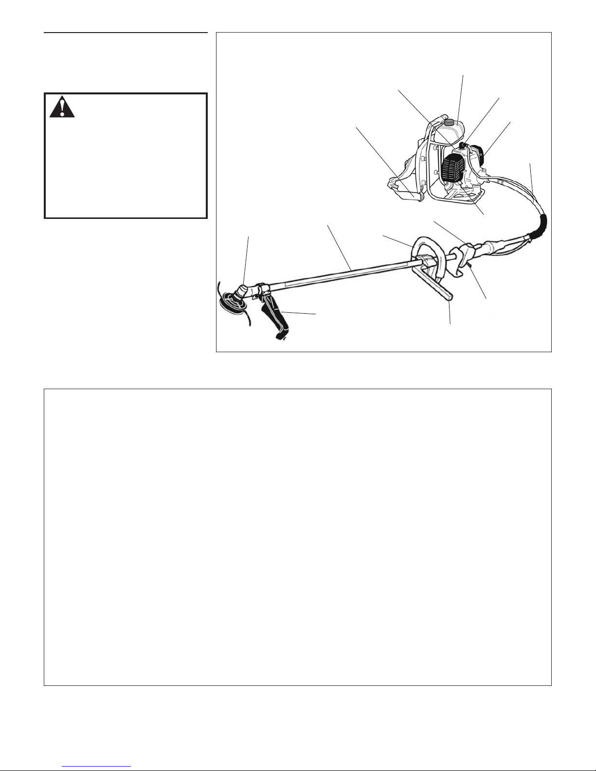
Unit Description
Caution Label
Barrier
Cutting Attachment
Shield
Using the accompanying illustrations as
a guide, familiarize yourself with this unit
and its various components. Understanding
the product helps ensure top performance,
long service life, and safer operation.
WARNING!
Do not make unauthorized
modifications or alterations to this
machine or any of its components.
Shindaiwa must authorize alterations
and modifications in writing.
Unauthorized modifications or
alterations may alter the machine
operation and could jeopardize
personal safety during operation.
ON-OFF
Switch
Gearcase
Harness with
Emergency Release
Spark
Plug
BP45 BRUSH CUTTER
Model Name .............................................................................BP45/EC1
Engine Model .......................................................................... SBP45EC1
Engine Type ..........................................2-cycle, vertical-cylinder, air-cooled
Displacement ............................................................................. 41.5 cm
3
Bore and Stroke ......................................................................40 x 33 mm
Maximum Power Output ................................................................1.4 kW
Engine Speed at Idling ............................................................ 2,500 min
-1
Maximum Engine Speed ........................................................11,500 min
-1
Engine Speed at Maximum Power Output ............................... 6,500 min
-1
Dry Weight (Without cutting attachment and guard) ...................................9.7 kg
Dimensions (L x H x W) mm ......................................... 2,720 x 365 x 405
Fuel Tank Capacity ...................................................................1,400 cm
3
Fuel/Oil Ratio .............................. 50:1 with a premium 2-cycle mixing oil
Carburetor Type .................................................................... TK, PC1OW
Ignition .............................................. Fully electronic, transistor controlled
Spark Plug ........................................................................... NGK BMR6A
Air Cleaner Type .................................................................Foam element
Starting Method .................................................................. Recoil Starter
Stopping Method .................................................................. Slide Switch
Handle Type .................................................. Loop type handle w/barrier
Sound Pressure Level* (average data between at Idling and at Racing) Note 1 .............83 dB (A)
Sound Power Level** (average data between at Idling and at Racing) Note 1 ........... 103 dB (A)
Vibration Level*** Note 1 Idling (Left/Right) ...............................0.6/0.7 m/s
2
Racing (Left/Right) 2.6/2.7 m/s
2
Sound Pressure Level* (average data between at Idling and at WOT) Note 2 ............... 93 dB (A)
Sound Power Level** (average data between at Idling and at WOT) Note 2 ............. 105 dB (A)
Vibration Level*** Note 2 Idling (Left/Right) ...............................0.7/0.6 m/s
2
WOT (Left/Right) 1.4/2.0 m/s
2
* Sound Pressure Level: In accordance with EN ISO 14865 and ISO 7917
** Sound Power Level In accordance with EN ISO 14865 and ISO 10884
*** Vibration Level: In accordance with EN ISO 14865 and ISO 7916
Note 1: 8-tooth blade equipped.
Note 2: Trimmer head equipped.
Throttle Lever
Flex
Cable
Fuel Tank
Muffler
Cylinder
Cover
Air
Cleaner
Handle
7
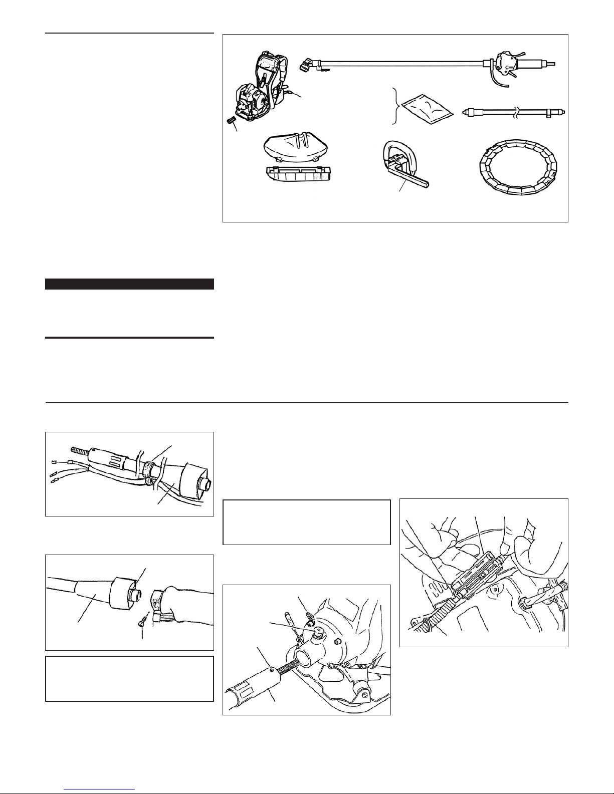
Prior to Assembly
Before assembling, make sure you have all
the components required for a complete
unit:
Engine assembly
Outer tube assembly
Debris shield
Cutting attachment
Loop Handle and Barrier
Blade cover
Tool kit, which includes 4 mm and 5 mm
“L” type hexagonal wrenches, 8 mm/
l0 mm open-end wrench and
combination spark plug/ tool holder
wrench. Tool kits vary by model.
Components required for assembly
(throttle cable connector).
Carefully inspect all components for
damage.
IMPORTANT!
The terms “left”, “left-hand”, and “LH”;
“right”, “right-hand”, and “RH”; “front” and
“rear” refer to directions as viewed by the
operator during normal operation.
Assembly Procedure
Engine Assembly
Outer Tube Assembly
Harness
Connector
Guard
Barrier
Blade Cover
Flexible Pipe
Handle
Tool Set
Hex Wrench (M5)
Hex Wrench (M6)
Plug Wrench
Spanner Wrench
Assembly of the Flexible Pipe
1. Put the flexible pipe through the holder
hole.
CAUTION!
Make sure the inserting direction of the
flexible pipe is correct as shown.
CAUTION!
Pull the flexible pipe and make sure it is
securely locked by the stopper knob.
Holder
Flexible Pipe
2. Loosen the bolt of the outer tube and
insert the O-ring of the flexible pipe into
the outer tube.
O-Ring
Bolt
Flexible Pipe
3. Make sure the groove of the flexible
pipe aligns with the bolt, and then
tighten the bolt. Make sure the flexible
pipe does not come off the outer tube.
4. Insert the other end of the flexible pipe
straight into the engine to the end. (It is
not necessary to pull the stopper knob
when doing this.)
5. Make sure the stopper knob is in the
hole of the flexible pipe and it is securely
locked.
Cable Holder
Stopper Knob
Flexible Pipe
Hole
6. Put the throttle cable (flexible pipe
side) through the cable holder, and
then connect the throttle cables in the
connector as shown.
7. Connect the red wire from the engine
to the white wire from the throttle, and
connect the black wire from the engine
to the black wire from the throttle.
Throttle
Cable
Connector
Cable Holder
8
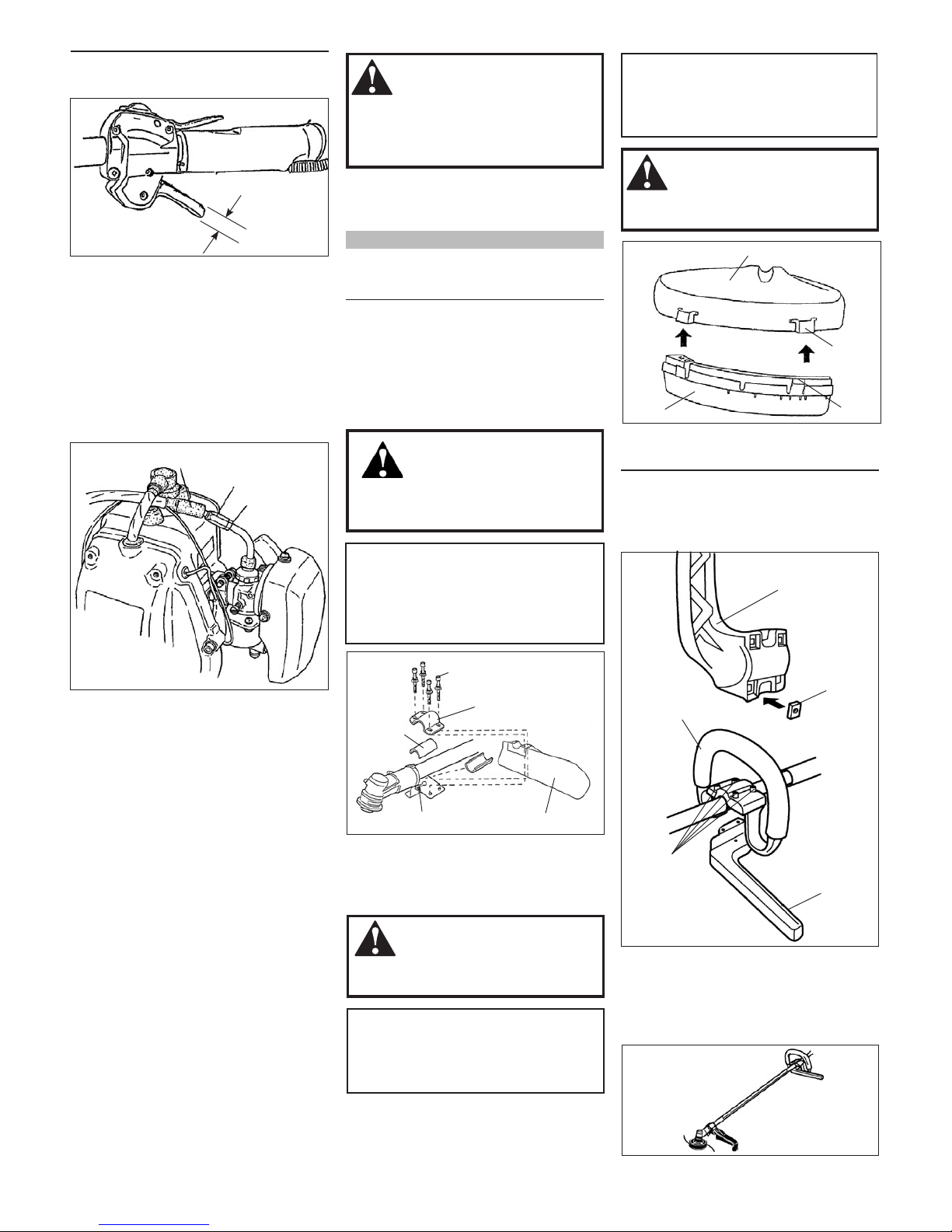
Throttle Cable Adjustment
WARNING!
NEVER operate this machine
without the cutting attachment shield.
Operating without the cutting attach
ment shield may result in serious
injury.
Cutting Attachment Shield Assembly
1. Insert the cutting attachment shield
between the outer tube and the lower
clamp.
NOTE:
It may be necessary to loosen the lower
clamp bolt so that the shield will fit between
the tube and clamp.
2. Fit the upper clamp over the outer pipe
and install four bolts finger tight.
3. Tighten the lower clamp bolt and nut
securely.
4. Securely tighten four upper clamp bolts in
a crisscross fashion.
Sub-Shield
(when trimmer head is in use)
1. Attach the shield extension to the
cutting attachment shield.
CAUTION!
Make sure the sub-guard is
completely hooked at the hook
receiver.
WARNING!
NEVER use this machine without
sub-shield when using a trimmer
head.
WARNING!
Carefully inspect the gearcase
and cutting attachment shield assembly
to make sure they are tightened securely
and do not wobble.
CAUTION!
Ma ke s ure t he c lamp scre w and
retaining nut are securely tightened
before tightening the four socket head
cap screws.
CAUTION!
The line cutter is attached to the shield
extension and must be used when
operating with a trimmer head.
WARNING!
The line cutter is very sharp.
When handling, wear gloves to protect
your hands.
Assembly of the Handle
1. Put the 4 square nuts in the frame of the
barrier.
2. Fit the handle and barrier over the
outer tube and tighten the four bolts.
Square Nut
Barrier
Handle
Bolt
Barrier
3. Position the handle at the best position
for operator comfort.
4. Secure the handle by alternately
tightening the 4 bolts in a diagonal or
crisscross fashion.
Cutting Attachment Shield
Hook
Receiver
Hook
Sub-shield
1. Pulling the throttle trigger gently, make
sure the play is about 5 mm.
Play = 5 mm
2. If the play is too long or too short:
(a) Slide the cable cap toward the
muffler side until the adjusting nut
and the lock nut appear.
(b) Loosen the lock nut slightly.
(c) Turn the adjusting nut so that the
play becomes about 5 mm.
(d) Tighten the lock nut.
(e) Finally, slide the cable cap back.
Cable Cap
Adjusting
Nut
Lock Nut
Bolt
Upper Clamp
Spacer
Nut Safety Guard
 Loading...