

Shindaiwa BP35 Owner's Manual
1Top cover
SHINDAIWA OWNER'S/OPERATOR'S
MANUAL
BRUSHCUTTER
English
Español
Português
WARNING
Read the instructions carefully and follow the rules for safe
operation.
Failure to do so could result in serious injury.

2
Introduction
2Introduction
shindaiwa Brushcutters are lightweight, high-performance, petrol engined units designed for weed control, grass trimming and
brush cutting in areas difficult to control by any other means.
Do not use this unit for any purpose other than aforementioned.
Never let children operate this unit.
This Manual provides the information necessary for assembly, operation and maintenance.
You must read this Manual to understand the safe and effective operation of your shindaiwa product.
For future reference, you should keep this Operator's Manual.
If this Operator's Manual has become illegible through impairment or is lost, please purchase a new one from your shindaiwa
dealer.
When renting or lending this machine to a person who will operate it, always include this Operator's Manual, which provides
explanation and instructions.
When transferring a product, please deliver it attaching the Operator's Manual.
Specifications, descriptions and illustrative material in this literature are as accurate as known at the time of publication, but are
subject to change without notice.
Illustrations may include optional equipment and accessories, and may not include all standard equipment.
If there is any clause in this Manual that is hard to be understood, please contact your shindaiwa dealer.

3
Contents
Decals and symbols............................................................................................................ 4
Rules for safe operation...................................................................................................... 5
Training.......................................................................................................................... 5
Eye protection................................................................................................................ 5
Hearing and ear protection ............................................................................................ 5
Protective clothing ......................................................................................................... 5
Additional protection ...................................................................................................... 5
Shoulder harness .......................................................................................................... 6
Fuel................................................................................................................................ 7
Physical condition .......................................................................................................... 7
Area and equipment inspection ..................................................................................... 7
General operation .......................................................................................................... 8
Vibration and cold ........................................................................................................ 10
Repetitive stress injuries.............................................................................................. 10
Rules for safe operation with metal blade......................................................................... 11
Use correct blade......................................................................................................... 11
Reaction forces............................................................................................................ 12
Blade selection ............................................................................................................ 12
Rules for safe operation with nylon line cutting head ....................................................... 13
Use correct cutting attachment .................................................................................... 13
Description........................................................................................................................ 15
Assembling ....................................................................................................................... 16
Drive shaft installation.................................................................................................. 16
Loop handle installation ............................................................................................... 16
Throttle linkage ............................................................................................................ 16
Shield installation......................................................................................................... 17
Installing blade............................................................................................................. 17
Guard plate installation ................................................................................................ 18
Nylon line head installation .......................................................................................... 18
Fuel................................................................................................................................... 19
Fuel.............................................................................................................................. 19
Handling fuel................................................................................................................ 19
Operation .......................................................................................................................... 20
Starting the cold engine ............................................................................................... 20
Starting the warm engine............................................................................................. 20
Stopping the engine..................................................................................................... 21
Left hand operation...................................................................................................... 21
Service maintenance guide .............................................................................................. 22
Troubleshooting ................................................................................................................ 23
Maintenance and care ...................................................................................................... 24
Cleaning air filter.......................................................................................................... 24
Check fuel system ....................................................................................................... 24
Replacing fuel filter ...................................................................................................... 24
Check spark plug ......................................................................................................... 24
Cooling system maintenance....................................................................................... 24
Carburettor adjustment ................................................................................................ 25
Cleaning silencer ......................................................................................................... 25
Angle transmission ...................................................................................................... 25
Lubricating drive shaft (flexible shaft) .......................................................................... 25
Storage ............................................................................................................................. 26
Long term storage (Over 30 days)............................................................................... 26
Disposal procedure ........................................................................................................... 27
Specifications.................................................................................................................... 28
4
Decals and symbols
Locate this safety decal on your unit.
The complete unit illustration found in the "Description" section will help you locate them.
Make sure the decal is legible and that you understand and follow the instructions on it.
If a decal cannot be read, a new one can be ordered from your shindaiwa dealer.
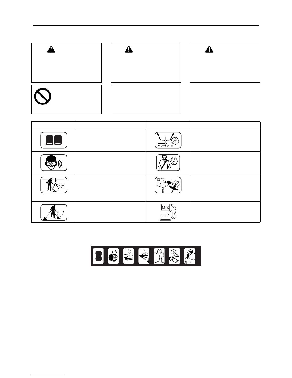
DANGER WARNING CAUTION
This symbol accompanied by the
word "DANGER" calls attentions to
an act or a condition which will
lead to serious personal injury or
death of operators and bystanders.
This symbol accompanied by the
word "WARNING" calls attentions
to an act or a condition which can
lead to serious personal injury or
death of operators and bystanders.
"CAUTION" indicates a potentially
hazardous situation which, if not
avoided, may result in minor or
moderate injury.
Circle and slash symbol
means whatever is
shown is prohibited.
NOTE
This enclosed message provide tips
for use, care and maintenance of the
unit.
Symbol form / shape Symbol description / application Symbol form / shape Symbol description / application
Read and follow this Operator's
Manual.
Failure to do so could result serious
injury.
Do not operate this unit with a blade
unless the unit is equipped with a
shindaiwa-approved handlebar or
barrier.
Wear eye and hearing protection at
all times during the operation of this
unit.
Always wear a harness when
operating this unit with a blade.
A harness is also recommended
when using trimmer line.
Keep bystanders at least 15 m away
during operation.
If unit is used as a brushcutter,
beware of blade thrust.
A jammed blade can cause the unit to
jerk suddenly and may cause the
operator to lose control of the unit.
Beware of thrown or ricocheted
objects.
Petrol and oil mixture
Part number X505-005890
5
Rules for safe operation
Training
Do not permit operation without proper training and protective equipment.
Read the Operator's Manual carefully.
Be thoroughly familiar with the controls and proper use of the unit.
Know how to stop the unit and shut off the engine.
Never allow anyone to use the unit without proper instruction.
If you have any questions or problems, please contact your shindaiwa dealer.
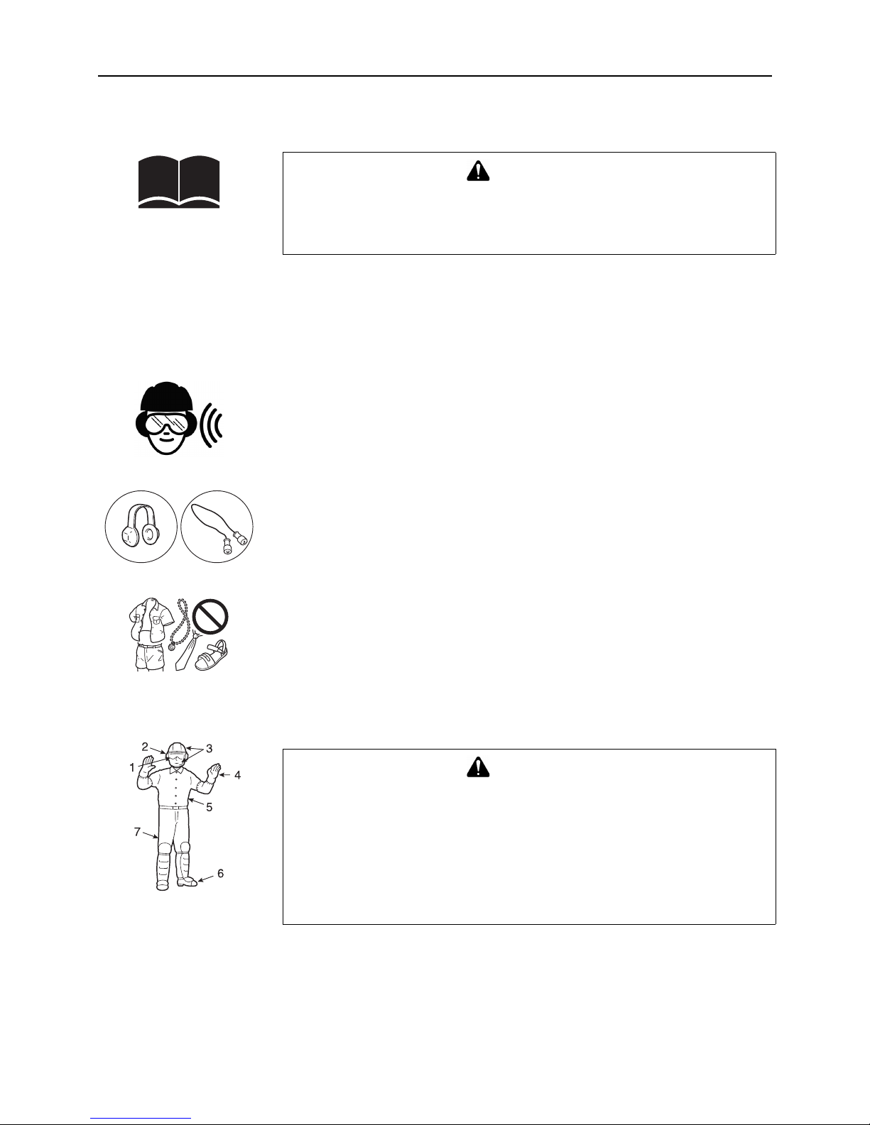
Eye protection
The operator must wear eye protection not only against objects thrown by the unit, but also
because eye infections can be caused by airborne dust, seeds and pollen.
Prescription glasses may be worn under the safety goggles.
Eye protection should also be worn by persons in the risk zone which extends beyond the
danger zone.
Hearing and ear protection
Prolonged exposure to loud noise can cause impairment or loss of hearing.
Wear a suitable hearing protective device such as earmuffs or earplugs to protect against
objectionable or uncomfortable loud noises.
Protective clothing
Choose trousers, shirts and jackets that fit trimly and have no strings, frills or dangling straps
which could catch on the unit or the underbrush.
Do not wear ties, loose clothing or jewellery.
Keep clothing buttoned or zipped up and shirttails tucked in.
Secure hair so it is above shoulder length.
The wearing of gloves offers some protection against contact with skin irritants such as poison
ivy.
Soft leather work gloves may also improve your grip.
Additional protection
1. Safety goggles. 2. Hearing protectors. 3. Head and face protection.
4. Safety gloves. 5. Trim-fitting clothes. 6. Sturdy shoes or boots.
7. Long trousers.
Hay fever (Rhinitis) sufferers may wear disposable masks to help reducing the intake of
allergenic particles.
WARNING
Grass trimmers and brushcutters can throw small gravel, stone, glass, metal or
plastic objects as well as the material being cut.
Read these "Rules for safe operation" with care.
Follow instructions in the Operator's Manual.
WARNING
In addition to head, eye and ear protection wear protective clothes, safety gloves and
shoes to protect your feet and body from thrown objects, and improve your footing
on slippery surfaces.
Do not wear ties, jewellery, or loose, dangling clothing which could be caught in the
unit.
Do not wear open-toed footwear, or go bare-foot or barelegged.
In certain situations, total face and head protection may be required.
For heavy brush cutting with metal blade, logger's trousers or leg vhaps with
protective inserts zre added considerations.
6
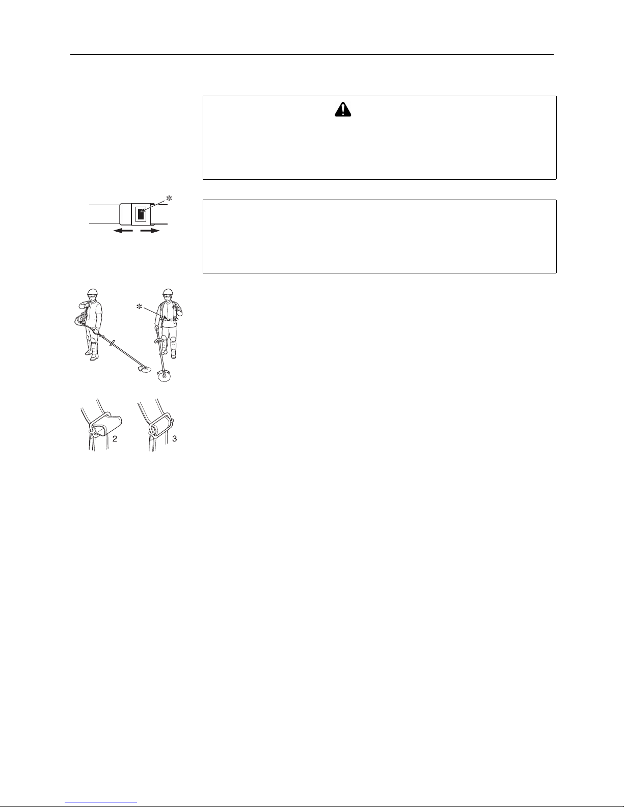
Shoulder harness
∗ Detaching button
Hold the rear handle of the shaft tube in the left hand and hang the right harness on the right
shoulder.
Hold the rear handle of the shaft tube in the right hand and hang the left harness on the left
shoulder.
Fasten the waist belt.
For even load on both sides of the shoulder, joggle the unit on the shoulder a couple of
times.
Adjust the length of the strap to maintain comfortable operation.
Adjust the shoulder straps.
1. Place the brushcutter on your back with the straps loosened.
2. To tighten straps, push the outer strap through the buckle from the top until the loop
formed become approximately the amount of adjustment necessary.
3. While holding the lower outer strap, grasp the buckle and pull upward until the strap is
tight in the buckle.
4. To loosen, reverse this procedure.
WARNING
shindaiwa trimmers and brushcutters are designed to fit a wide variety of body
sizes, but may not be adjustable for extremely tall persons.
Do not use the unit if your feet can reach the cutting attachment.
∗ In case of an emergency, use the detaching button on the harness to free yourself
from the unit.
NOTE
A person's size can affect the balancing adjustment.
Also the balancing procedure may not work with some shindaiwa units on some persons.
If the shoulder harness does not fit you or cannot be adjusted well, please ask your
shindaiwa dealer for assistance.
7
Fuel
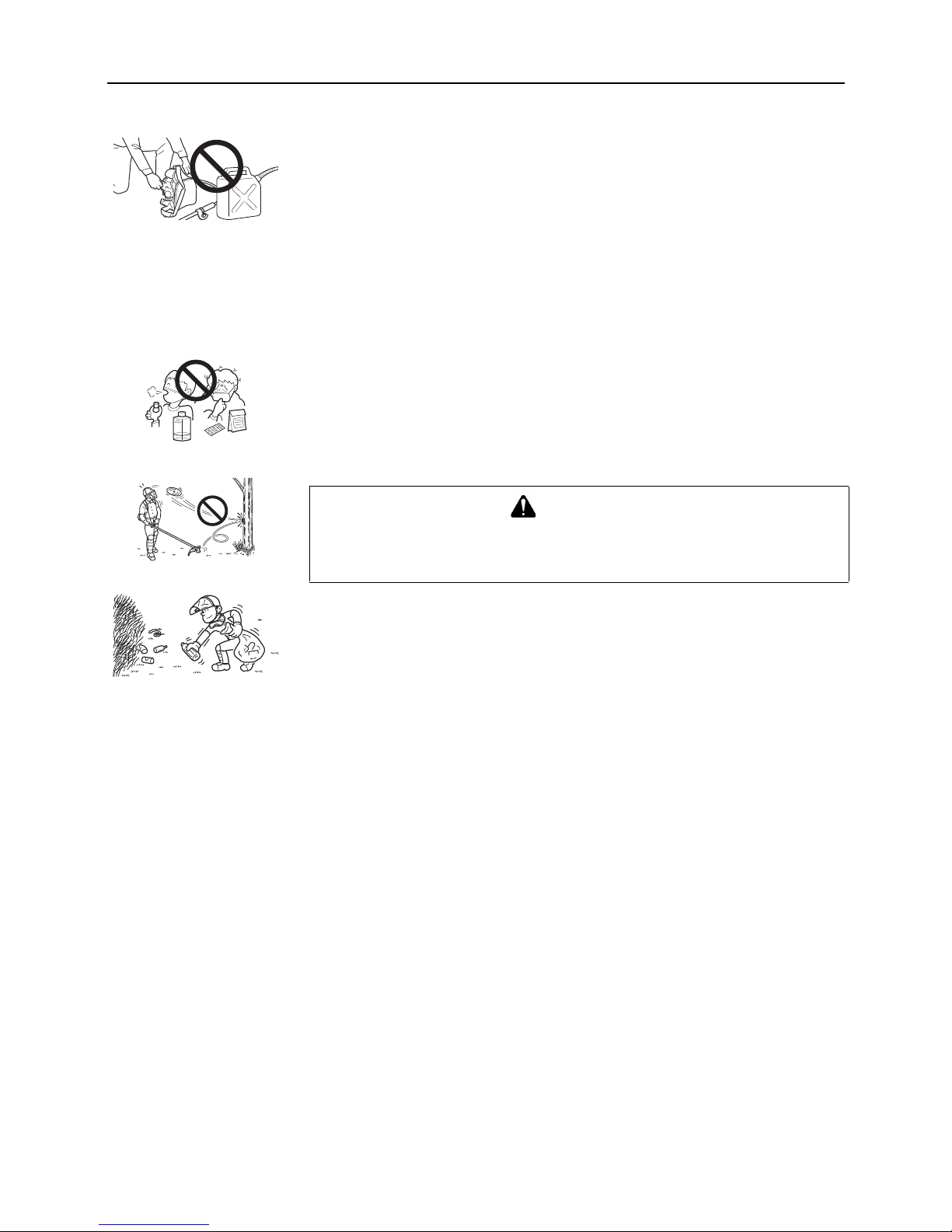
Handle fuel with care.
It is highly flammable.
a) Use an appropriate type of fuel container.
b) Do not smoke or bring flame or sparks near to fuel supplies.
c) The fuel tank may be under pressure.
Always loosen the fuel cap and wait for pressure to be equalized before removing the cap.
d) Fill the fuel tank outdoors over bare ground and install the fuel cap securely.
Do not pour fuel indoors.
e) Wipe any spilled fuel off the unit.
Then move at least 3 m from the fuelling spot before starting the engine.
f) Never refuel while the engine is still hot, or fuel a running engine.
g) Do not store the unit with fuel in its tank, because a fuel leak could start a fire.
Physical condition
You should be in good mental and physical health.
Do not operate if you are under the influence of alcohol or any medication or substance
which could affect your vision, dexterity or judgement.
For your own health and your safe and comfortable work, operate the machine within the
air temperature range of -5ºC to 40ºC.
Area and equipment inspection
Inspect the area before using the unit.
Remove objects the unit could throw.
Remember where there are obstructions to be avoided.
Inspect the unit before using it.
Perform only maintenance or adjustments for which the Operator's Manual gives instruction.
Do not try to repair the unit without proper instruction.
The unit should be serviced only by trained shindaiwa dealer servicemen with the proper
tools.
Be sure that:
a) Engine does not leak fuel.
b) Fasteners are tight, and none are missing.
c) Silencer is in good condition.
d) The unit has the proper equipment-shield, handles, harness, etc.-for the cutting attachment
to be used.
e) If used on the unit, the cutting attachment is properly tightened.
WARNING
Improper fit will result fly off the cutting attachment.
Never start the engine if the power transmission shaft is not in place to prevent the
engine from over speeding or the clutch from flying apart.
8
General operation
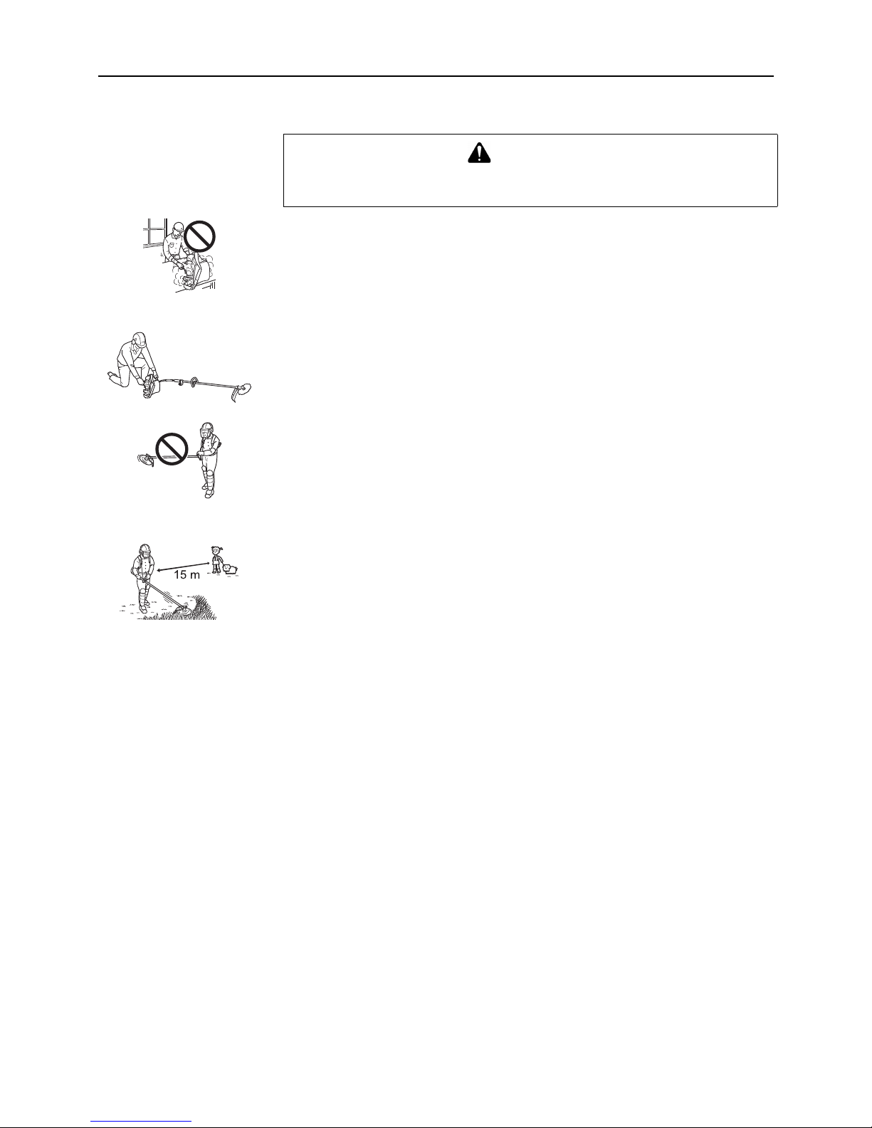
Do not run the engine indoors, or where there is poor ventilation.
Engine fumes contain deadly poisonous carbon monoxide.
Do not operate with a worn or damaged cutting attachment.
Do not run engine at full throttle without a load.
Do not hit rocks, stones, tree stumps, and other foreign objects with the cutting attachment.
If cutting attachment strikes an obstruction, stop engine immediately and inspect cutting
attachment for damage.
Start on ground with cutting attachment in the clear.
Lay the unit down on a clear area and set the controls for starting.
Be sure the cutting attachment cannot contact the ground or any obstruction.
Hold the unit firmly down so you will not lose control during starting.
Do not start the unit in the air, or from the harness.
The unit could swing into your leg or an obstruction if you lose control.
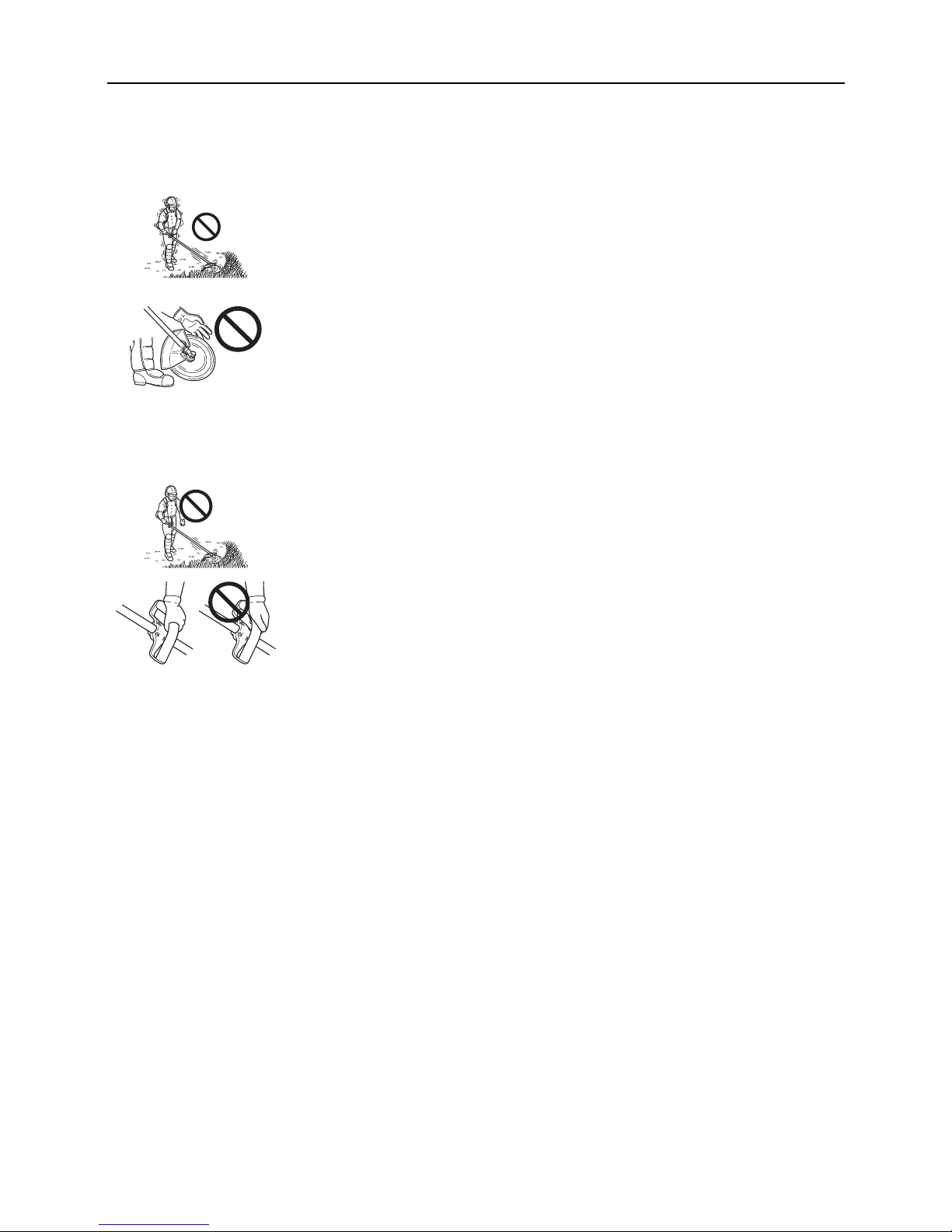
Do not raise the cutting attachment above knee height.
If raised higher, the cutting attachment will be more directly in line with your face.
Thrown objects may hit your face and eyes.
Wear the recommended protectiive gear.
Never operate the unit without the proper guards, shoulder harnes and other protective
devices.
Never operate the unit without good visibility and light.
Do not allow anyone to enter the operating danger zone with you.
The danger zone is an area of 15 m in radius.
Insist that persons in the risk zone beyond the danger zone wear eye protection to protect
them from thrown objects.
If the unit must be used where there are unprotected people, operate at a low throttle speed
to reduce the risk.
Ensure that there are no children, bystanders, and pets in the work area.
Keep all children, bystanders and fellow workers outside 15 m radius for grass trimmers /
brushcutters.
WARNING
Eye protection should be considered for everyone in the zone of risk.
Risk of eye injury diminishes with distance.
9
Stop the engine before leaving the machine, children are not allowed to use the machine, stop
the machine between different working places.
If you are approached, stop the engine and cutting attachment immediately.
Keep your hands and body away from silencer to prevent heat injury while the engine is hot.
Sudden vibration?
Shut down immediately!
Shut down immediately if the unit starts to shake or vibrate.
A sudden vibration is a sign there may be dangerous trouble, such as a broken flywheel, clutch
or cutting attachment, or loose parts.
Do not use the unit until the problem has been properly diagnosed and corrected.
Keep feet and hands away until rotation stops.
When the unit is turned off, make sure the cutting attachment stops before the unit is set down.
If the cutting attachment rotates after throttle is returned to idle, carburettor adjustment is
required.
Follow instruction on this Manual to make the adjustment yourself, or have the carburettor
adjusted by your shindaiwa dealer.
All maintenance and adjustments given in this Manual should be performed by you or your
shindaiwa servicing dealer on a timely basis.
All required service or repair must be done only by shindaiwa servicing dealer.
Never attempt to use an incomplete or one fitted with unauthorized modification.
Do not operate one-handed.
Always use both hands on the handles.
Always hold the unit with the fingers and thumbs encircling the handles.

10
Vibration and cold
It is believed that a condition called Raynaud's Phenomenon, which affects the fingers of
certain individuals, may be brought about by exposure to cold and vibration.
Exposure to cold and vibration may cause tingling and burning followed by loss of color and
numbness in the fingers.
The following precautions are strongly recommended because the minimum exposure which
might trigger the ailment is unknown.
Keep your body warm, especially the head and neck, feet and ankles, and hands and
wrists.
Maintain good blood circulation by performing vigorous arm exercises during frequent work
breaks and also by not smoking.
Limit the number of hours of operation.
Try to fill each day with jobs where operating the trimmer or other hand-held power
equipment is not required.
If you experience discomfort, redness and swelling of the fingers, followed by whitening and
loss of feeling, consult your physician before further exposing yourself to cold and vibration.
Repetitive stress injuries
Painful or numb fingers?
See your doctor immediately!
It is believed that over-using the muscles and tendons of the fingers, hands, arms and
shoulders may cause soreness, swelling, numbness, weakness and extreme pain to the
areas just mentioned.
Certain repetitive hand activities may put you at a high risk for developing a repetitive stress
injury (RSI).
To reduce the risk of repetitive stress injury, do the following:
Avoid using your wrist in a bent, extended or twisted position.
Take periodic breaks to minimize repetition and rest your hands.
Reduce the speed and force in which you do the repetitive movement.
Do exercises to strengthen the hand and arm muscles.
See a doctor if you feel tingling, numbness or pain in the fingers, hands, wrists or arms.
The sooner RSI is diagnosed, the more likely permanent nerve and muscle damage can be
prevented.
11
Rules for safe operation with metal blade
Use correct blade
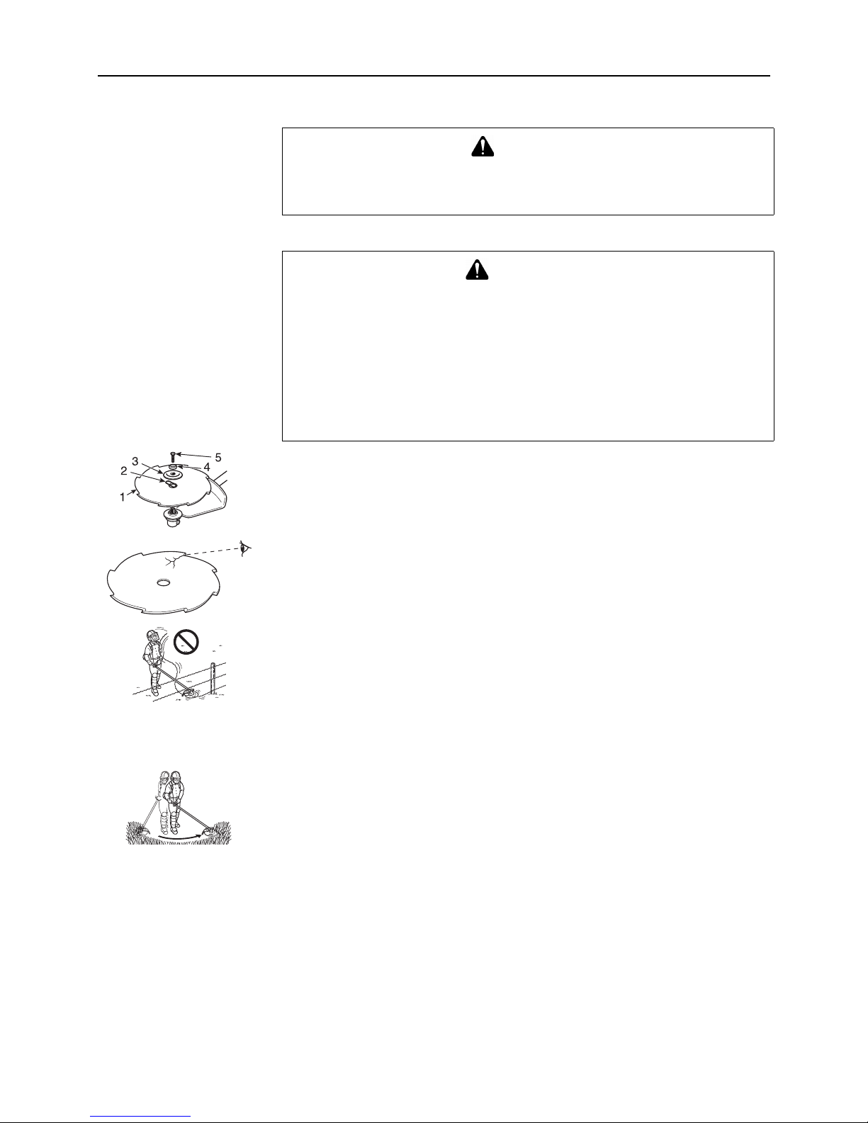
1. Blade. 2. Safety clip. 3. Lower blade retainer. 4. Bolt guard. 5. Bolt.
Inspect blades before use.
Wires can catch and flap around
Always use the blade suited for the job.
Do not hit rocks, stones, tree stumps, and other foreign objects with the blade.
Do not cut into the ground with the blade.
If blade strikes an obstruction, stop engine immediately and inspect blade for damage.
Do not operate with a dull, bent, fractured or discoloured blade and worn or damaged nut.
Do not run engine at full throttle without a load.
Remove all foreign objects from work area.
Do not operate brushcutter without shoulder harness and shield.
Scything weeds
This is cutting by swinging the cutting attachment in a level arc.
It can quickly clear areas of field grass and weeds.
Scything should not be used to cut large, tough weeds or woody growths.
If a sapling or shrub binds the cutting attachment, do not use the cutting attachment as a lever
to free the bind, because this will cause cutting attachment failure.
Instead, shut off the engine and push the sapling or shrub to free the blades.
Do not use a cracked or damaged blade.
DANGER
Always stop the engine when a cutting attachment jam occurs.
Do not attempt to remove an object causing a jam if the engine is running.
Injury can occur if a jam is removed and the cutting attachment suddenly starts.
WARNING
Serious injury may result from the improper use of blades.
Read and comply with all safety instructions listed in this Manual.
The metal blade is designed especially to cut weeds and grass.
To avoid injury due to kickback or blade fracture, do not use the metal blade to cut
brush or trees.
Use only cutting attachments recommended by shindaiwa.
Pieces from a cracked metal blade can fly off during operation.
Inspect metal blades for cracks before each use.
Discard cracked blades no matter how small the crack.
Cracked blades can be the result of misuse or improper sharpening.
12
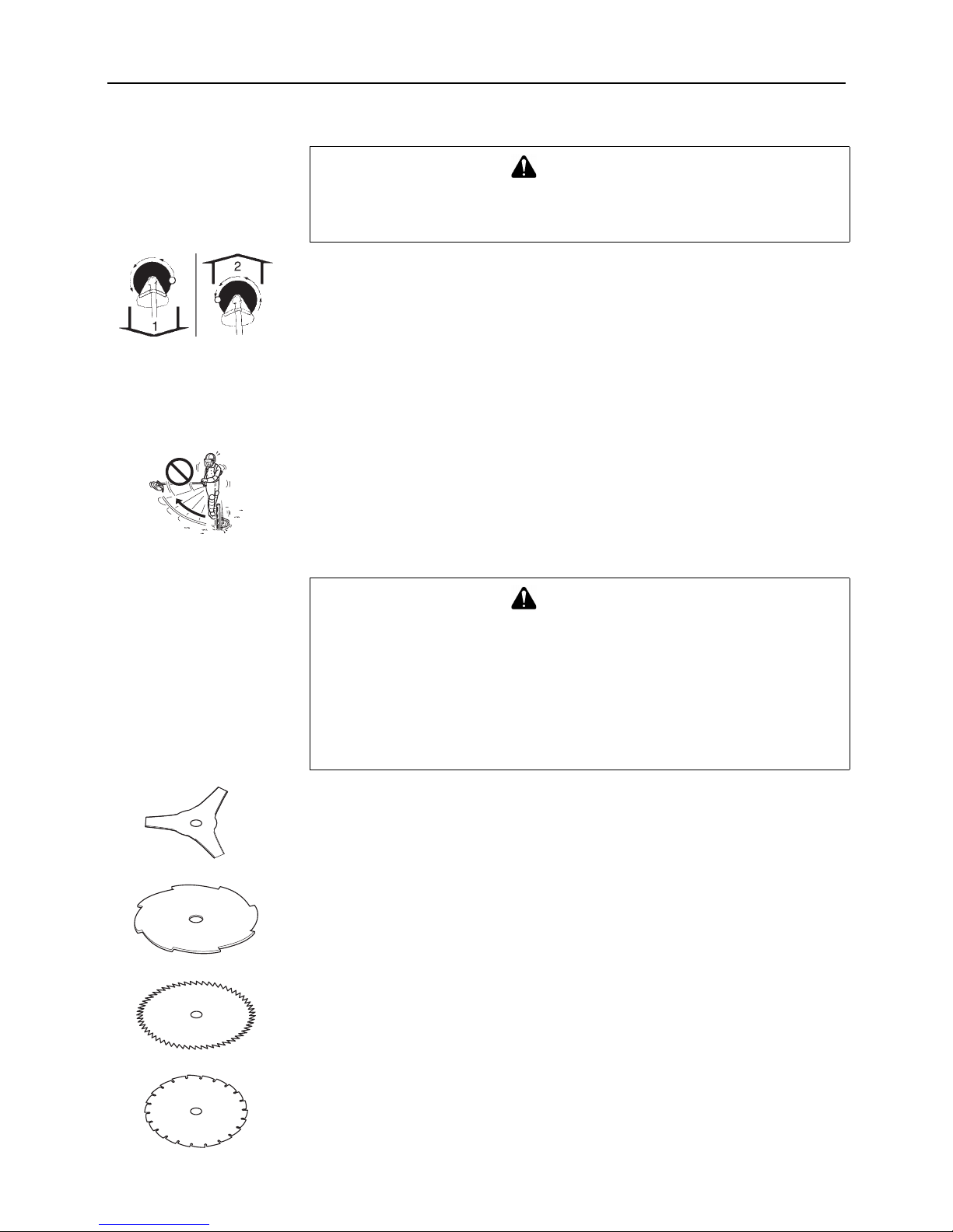
Reaction forces
1. Push
The operator may feel the unit push toward him when he tries to cut the object on right.
If he cannot hold the blade in the cut, a kickback may occur when the blade is pushed out to
where the teeth at the outside furthest point from the operator are cutting.
The blade will "kickback" sideways.
2. Pull
The opposite of push.
When object on left, the operator may feel the unit pull away.
Although this pull type of cutting may cause sawdust to be thrown back at the operator, it is
recommended for sawing off heavy brush because the cutting is smoother and more stable
than when the unit pushes.
Kickback
This may occur when the moving blade at the front of the blade circle contacts strong brush or
trees.
The force that occurs pushes the entire unit and blade violently away in an arc.
Kickback is a danger to a bystander and also a jolting force to the operator.
Blade selection
Plastic grass / weed blade may be used wherever the nylon line head is used.
Do not use this blade for heavy weeds or brush!
8 tooth weed / grass blade is designed for grass, garden debris and thick weeds.
Do not use this blade for brush or heavy woody growth, 2 cm diameter or larger.
80 tooth brush blade is designed for cutting brush and woody growth up to 2 cm diameter.
22 tooth clearing blade is designed for dense thickets and saplings up to 6.5 cm diameter.
WARNING
Be sure you understand the reaction forces of push and pull, and kickback described
in this Manual, and how these forces may affect your balance in the operation of a
unit.
WARNING
Use only shindaiwa approved attachments.
Serious injury may result form the use of a non-approved attachment combination.
shindaiwa will not be responsible for the failure of cutting devices, attachments or
accessories which have not been tested and approved by shindaiwa.
Read and comply with all safety instructions listed in this manual.
The type of blade used must be matched to the type and size of material cut.
An improper or dull blade can cause serious personal injury.
Blades must be sharp.
Dull blades increase the chance of kick-out and injury to yourself and bystanders.
13
Rules for safe operation with nylon line cutting head
Use correct cutting attachment
Operate the machine with its throttle trigger fully grasped for higher engine speed.
Do not give an excessive load to the spinning cutting head to stop.
In case of cutting the thick grass, cut the grass little by little so as to maintain engine speed.
When the rotation of the cutting head stops during operation, immediately release the
throttle trigger to lower the engine speed, pull the machine away from the grass, and fully
grasp the throttle trigger and rotate the cutting head to continue cutting.
Stop the engine immediately when grass or cord / string like object wound around the
cutting head, and take them off before starting the engine.
The basic cutting actions pictured are: Trimming, scything, scalping and lawn edging.
These actions are as follows:
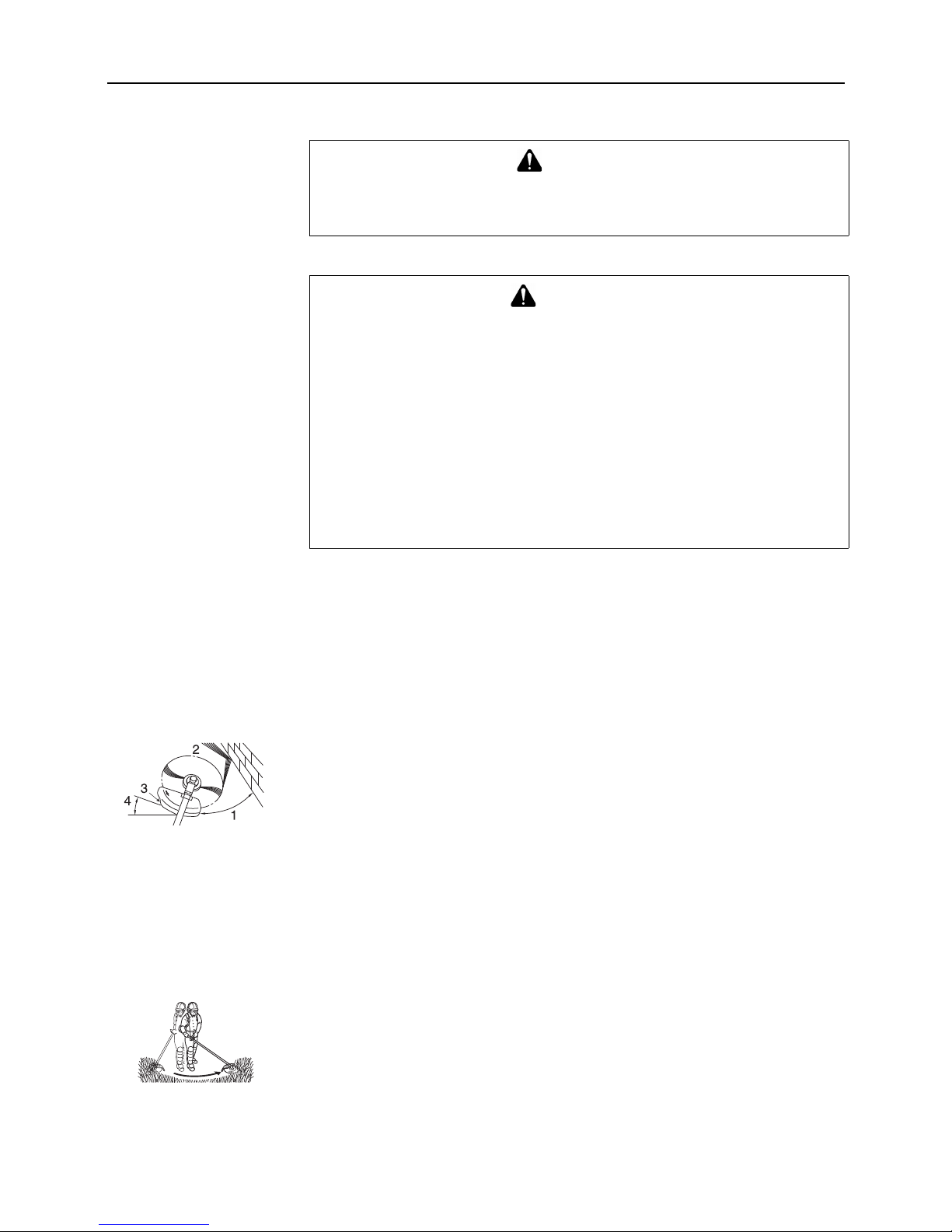
Trimming
1. Angle to wall. 2. Debris. 3. Knife side raised. 4. Angle to ground.
This is feeding the trimmer carefully into the material you wish to cut.
Tilt the head slightly to direct the debris away from you.
If cutting up to a barrier such as a fence, wall or tree, approach from an angle where any debris
ricocheting off the barrier will fly away from you.
Move the line head slowly until the grass is cut right up to the barrier, but do not jam (overfeed)
the line into the barrier.
If trimming up to wire mesh or chain link fencing, be careful to feed only up to the wire.
If you go too far, the line will snap off around the wire.
Trimming can be done to cut through weed stems one at a time.
Place the nylon line cutter near the bottom of the weed never high up, which could cause the
weed to chatter and catch the line.
Rather than cut the weed right through, just use the very end of the line to wear through the
stem slowly.
Scything
This is the cutting or mowing of large grassy areas by sweeping or swinging the trimmer in a
level arc.
Use a smooth, easy motion.
Do not try to hack or chop down the grass.
Tilt the line head to direct the debris away from you on the scything stroke.
Then return without cutting grass for another stroke.
If you are well protected and do not care whether some debris is thrown in your direction, you
may scythe in both directions.
DANGER
Always stop the engine when a cutting attachment jam occurs.
Do not attempt to remove an object causing a jam if the engine is running.
Injury can occur if a jam is removed and the cutting attachment suddenly starts.
WARNING
Serious injury may result from the improper use of cutting attachment.
Read and comply with all safety instructions listed in this Manual.
Use only flexible, non-metallic line recommended by shindaiwa.
Use only cutting attachments recommended by shindaiwa.
Excessive nylon line beyond cut off knife could fly off when the nylon line cutter
starts rotating after adjustment of nylon line length.
Use extreme caution when operating over bare spots and gravel, because the line
can throw small rock particles at high speeds.
The shield on the unit cannot stop objects which bounce or ricochet off hard
surfaces.
Do not trim in any area where there are broken strands of fencing wire.
Remove the broken pieces of wire, or give the area wide berth.
Wear proper safety protection.
Do not cut where you cannot see what the cutting device is cutting.

14
Scalping and edging
Both of these are done with the line head tilted at a steep angle.
Scalping is removing top growth, leaving the earth bare.
Edging is trimming the grass back where it has spread over a pavement or driveway.
During both edging and scalping, hold the unit at a steep angle in a position where the debris,
and any dislodged dirt and stone, will not come back towards you even if it ricochets off the
hard surface.
Although the pictures show how to edge and scalp, every operator must find for himself the
angles which suit his body size and cutting situation.
Nylon line head or disc rotates anticlockwise.
The knife will be on the left side of the shield.
1. Cut on this side. 2. Debris.
For nearly all cutting, it is good to tilt the nylon cutter so that contact is made on the part of line
circle where the line is moving away from you and the shield (See appropriate picture).
This results in the debris being thrown away from you.
Tilting the head to the wrong side will shoot the debris toward you.
If the nylon line cutter is held flat to the ground so that cutting occurs on the whole line circle,
debris will be thrown at you, drag will slow the engine, and you will use up a lot of line.
Do not trim near cars or pedestrians.
Always wear proper eye protection against thrown objects.
Objects can bounce up at you from the ground under the shield, or ricochet off any nearby hard
surface.
Do not trim at high speed near roadways when there is traffic, or in places where there are
pedestrians.
If you must trim where people are in the zone of risk use a much lower or reduced speed, by
using a partial trigger setting.
Do not use full throttle.
Line pushed into wire fencing will snap off.
Do not push the line into tough weeds, trees, or wire fences.
Pushing the line into chicken wire, chain link fencing or thick brush can result in snapped-off
line ends being hurled back at the operator.
The proper way is to cut right up to a barrier, such as any of those mentioned, but never run
the line into or through the obstruction.
Do not cut closely to obstruction or barrier.
Avoid wire.
Avoid nylon line contact with broken wire fencing.
Pieces of wire broken off by the trimmer can be hurled at high speeds.
15
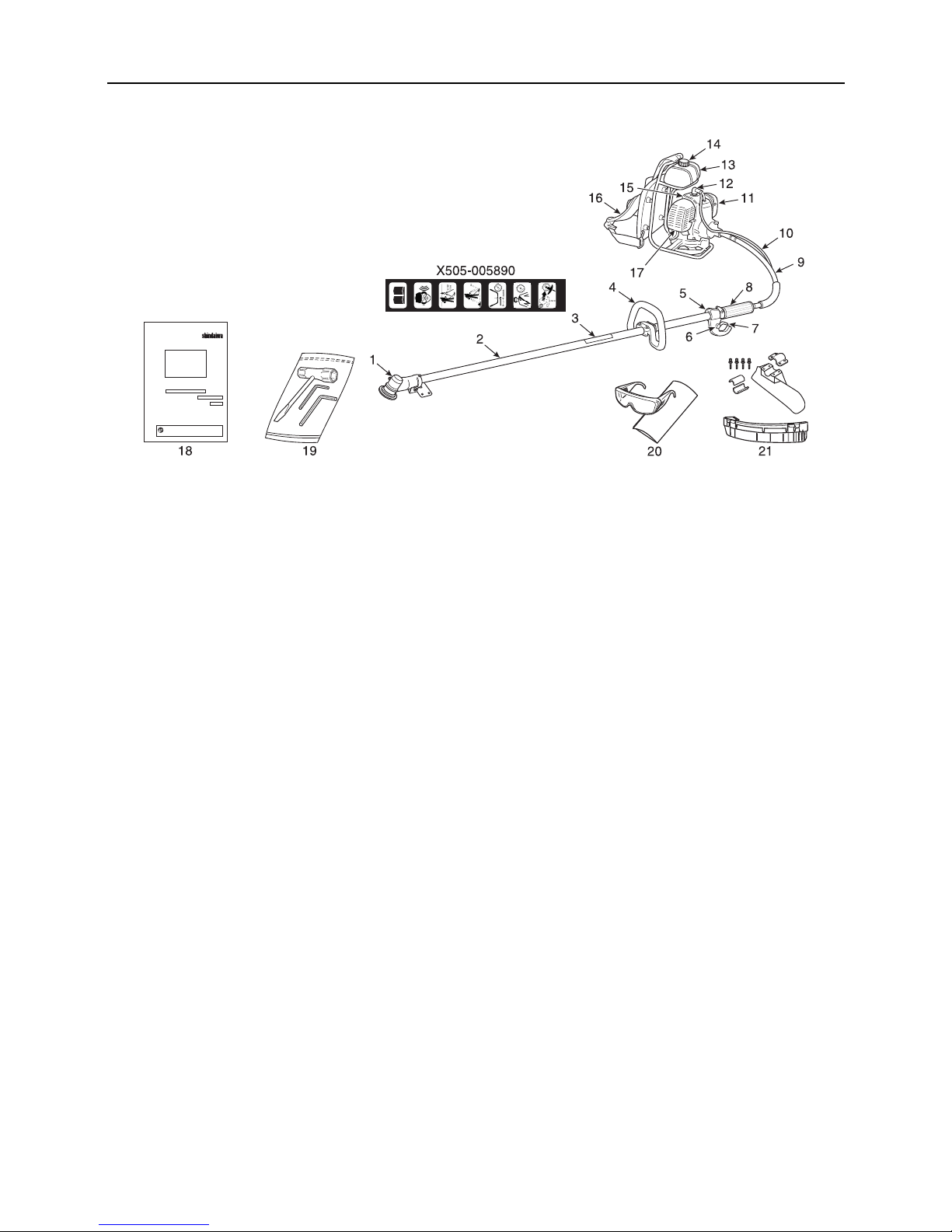
Description
1. Angle transmission - Having two gears to change the
angle of rotating axis.
2. Shaft tube - Part of the unit that provides a casing for
power transmission shaft.
3. Safety decal - Part number X505-005890
4. Front handle - Handle located towards the cutting
device.
5. Ignition switch - Device for connecting and
disconnecting the ignition system and thus allowing the
engine to be started or stopped.
6. Throttle latch - Device for temporality setting the throttle
in a partially open position to aid starting.
7. Throttle trigger - Activated by the operator's finger for
controlling the engine speed.
8. Rear handle - Handle located towards the knapsack
power unit.
9. Flexible shaft assembly - Flexible tube for the power
transmission shaft.
10. Throttle cable
11. Air cleaner cover - Covers air filter.
12. Spark plug
13. Fuel tank - Contains fuel and fuel filter.
14. Fuel tank cap - For closing the fuel tank.
15. Sylinder cover
16. Shoulder harness - Used to support unit on operator's
back.
17. Silencer cover - Cover the silencer not to make operator
touch to hot surface of silencer.
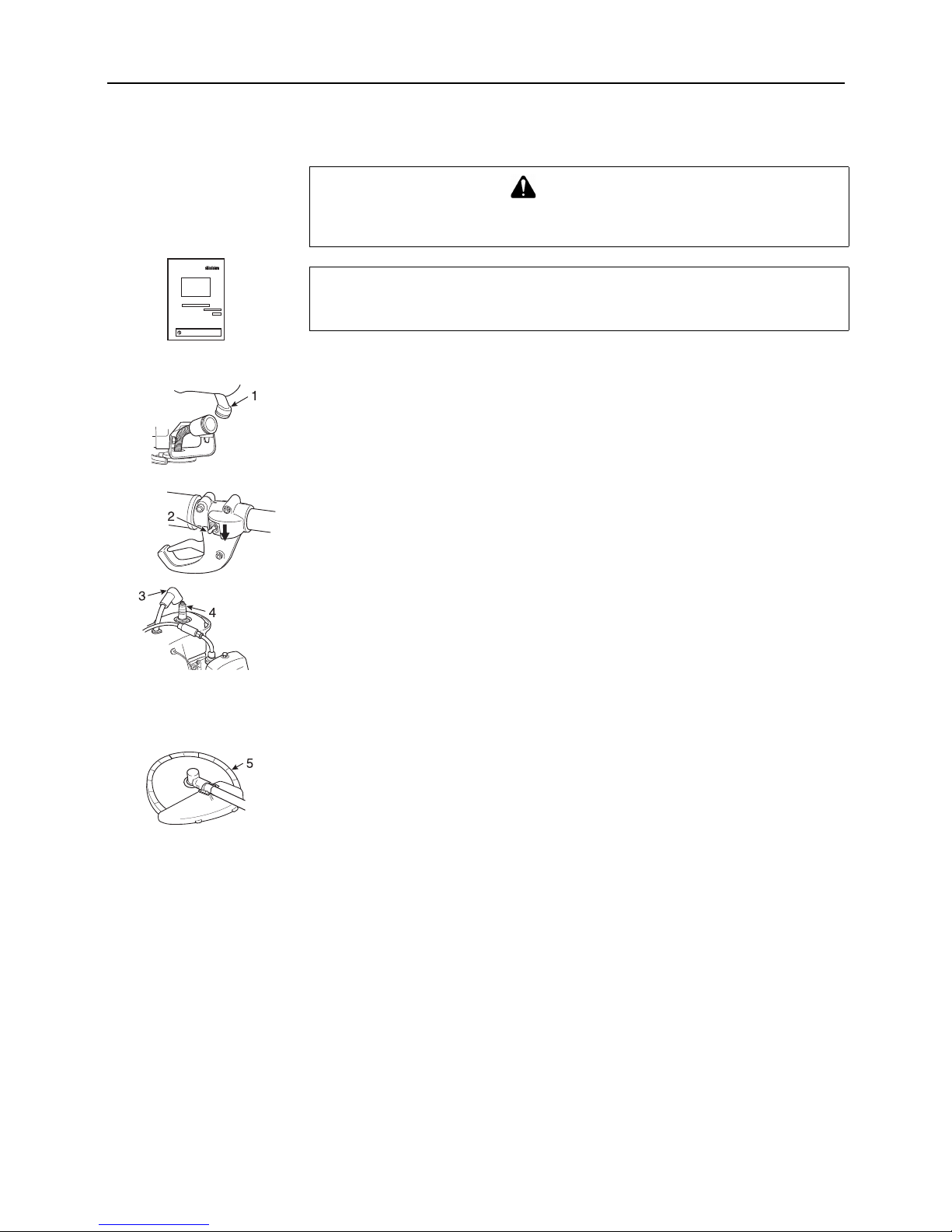
18. Operator's Manual - Included with unit.
Read before operation and keep for future reference to
learn proper, safe operating techniques.
19. Tools - 13 x 19 mm T-wrench (combination screwdriver
/ spark plug socket), 4 mm and 5 mm hexagonal
wrenches.
20. Goggles
21. Shield - Device to protect the operator from accidental
contact with the cutting head and thrown objects.
Shield support and four bolts.
Guard plate - For nylon line head.
Device to protect the operator from accidental contact
with the cutting head and thrown objects.
Cut off knife; Cut nylon line to adjust line length to proper
swath.
16
Assembling
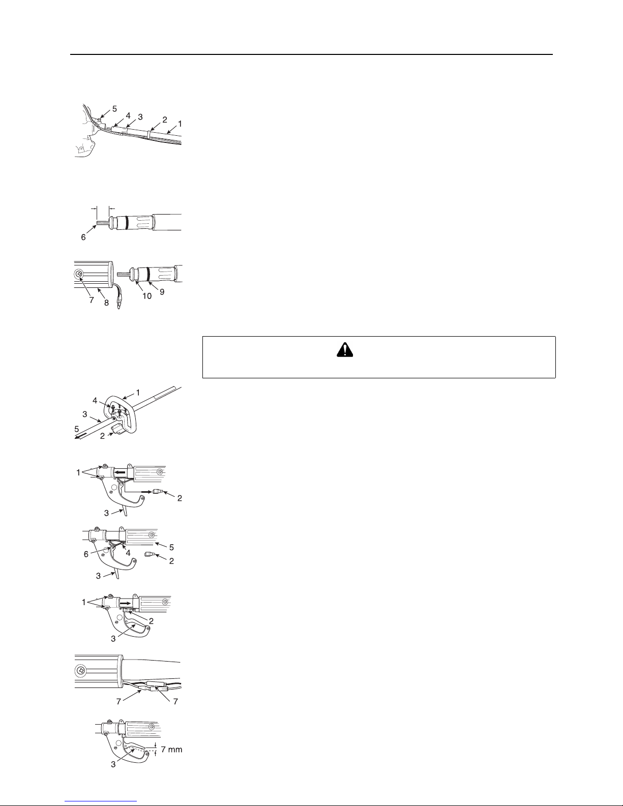
Drive shaft installation
1. Flexible tube. 2. Cable holder 3. Flexible tube housing.
4. Locking hole. 5. Release knob.
Place the engine on a flat surface.
Remove the two covers from the flexible tube.
Route the "engine side" of the flexible tube through the cable holder.
Insert the flexible tube housing into the engine with the locking hole facing up.
Lift up release knob and slide flexible tube housing all the way in until it bottoms in the case
and the release knob locks into the locking hole in the flexible tube housing.
6. Flexible shaft
From the opposite end, rotate and push the flexible shaft to engage it into the clutch drum.
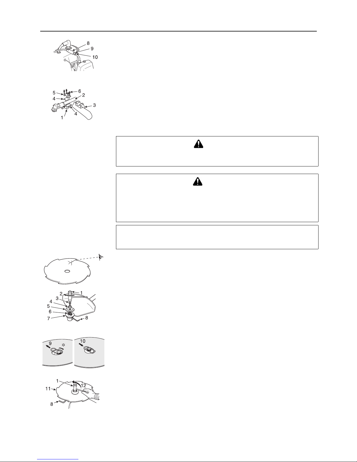
7. Screw (M6 X 8). 8. Rear handle. 9. O-ring. 10. Groove.
Remove the screw (M6 X 8) from the rear handle and slide the O-ring end of the flexible
tube housing into the rear handle until the groove on the housing lines up with the hole for
the screw.
Install and tighten the screw (M6 X 8) firmly.
Loop handle installation
1. Front (Loop) handle. 2. Handle bracket. 3. Shaft tube. 4. Four bolts (M5x25).
5. To engine.
Assemble loop handle and bracket to shaft tube assembly.
Position handle in comfortable operating position and tighten four bolts (M5x25).
Throttle linkage
1. Two screws. 2. Cable guide. 3. Throttle trigger.
Loosen the two screws securing the throttle assembly and slide it forward on the shaft tube.
Remove the cable guide to allow the throttle trigger to swing out.
4. Throttle cable. 5. Rear handle. 6. Wire end.
Slide the throttle cable through the rear handle and insert the wire end into the recess in the
throttle trigger.
Install the cable guide and slide the throttle assembly back into place.
Tighten the two screws securely.
7. Two stop leads
Connect the two stop leads.
Operate the throttle trigger and check for smooth operation.
If any stiffness or binding is noted, the cause must be identified and corrected before the
brushcutter is placed in service.
Test the throttle trigger for proper "free play" of approximately 7 mm in the idle position.
CAUTION
Install the handle so that it does not hide any of the safety decals.
17
8. Adjuster cover. 9. Cable adjuster. 10. Cable locknut.
If necessary, adjustments can be made at the carburettor by:
- Temporarily moving the adjuster cover to expose the cable adjuster.
- Loosening the cable locknut and then screwing the cable adjuster in or out until proper
free play is achieved.
- Tighten cable locknut and move adjuster cover back into place.
Shield installation
1. Bracket. 2. Shaft tube. 3. Shield. 4. Two spacers. 5. Shield support.
6. Four bolts (M5 X 45).
Insert the shield between the shaft tube and the bracket with a spacer.
Fit a spacer and the shield support on the shaft tube and tighten four bolts (M5 X 45) lightly.
Tighten the four bolts firmly.
Installing blade
Inspect blades before installation.
Check for sharpness.
Dull blades increase the risk of blade kickback reactions.
Small cracks can develop into fractures resulting in a piece of blade flying off during operation.
Discard cracked blades no matter how small the crack.
1. Socket wrench. 2. Loosening direction. 3. Bolt. 4. Bolt guard.
5. Lower blade retainer. 6. Safety clip. 7. Blade retainer.
8. Locking tool (4 mm hexagonal wrench).
Align locking hole in blade retainer with notch at the edge of angle transmission and insert
locking tool.
The bolt has a left hand thread and can be removed by turning clockwise.
Remove the bolt guard and lower blade retainer.
9. Safety clip off-centre. 10. Centre the safety clip.
∗ Slip the blade in place.
Slide the safety clip as shown in the illustration.
Fit the blade over the safety clip on the blade retainer and slide the safety clip back to the
original position.
Insert locking tool further into blade retainer fixing hole to fix output shaft.
11. Blade. 12. Tightening direction.
Tighten the bolt (turn anticlockwise) using a socket wrench.
Never fasten applying your too much pressure.
Otherwise the thread of bolt could be broken.
Remove locking tool.
DANGER
If worn bolt and bolt guard for blade are used, there is a danger of blade getting loose.
Replace them with new ones.
CAUTION
Fasten output shaft using locking tool securely in order to avoid the possibility of
output shaft rotating when mounting cutting blade which will prevent the cutting
blade fastening bolt from being tightened sufficiently.
Wear gloves to reduce the risk of injury caused by unintentional contact with the
blade.
NOTE
Check to be sure the locking tool is fully engaged to prevent the output shaft from turning.
18
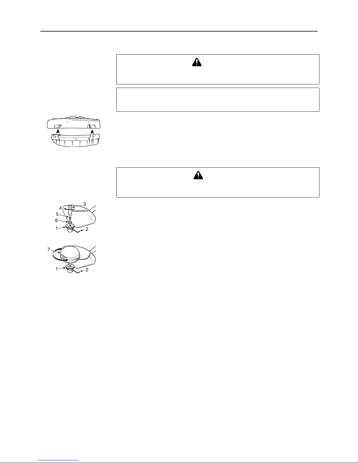
Guard plate installation
(For nylon line operation)
Attach the guard plate to the shield.
Nylon line head installation
(Use with guard plate)
1. Blade retainer. 2. Locking tool (4 mm hexagonal wrench). 3. Socket wrench.
4. Loosing direction. 5. Bolt. 6. Bolt guard.
Align locking hole in blade retainer with notch at the edge of angle transmission and insert
locking tool.
The bolt has a left hand thread and can be removed by turning clockwise.
Remove the bolt guard.
7. Nylon line head
Mount line head to output shaft by turning it anticlockwise until head is tight against blade
retainer.
Remove locking tool.
WARNING
The cut off knife on the debris shield has sharp edges.
Avoid contact when installing or removing the line head.
NOTE
Make sure the guard plate is completely hooked at the hook receiver.
CAUTION
Fasten output shaft using locking tool securely in order to avoid the possibility of
output shaft rotating when mounting nylon line head.
19
Fuel
Fuel
Fuel is a mixture of regular grade petrol and an air-cooled 2-stroke engine oil of reputable
brand name.
Minimum 89 Octane unleaded petrol is recommended.
Do not use fuel containing methyl alcohol or more than 10 % of ethyl alcohol.
Recommended mixture ratio; 50 : 1 (2 %) for ISO-L-EGD Standard (ISO/CD 13738), JASO
FC, FD grade and shindaiwa 50 : 1 oil or 25 : 1 (4 %) for JASO FB grade oil.
- Do not mix directly in engine fuel tank.
- Avoid spilling petrol or oil.
Spilled fuel should always be wiped up.
- Handle petrol with care, it is highly inflammable.
- Always store fuel in approved container.
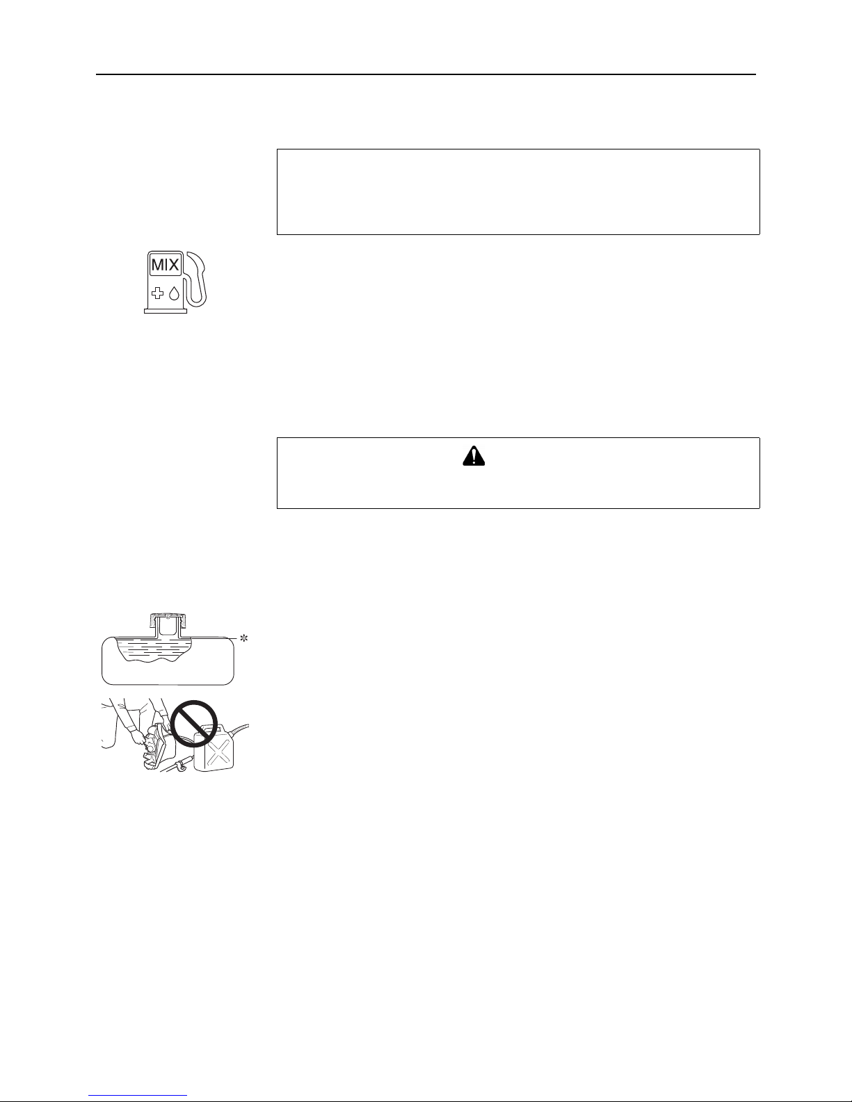
Handling fuel
Never smoke or allow flame or sparks near fuel.
Always fill the fuel tank outdoors.
Never pour fuel indoors.
Always remove the fuel cap slowly to relieve any pressure buildup in the tank.
Never refuel the engine when it is hot or running.
Always use an approved, safe fuel container.
∗ Shoulder level
It is not permitted to fill fuel above the shoulder level of fuel tank.
After fuelling, always wipe away spilled fuel.
Always move at least 3 m away from the fuelling spot before starting the engine.
Never store the unit with fuel in the tank a fuel leak could start a fire.
NOTE
Stored fuel ages.
Do not mix more fuel than you expect to use in thirty (30) days.
Do not mix directly in fuel tank.
DANGER
After refuelling, tighten fuel cap firmly and check for leakage.
In case of fuel leakage, repair before starting operation since there is a danger of fire.

20
Operation
Starting the cold engine
∗ Starter handle
1. Ignition switch. 2. Throttle trigger. 3. Throttle latch.
Before starting engine make sure cutting attachment is not in touch with ground or other
objects.
Lift ignition switch up.
4. Fuel cock. 5. Choke lever.
Open the fuel cock by moving the lever to the down position.
Move choke lever to close ( ) position.
While holding the unit firmly with your left hand, use your right hand to pull the starter handle
slowly upward until you feel the starter engage.
Pull starter handle until first firing sound.
Move choke lever to open ( ) position.
Restart engine and allow to warm up.
When engine is hard to start, use throttle latch.
∗ Pull throttle trigger fully and push throttle latch and release throttle trigger to activate throttle
latch.
After engine starts, pull throttle trigger slightly to release throttle latch immediately.
Starting the warm engine
Lift ignition switch up.
Open the fuel cock by moving the lever to the down position.
Move choke lever to open ( ) position.
If tank is not empty, pull starter handle.
If fuel tank is empty, after refilling, pull starter handle.
WARNING
When engine starts, the cutting attachment may rotate, even with throttle trigger in
low-speed position.
After engine starts, pull throttle trigger slightly to release throttle latch
immediately.
Never use throttle latch for operation.
When engine is started, confirm if there is not any abnormal vibration or sound.
If there is abnormal vibration or sound, ask your dealer to repair.
NOTE
Check unit for loose nuts, bolts and screws before starting.
Always clear work area of debris before starting operation.
Always hold the unit firmly on the ground.
When pulling starter handle, use short pulls, 1/2 to 2/3 of rope length.
Do not allow the starter handle to snap back against the housing.
NOTE
If engine does not start after 4 pulls, use cold starting procedure.
21
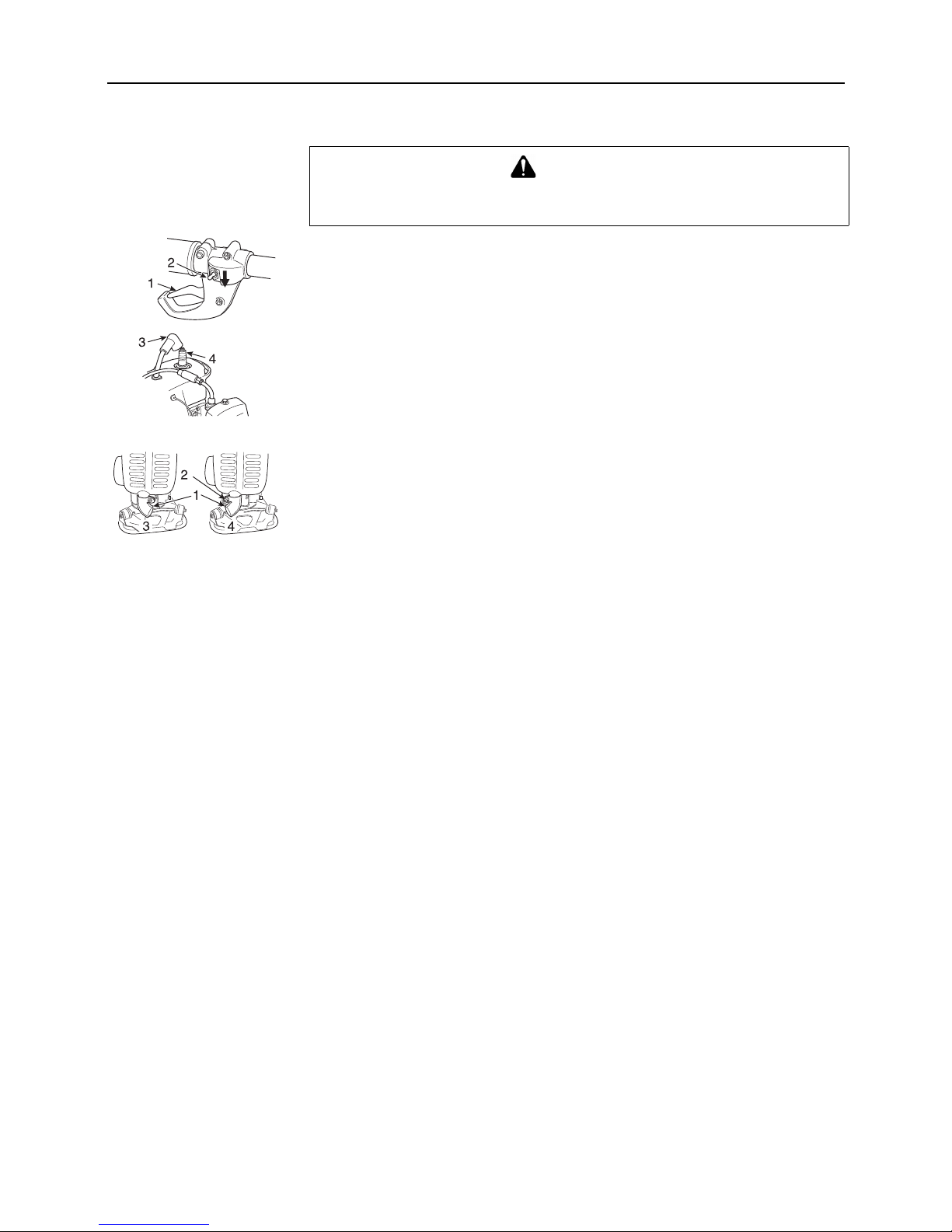
Stopping the engine
1. Throttle trigger. 2. Ignition switch.
Release throttle trigger and allow engine to idle.
Push ignition switch down.
3. Spark plug cap. 4. Spark plug.
Always disconnect the spark plug cap (ignition cable) from the spark plug to ensure the engine
cannot be started before you work on the unit or leave it unattended.
Left hand operation
1. Exhaust guide. 2. Clamp screw (M4 X 10). 3. Right hand operation.
4. Left hand operation.
Some users of the unit may wish to operate the unit left handed.
It is very important to follow these instructions if you wish to do so.
- Loosen the exhaust guide clamp screw (M4 X 10) and rotate the exhaust guide
approximately 90 degrees clockwise as viewed from the top of the engine.
- Tighten the clamp screw (M4 X 10) firmly to prevent the exhaust guide from moving out
of position.
- Put unit on, and in the operating position, check exhaust guide to make sure exhaust flow
is out and to the side of the operator.
Readjust if necessary.
WARNING
If engine does not stop, close choke to stall engine.
Have your shindaiwa dealer inspect and repair ignition switch before using the unit.

22
Service maintenance guide
Area Maintenance Page Before use Monthly
Air filter Clean / Replace 24 •
Fuel system Inspect 24 •
Fuel filter Inspect / Clean / Replace 24 •
Spark plug Inspect / Clean / Adjust / Replace 24 •
Cooling system Inspect / Clean 24 •
Carburettor Adjust / Replace and adjust 25 •
Silencer Inspect / Tighten / Clean 25 •
Angle transmission Grease 25 •*
Drive shaft Grease 25 •*
Starter rope Inspect - •
Cut off knife Inspect / Clean - •
Screws, bolts and nuts Inspect, Tighten / Replace - •
IMPORTANT
Time intervals shown are maximum.
Actual use and your experience will determine the frequency of required maintenance.
* Or 50 hours, whichever occurs first.

23
Troubleshooting
Trouble
Cause Remedy
Engine - hard to start
- does not start
Engine
cranks
Fuel at carburettor Not fuel at carburettor Fuel filter clogged
Fuel line clogged
Carburettor
Clean or replace
Clean
Ask your shindaiwa dealer
Fuel at cylinder No fuel at cylinder Carburettor Ask your shindaiwa dealer
Silencer wet with fuel Fuel mixture is too rich Open choke
Clean / replace air filter
Adjust carburettor
Ask your shindaiwa dealer
Spark at end of
plug wire
No spark at end of plug
wire
Ignition switch off
Electrical problem
Turn switch on
Ask your shindaiwa dealer
Spark at plug No spark at plug Spark gap incorrect
Covered with carbon
Fouled with fuel
Spark plug defective
Adjust 0.6 to 0.7 mm
Clean or replace
Clean or replace
Replace plug
Engine
does not
crank
Internal engine problem Ask your shindaiwa dealer
Engine runs Dies or accelerates poorly Air filter dirty
Fuel filter dirty
Fuel vent plugged
Spark plug
Carburettor
Cooling system plugged
Exhaust port / silencer plugged
Clean or replace
Clean or replace
Clean
Clean and adjust / replace
Adjust
Clean
Clean
WARNING
All trimmer service operations, other than items listed in the Operator's Manual, should be performed by competent
service personnel.
Fuel vapors are extremely flammable and may cause fire and / or explosion.
Never test for ignition spark by grounding spark plug near cylinder plug hole, otherwise serious personal injury may
result.

24
Maintenance and care
If you have any questions or problems, please contact your shindaiwa dealer.
Cleaning air filter
1. Three screws. 2. Air cleaner cover. 3. Air filter.
Close choke.
Loosen three screws and remove air cleaner cover first, and then air filter.
Brush dirt from filter or wash it in a suitable cleaner.
Dry it completely before installation.
Reinstall the air filter and air cleaner cover, and then tighten three screws.
Check fuel system
Check before every use.
After refuelling, make sure fuel does not leak or exude from around fuel pipe, fuel grommet
or fuel tank cap.
In case of fuel leakage or exudation there is a danger of fire.
Stop using he machine immediately and request your dealer to inspect or replace.
Replacing fuel filter
1. Fuel tube. 2. Fuel filter.
Drain all the fuel from the fuel tank.
Pull apart the fuel tube at the joint and remove the fuel filter to clean or replace as
necessary.
Check spark plug
∗ Spark plug gap: 0.6 to 0.7 mm
Check plug gap.
Correct gap is 0.6 to 0.7 mm.
Inspect electrode for wear.
Inspect insulator for oil or other deposits.
Replace plug if needed and tighten to 15 - 17 N•m (150 to 170 kgf•cm).
Cooling system maintenance
1. Cylinder fins. 2. Air intake.
Remove dust and dirt from between fins.
Before each use, remove accumulated debris from bottom engine intake grille.
NOTE
If filter is excessive dirty or no longer fits properly, replace it.
IMPORTANT
To maintain proper engine operating temperature, cooling air must pass freely through the
cylinder fin area.
This flow of air carries combustion heat away from the engine.
Overheating and engine seizure can occur when:
Air intakes are blocked, preventing cooling air from reaching the cylinder,
or
Dust and grass build up on the out side of the cylinder.
This build-up insulates the engine and prevents the heat from leaving.
Removal of cooling passage blockages or cleaning of cylinder fins is considered "Normal
Maintenance".
Any resultant failure attributed to lack of maintenance is not warranted.
25
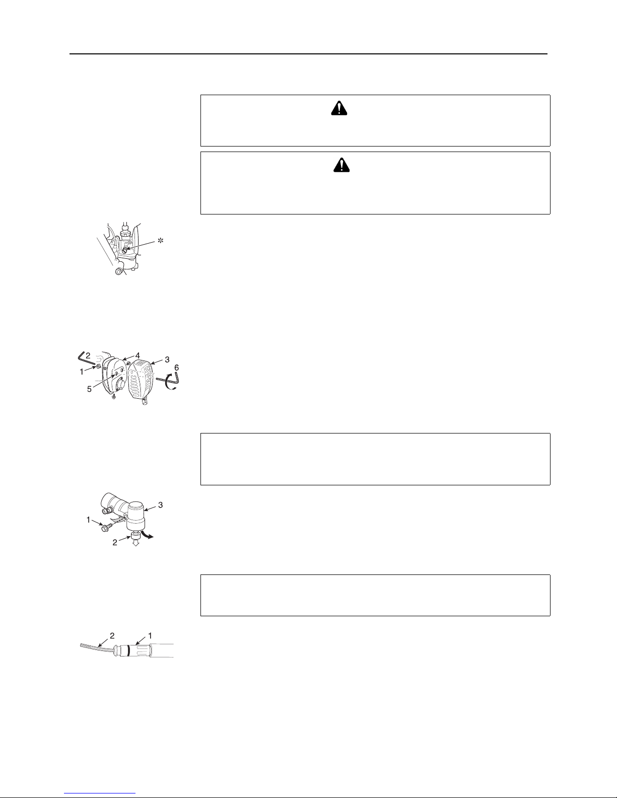
Carburettor adjustment
∗ Idle speed adjuster
Every unit is test run at the factory and the carburettor is fine tuned for maximum performance.
Any change from this setting should be performed only with the aid of an accurate tachometer
(see Specification for r/min setting).
Before adjusting carburettor, clean or replace air filter, start engine and run several minutes to
bring it to operating temperature.
Idle speed adjustment
Turn idle speed adjuster clockwise until cutting attachment begins to turn, then turn screw out
anticlockwise until cutting attachment stops turning.
Turn screw anticlockwise an additional 1/4 turn (2750 r/min).
Cleaning silencer
1. Three bolts (M5 X 10). 2. Hexagonal wrench (4 mm). 3. Silencer cover.
4. Silencer. 5. Two bolts (M6 X 25). 6. Hexagonal wrench (5 mm).
Remove the three bolts retaining the silencer cover and remove the cover.
Clean deposits from silencer and tighten two bolts.
Reinstall the silencer cover and tighten the three bolts securely
Angle transmission
1. Plug (bolt). 2. Collar. 3. Angle transmission.
Remove the plug and the collar from angle transmission.
Add grease, if necessary, using low pressure pump.
Reinstall the collar and the plug.
Lubricating drive shaft (flexible shaft)
1. Flexible tube. 2. Flexible shaft.
Disconnect the flexible tube from the engine.
Pull flexible shaft from the flexible tube, wipe clean and recoat with a thin coating 10 to 20
g, of lithium base grease.
Slide the flexible shaft back in the flexible tube.
Do not get dirt on the flexible shaft.
Install the flexible shaft into the flexible tube, then reconnect the flexible shaft assembly to
the engine.
∗ For maximum shaft life, the flexible shaft should be reversed "end-for-end" during
reinstallation.
WARNING
When carburettor adjustment is completed, cutting attachment should not move at
idle, otherwise serious personal injury may result.
CAUTION
When starting, idle speed adjuster should be adjusted not to rotate the cutting
attachment.
When there is some trouble with the carburettor, contact your dealer.
NOTE
Use good quality lithium multi grease.
Do not overfill housing.
NOTE
Use good quality lithium multi grease.
26
Storage
Long term storage (Over 30 days)
Do not store your unit for a prolonged period of time (30 days of longer) without performing
protective storage maintenance which includes the following:
1. Fuel tube
1) Drain the fuel tank completely.
A. Pull apart the fuel tube at the joint and drain all fuel.
Open fuel cock for fuel drainage.
B. Start the engine and run it at idle speed until it comes to a natural stop.
2) Always store fuel in approved container.
2. Ignition switch
3) Place the ignition switch in the stop position.
4) Remove accumulation of grease, oil, dirt and debris from exterior of unit.
5) Perform all periodic lubrication and services that are required.
6) Tighten all the screws, bolts and nuts.
3. Spark plug cap. 4. Spark plug.
7) Remove the spark plug and pour 10 mL of fresh, clean, two-stroke engine oil into the
cylinder through the spark plug hole.
A. Place a clean cloth over the spark plug hole.
B. Pull the recoil starter handle 2 or 3 times to distribute the oil inside the cylinder.
C. Observe the piston location through the spark plug hole.
Pull the recoil starter handle slowly until the piston reaches the top of its travel and leave
it there.
8) Install the spark plug (Do not connect ignition cable).
5. Blade cover
9) Fit the blade cover onto trimmer blade.
Once the unit is sufficiently cool and dry, wrap the engine section in a plastic bag or other
covering before putting them in storage.
10)Store unit in a dry, dust free place, out of the reach of children and other unauthorized
persons.
WARNING
Do not store in an enclosure where fuel fumes may accumulate or reach an open
flame or spark.
NOTE
For future reference, you should keep this Operator's Manual.

27
Disposal procedure
Dispose of waste oil in accordance with local regulations.
Major plastic parts making up the product have codes showing their materials.
The codes refer to the following materials; dispose of those plastic parts in accordance with
local regulations.
Please contact your shindaiwa dealer in case you do not know how you should dispose of
waste oil / plastic parts.
Mark Material
>PA6-GF< Nylon 6 - Glass fiber
>PP-GF< Polypropylene - Glass fiber
>PE-HD< Polyethylene

28
Specifications
Model
Metal blade Nylon line cutting head
Mass:
Unit without fuel, cutting attachment and shield (ISO11806)
kg 9.7
Volume: Fuel tank L 1.2
Cutting attachment: (0ption)
Blade centre hole diameter
Blade rotational speed at maximum allowable engine speed
Thread
mm
r/min
25.4
10000
Left-handed M8 x 1.25
Gear ratio: Gear ratio and lubrication 1.36 reduction and good quality lithium grease
Rotational direction of output shaft seen from above: Anticlockwise
External dimensions: Length × Width × Height mm - 2820 × 370 × 550
Engine:
Type
Engine displacement
Maximum shaft brake power,
measured in accordance with ISO 8893
Engine speed at maximum engine power
mL (cm
3
)
kW
r/min
Air cooled two stroke single cylinder
33.6
1.24
7500
Recommended maximum engine speed
with standard attachment installed
r/min 11000 -
Recommended engine idling speed
Carburettor
Ignition
Spark plug
Starter
Clutch
r/min 2500
Float type
Flywheel magneto, TCI system
NGK BMR6A
Recoil starter
Automatic centrifugal clutch
Fuel: Regular grade petrol.
Minimum 89 Octane unleaded petrol is recommended.
Do not use fuel containing methyl alcohol or more than
10 % of ethyl alcohol.
Oil
Ratio
Two stroke, air-cooled engine oil.
50 : 1 (2 %) for ISO-L-EGD Standard (ISO/CD13738),
JASO FC, FD grade and shindaiwa 50 : 1 oil or 25 : 1
(4 %) for JASO FB grade oil.
Fuel consumption at maximum engine power
Specific fuel consumption at maximum engine power
L/h
g/(kW•h)
1.14
810
 Loading...