

Shindaiwa BCK-10A Instructions Manual
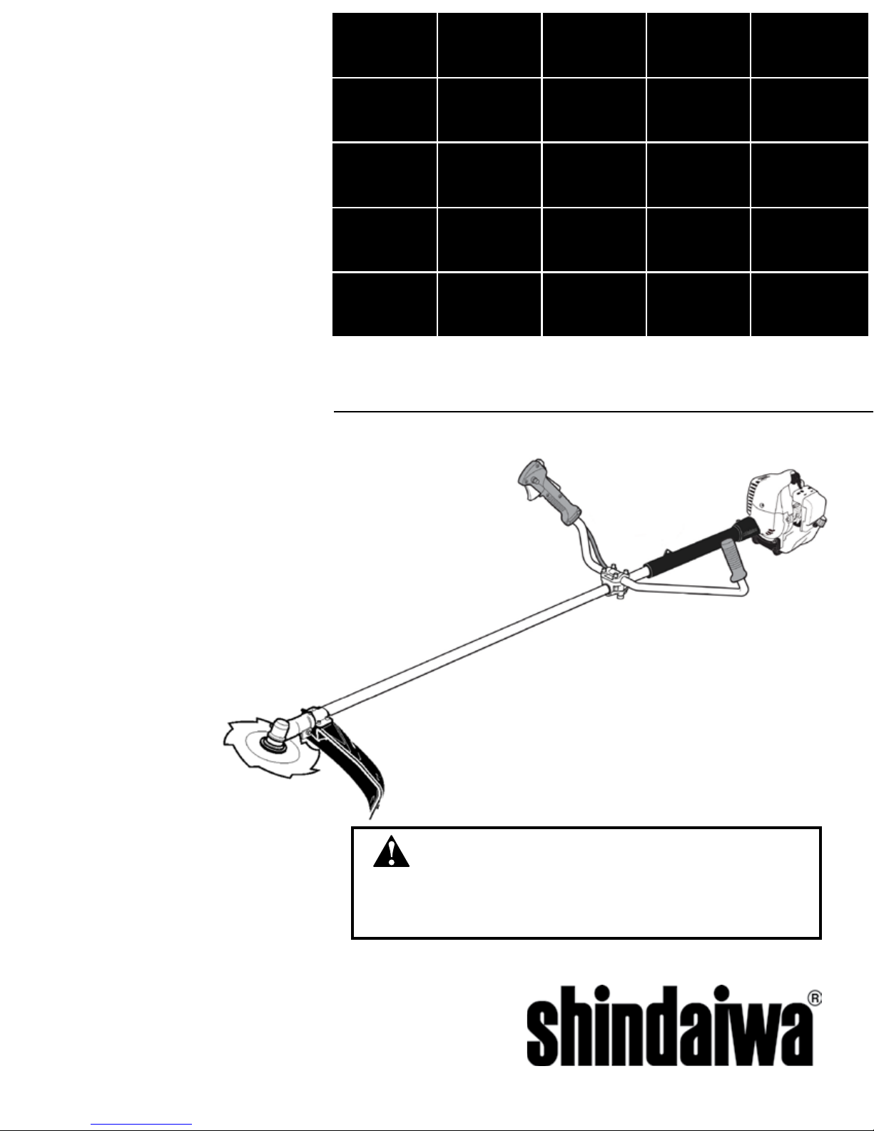
SHINDAIWA GRASS TRIMMER TO BRUSHCUTTER
CONVERSION KIT FOR T242 GRASS TRIMMER
WARNING!
Minimize the risk of injury to yourself and others! Read the Owner's/Operator's manual originally supplied with the unit that is being upgraded and
familiarize yourself with the contents. Always wear eye and hearing protection when operating your unit.
X7502236200
03/12
MODEL: BCK-10A
2
CAUTION!
A statement preceded by the word “CAUTION” contains
information that should be acted upon to prevent mechanical
damage.
IMPORTANT!
A statement preceded by the word “IMPORTANT” is one that
possesses special signicance.
NOTE:
A statement preceded by the word “NOTE” contains information
that is handy to know and may make your job easier.
Throughout this manual are special “attention statements”.
WARNING!
A statement preceded by the triangular attention symbol and the word “WARNING” contains information that should be
acted upon to prevent serious bodily injury.
Attention Statements
Introduction
PAGE
These are instructions to convert a grass trimmer to a blade capable unit. This is not an Owner's/Operator's manual. Information on how to operate and maintain the unit can be found in the Owner's/Operator's manual for the unit you are converting. Note this kit is supplied with a cutting attachment shield that has been redesigned to provide better visibility and a
larger cutting swath when used as a grass trimmer.
Attention Statements ........................2
Safety Labels ....................................3
Contents
IMPORTANT!
The instructions described in this manual are intended to help
you get the most from your Shindaiwa power tool as well as
to protect you and others from harm. These procedures are
guidelines for safe operation under most conditions, and are
not intended to replace any safety rules and/or laws that may
be in force in your area. If you have questions regarding your
Shindaiwa power tool, or if you do not understand something in
these instructions, your Shindaiwa dealer will be glad to assist
you. You may also contact Shindaiwa at the address printed on
the back of this instructional manual.
General Safety Instructions ..............3
Kit Contents ......................................3
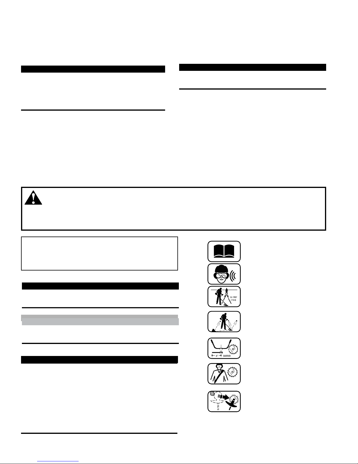
Read and follow this
operators manual.
Failure to do so could
result in serious injury.
Wear eye and hearing
protection at all times
during the operation
of this unit.
Keep bystanders
at least 50 feet (15 m)
away during operation.
Beware of thrown or
ricocheted objects.
Do not operate this unit
with a blade unless the
unit is equipped with a
Shindaiwa-approved
handlebar or barrier.
Always wear a harness
when operating this unit
with a blade. A harness
is also recommended when
using trimmer line.
If unit is used as a
brushcutter, beware of
blade thrust. A jammed
blade can cause the unit
to jerk suddenly and may
cause the operator to
lose control of the unit.
Assembly ..........................................4
Shoulder Strap................................12
Using a Brushcutter Blade ..............13
PAGE PAGE
IMPORTANT!
The information contained in these instructions describes
the product available at the time of publication.
Echo, Inc. reserves the right to make changes to products
without prior notice, and without obligation to make alterations to units previously manufactured.
IMPORTANT!
If the cutting attachment shield has been removed from
your unit or the unit was manufactured prior to October
2001, an additional clamp kit will be required to complete
this installation. The clamp kit required is Shindaiwa part
number 80293.
3
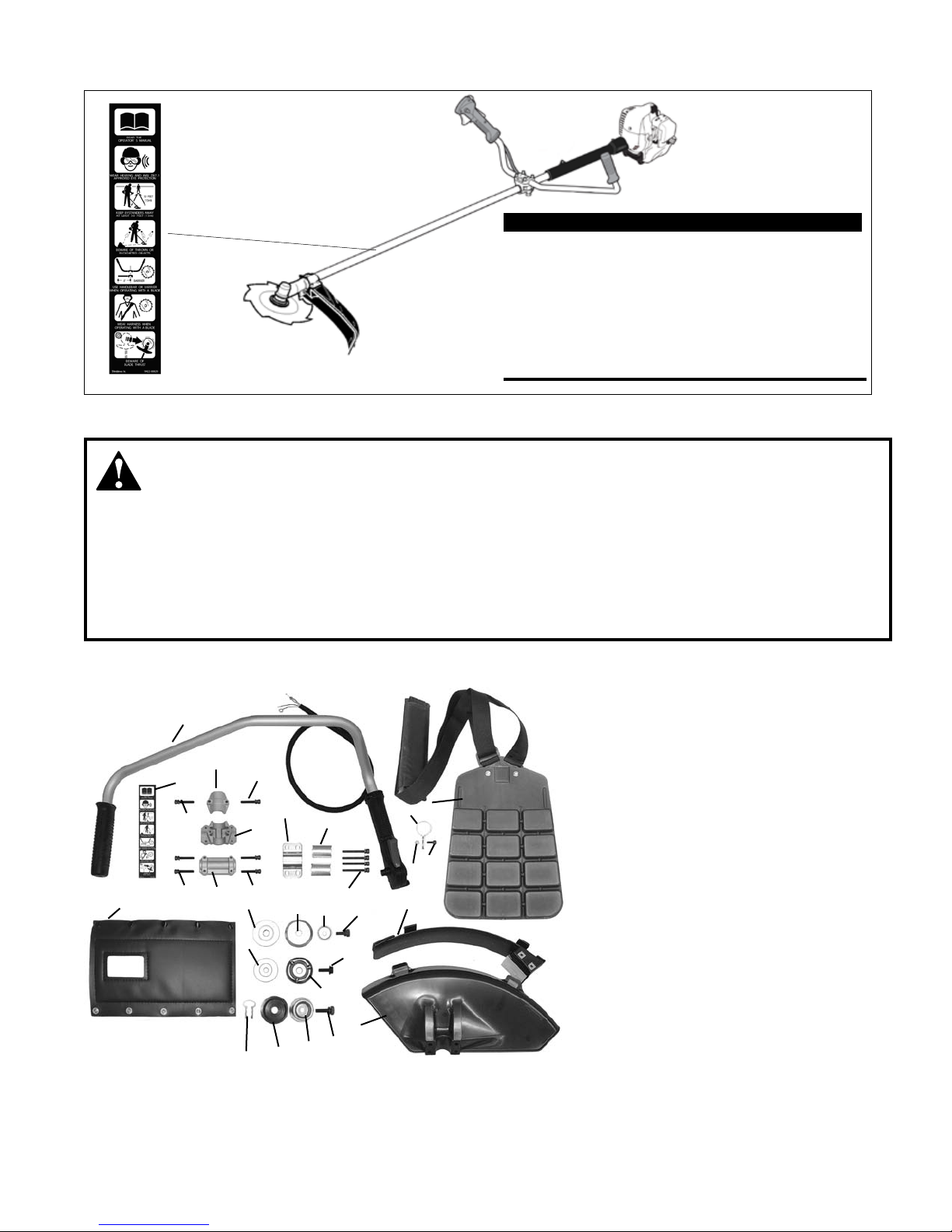
Safety and Operation Information Labels: Make sure
all information labels are undamaged and readable.
Immediately replace damaged or missing information
labels. A new label is provided in this kit and additional
labels are available from your local authorized Shindaiwa dealer. Prior to installing the new label, Remove
old label and clean the outer tube with rubbing alcohol
or similar cleaner.
IMPORTANT!
Safety Labels
■ When operating with a blade, make sure the handle
is positioned to provide you with maximum protection from contacting the blade. Always make sure the
handlebar is installed in accordance with the manufacturers instruction.
■ NEVER use a cracked or warped blade: If a properly
installed blade vibrates, replace it with a new one and
re-check.
WARNING!
■ ALWAYS Shut off the engine immediately if a blade
binds in a cut. Push the branch or tree to ease the
bind and free the blade.
■ Beware of a coasting blade when brushcutting.
A coasting blade can injure while it continues to
spin after the throttle trigger is released or after the
engine is stopped.
General Safety Instructions
# Description Qty
1 Shoulder Strap w/ hip pad 1
2 Hanger 1
3 5mm x 12mm HSH Screw 1
4 5mm Hex Nut 1
5 Handle Bar Assembly 1
6 Caution Label 1
7 Upper Handlebar Cap 1
8 Handlebar Mounting Bracket 1
9 Lower Handlebar Cap 1
10 Hex Soc. Head Bolts, 5mm x 25mm 6
11 5mm x 45mm Bolts 4
12 Debris Shield 1
13 Debris Shield Extension 1
14 Spacer 2
15 Holder (A1) 1
16 Holder (B1) 1
17 Bolt Guard (C1) 1
18 Hex Head Bolt 7mm x 20mm w/
lock washer (D1) 1
19 Hex Head Bolt w/Flat Washer
7 mm x 24 mm (D2) 1
20 Holder/Bolt Guard (B2) 1
21 Holder (A2) (small-36 mm) 1
22 Shaft Cushion 1
23 Upper Clamp 1
24 7 mm x 26 mm Bolt (D3) 1
25 Bolt Guard (C3) 1
26 Holder (B3) 1
27 Clip 1
Assembly Tool (s)
Kit Contents
24
1
2
3
4
6
7
8
9
10
11
14
10
10
10
22
12
13
16
17
18
19
20
21
15
23
5
25
26
27

4
Assembly
Removing the Existing Cutting Attachment Shield
1. Remove the four socket-head cap screws (A), upper
clamp (B), and two shims (C).
2. Remove the cutting attachment shield from the
gearcase.
A
B
C
C
1. Turn the unit over so that the gearcase output shaft faces UP.
Gearcase with noteched ange:
2. Align the hole in the holder with the notch in the gearcase ange, and then
temporarily lock the output shaft by inserting a hex wrench through both
holes.
Gearcase with side-mounted locking hole:
3. Align the notch in trimmer head holder T with the notch in the gear case
ange. Lock the holder and output shaft by inserting a hex wrench through
the locking hole in the gear case and into the aligned notches.
4. While holding the hex wrench turn the trimmer head clockwise to remove.
5. Remove the hex wrench.
6. Remove trimmer head holder (F) or (T).
F
Remove Cutting Attachment
T
5
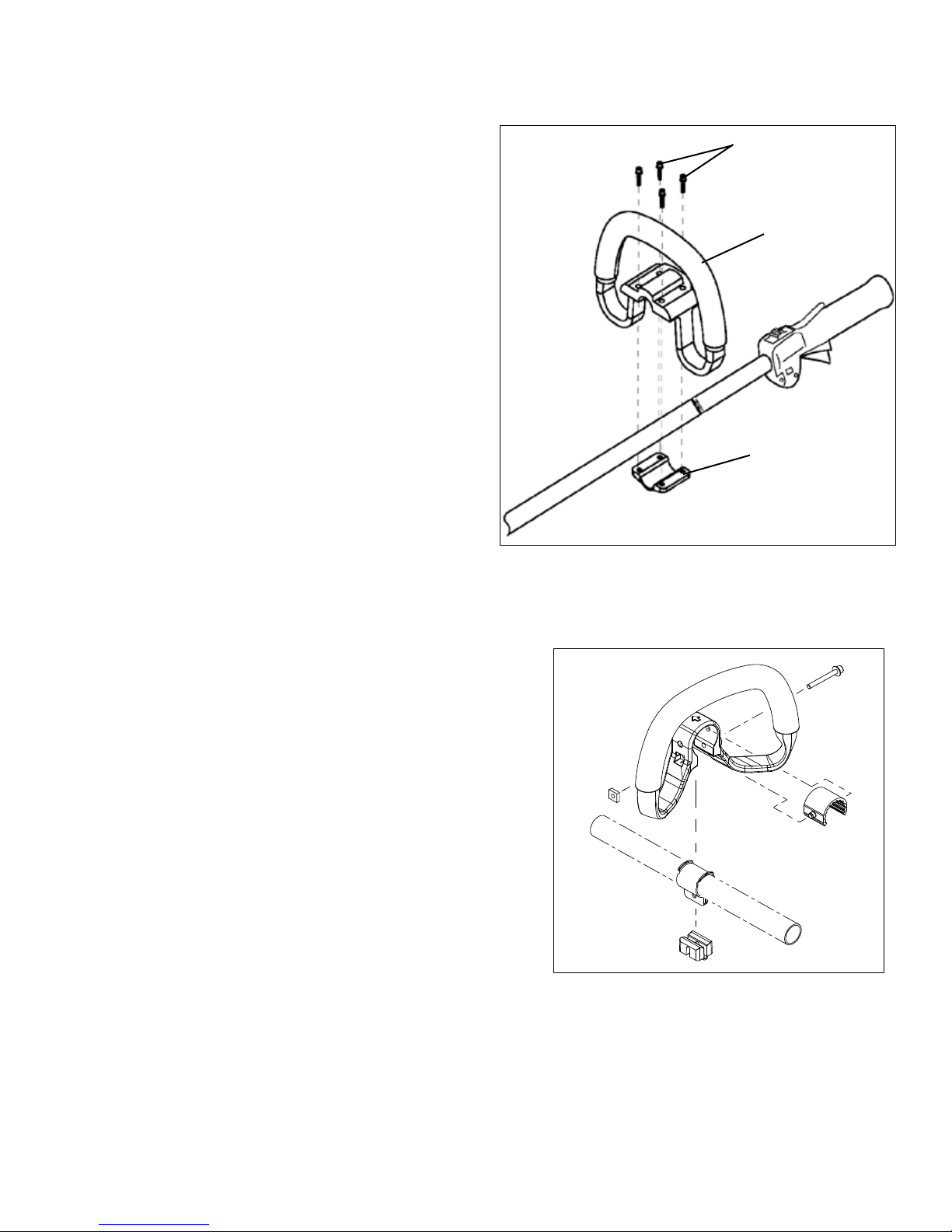
Remove Handle Assembly
1. Remove the four socket-head cap screws (A) on the
handle (B) and remove the handle (B) and mounting
bracket (C).
C
B
A
T242 with 4-screw Handle
T242 with 1-screw Handle
Remove Handle Assembly
1. Remove handle assembly. Retain all parts for
future use.
 Loading...