

Shindaiwa B450 Owner's And Operator's Manual
ENGLISH
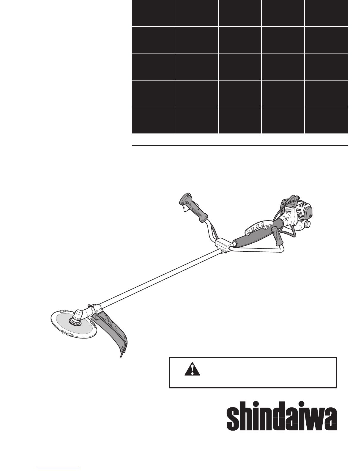
SHINDAIWA OWNER’S/OPERATOR’S MANUAL
B450 BRUSHCUTTER
Part Number 62022-94113 Rev. 5/05
EPA VERSION
Minimize the risk of injury to yourself and others!
Read this manual and familiarize yourself with the
contents. Always wear eye and hearing protection
when operating this unit.
WARNING!
2
Contents
Throughout this manual are special
“Attention Statements”.
IMPORTANT!
The operational procedures described
in this manual are intended to help you
get the most from your unit as well as
to protect you and others from harm.
These procedures are guidelines for safe
operation under most conditions, and are
not intended to replace any safety rules
and/or laws that may be in force in your
area. If you have questions regarding your
B450-series power tool, or if you do not
understand something in this manual, your
Shindaiwa dealer will be glad to assist
you. You may also contact Shindaiwa, Inc.
at the address printed in this Manual.
Attention StatementsIntroduction
PAGE
The Shindaiwa B450 has been designed
and built to deliver superior performance
and reliability without compromise to
quality, comfort, safety or durability.
Shindaiwa engines represent the leading
edge of high-performance engine technol
ogy, delivering exceptionally high power
with remarkably low displacement and
weight. As an owner/operator, you’ll soon
discover for yourself why Shindaiwa is
simply in a class by itself!
IMPORTANT!
The information contained in this
owner's/operator's manual describes
B450 Brushcutters available at the time
of publication.
Shindaiwa Inc. reserves the right to make
changes to products without prior notice,
and without obligation to make alterations
to units previously manufactured.
Attention Statements ...................................2
Safety Information ........................................
2
Safety Labels .................................................4
Product Description .....................................
5
Specifications ................................................
5
Assembly and Adjustments .........................6
Mixing Fuel ................................................13
Starting the Engine ....................................
13
Stopping the Engine ..................................14
Engine Idle Adjustments ...........................15
Checking Unit Condition ..........................15
Using a Brushcutter ..................................
16
Maintenance ...............................................18
Long Term Storage ....................................
20
Troubleshooting Guide .............................
22
Emission System Warranty .......................
23
CAUTION!
A statement preceded by the word
“CAUTION” contains information that
should be acted upon to prevent
mechanical damage.
WARNING!
A statement preceded by the trian
gular attention symbol and the word
“WARNING” contains information that
should be acted upon to prevent serious bodily injury.
Work Safely
Shindaiwa Brushcutters operate at very
high speeds and can do serious damage
or injury if they are misused or abused.
Never allow a person without training
or instruction to operate your B450
Brushcutter!
Stay Alert
You must be physically and mentally fit to
operate this unit safely.
General Safety Instructions
WARNING!
Never operate power
equipment of any kind if you are tired
or if you are under the influence of
alcohol, drugs, medication or any other
substance that could affect your ability
or judgement.
WARNING!
Minimize the Risk of Fire!
NEVER smoke or light fires near the
engine.
ALWAYS
stop the engine and allow it
to cool before refueling. Avoid overfill
ing and wipe off any fuel that may have
spilled.
ALWAYS
inspect the unit for fuel leaks
before each use. During each refill,
check that no fuel leaks from around
the fuel cap and/or fuel tank. If fuel
leaks are evident, stop using the unit
immediately. Fuel leaks must be re
-
paired before using the unit.
ALWAYS
move the unit to a place well
away from a fuel storage area or other
readily flammable materials before
starting the engine.
NEVER place flammable material close
to the engine muffler.
NEVER run the engine without the
spark arrester screen in place.
WARNING!
Never make unauthorized attachment
installations. Do not use attachments
not approved by Shindaiwa for use on
this unit.
WARNING!
The engine exhaust from this product
contains chemicals known to the State
of California to cause cancer, birth
defects or other reproductive harm.
NOTE:
A statement preceded by the word “NOTE”
contains information that is handy to know
and may make your
job easier.
IMPORTANT!
A statement preceded by the word
“IMPORTANT” is one that possesses
special significance.
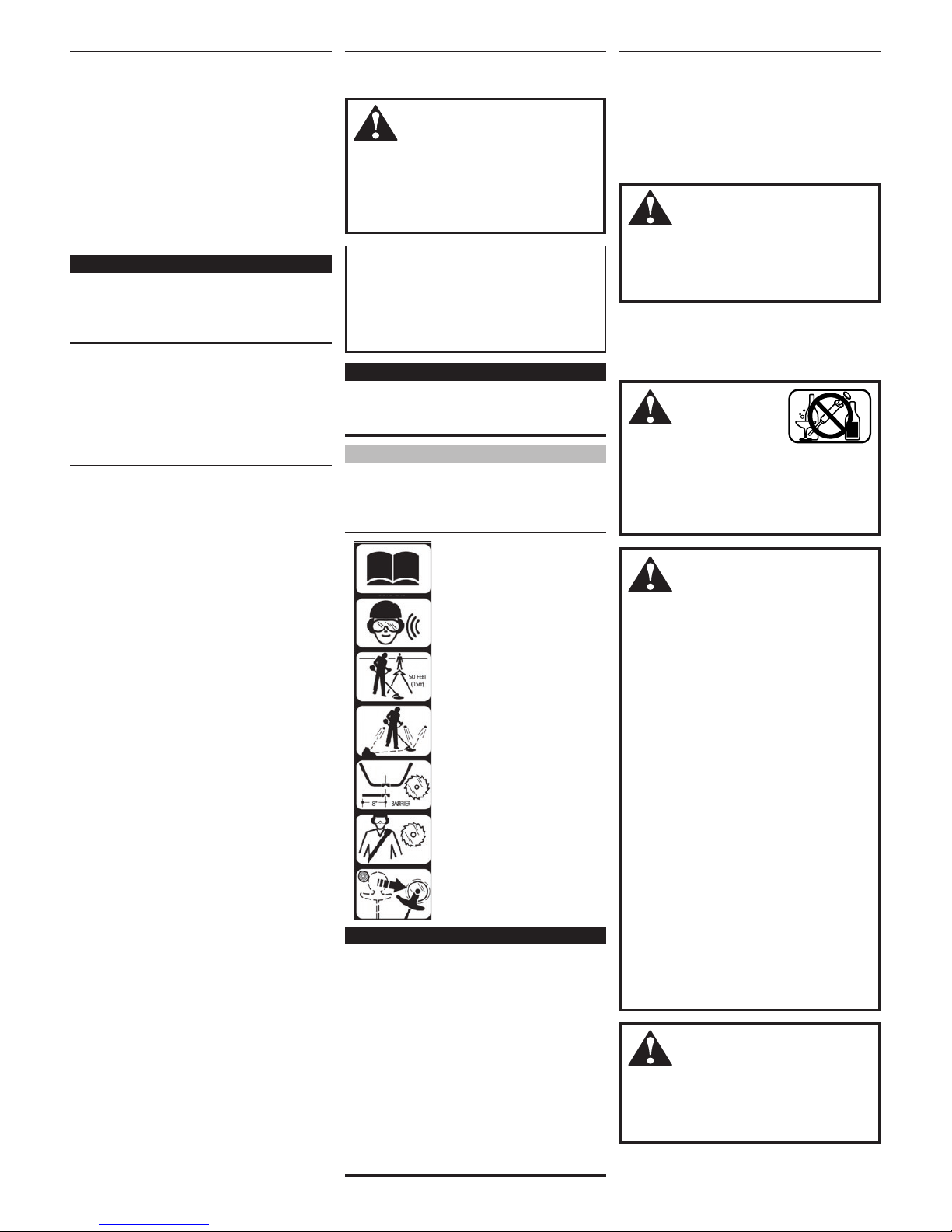
Do not operate this unit
with a blade unless the
unit is equipped with a
Shindaiwa-approved handlebar.
Always wear a harness when
operating this unit with a blade.
a harness is also recommended
when using trimmer line.
Beware of blade thrust. A jammed
blade can cause the brushcutter
to jerk suddenly and may cause
the operator to lose control
of the unit.
Read and follow this
operators manual.
Failure to do so could
result in serious injury.
Wear eye and hearing
protection at all times
during the operation
of this unit.
Keep bystanders
at least 50 feet (15 m)
away during operation.
Beware of thrown or
ricocheted objects.
3
ENGLISH
WARNING!
Use Good Judgment
ALWAYS wear eye protection to shield
against thrown objects.
NEVER run the engine when transport-
ing the unit.
NEVER run the engine indoors! Make
sure there is always good ventilation.
Fumes from engine exhaust can cause
serious injury or death.
ALWAYS
clear your work area of trash
or hidden debris that could be thrown
back at you or toward a bystander.
ALWAYS
use the proper cutting tool for
the job.
ALWAYS
stop the engine immediately
if it suddenly begins to vibrate or shake.
Inspect for broken, missing or improperly installed parts or attachments.
ALWAYS
keep the unit as clean as
practical. Keep it free of loose vegetation, mud, etc.
ALWAYS hold the unit firmly with both
hands when cutting or trimming, and
maintain control at all times.
ALWAYS
keep the handles clean.
ALWAYS
disconnect the spark plug
wire before performing any
maintenance work.
ALWAYS
, if a blade should bind fast in
a cut, shut off the engine immediately.
Push the branch or tree to ease the
bind and free the blade.
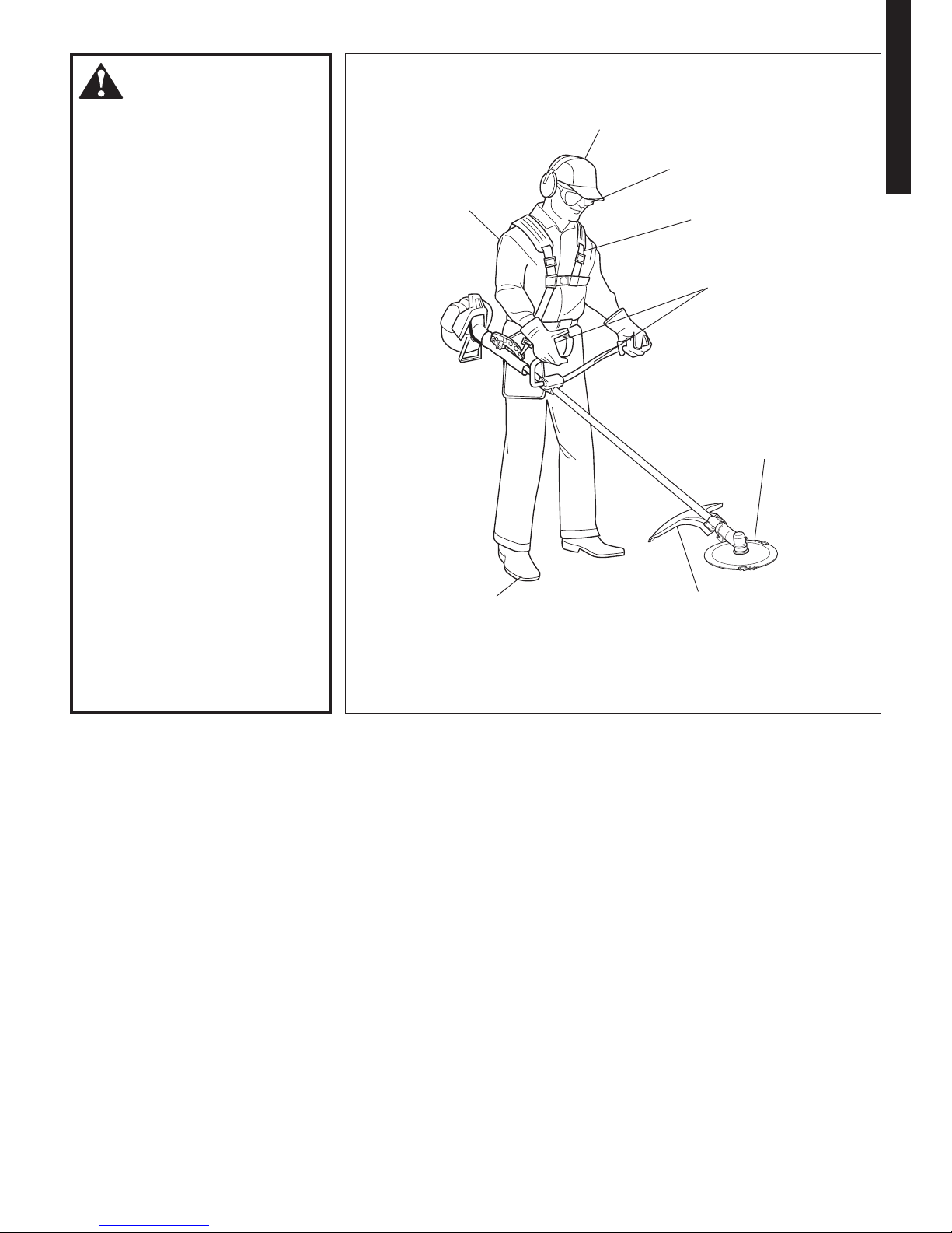
The Properly Equipped Operator
Always operate with
both hands firmly
gripping the unit.
Wear close-fitting clothing to
protect legs and arms. Gloves
offer added protection and are
strongly recommended. Do
not wear clothing or jewelry
that could get caught in
machinery or underbrush.
Secure hair so it is
above shoulder
level. NEVER
wear shorts!
Wear hearing protection
devices and a broad-brimmed
hat or helmet.
Always wear eye protection
such as goggles or safety glasses.
Keep away from the rotating blade
at all times, and never lift a moving
attachment above waist-high.
Wear appropriate footwear (non-skid
boots or shoes): do not wear open-toed
shoes or sandals. Never operate the
unit while barefoot!
Keep a proper
footing and do not
overreach—
maintain your
balance at all times
during operation.
Always make sure
the appropriate
cutting attachment
shield is correctly
installed and in good
condition.
Figure 1
Always wear a harness when operating
a unit equipped with a blade.
General Safety Instructions
4
Safety Labels
Figure 3
IMPORTANT!
Safety and Operation Information Labels:
Make sure all information labels are
undamaged and readable. Immediately
replace damaged or missing information
labels. New labels are available from your
local authorized Shindaiwa dealer.
This label indicates the minimum
distance between front handle and
rear grip per ANSI B175.3.
Be Aware of the Working Environment
Avoid long-term operation
in very hot or very cold
weather.
Make sure bystanders or observers
outside the 50-foot “danger zone”
wear eye protection.
Be extremely careful
of slippery terrain,
especially during rainy
weather.
Always make sure the
appropriate cutting
attachment shield is
correctly installed.
If contact is made with a
hard object, stop the engine
and inspect the cutting
attachment for damage.
When operating in rocky terrain or near
electric wires or fences, use extreme caution to avoid
contacting such items with the cutting attachment.
Be constantly alert for objects and
debris that could be thrown either from
the rotating cutting attachment or
bounced from a hard surface.
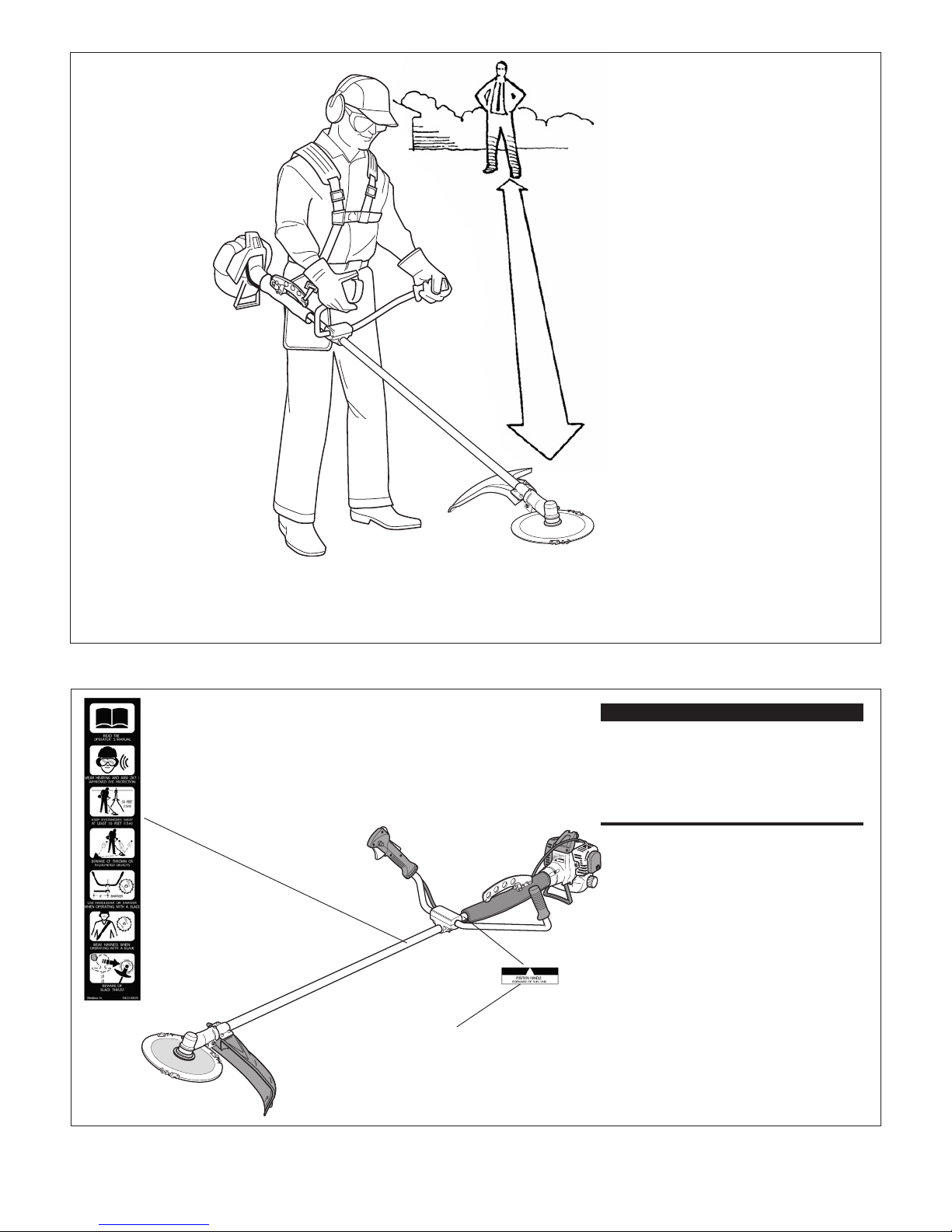
Reduce the risk of
bystanders being struck
by flying debris. Make
sure no one is within 50
feet (15 meters)—that’s
about 16 paces—of an
operating attachment.
Figure 2
50
FEET
B450
5
ENGLISH
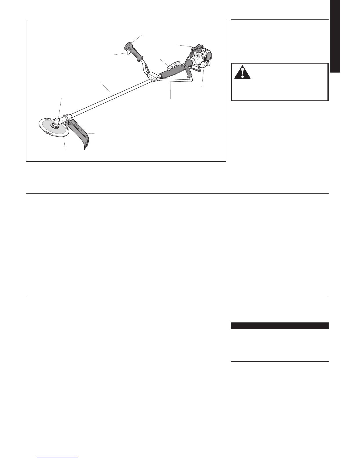
Throttle Trigger
Gearcase
Brushcutter Blade
Outer Tube
Handlebar
Fuel Tank
Cylinder
Cover
Cutting
Attachment
Shield
Hanger
Ignition
Switch
Product Description
B450 BRUSHCUTTER
Using the accompanying illustrations as a
guide, familiarize yourself with your unit
and its various components. See Figure 4.
Understanding your unit helps ensure top
performance, long service life, and safer
operation.
Figure 4
Specifications
Prior to Assembly
Before assembling this product, make sure
you have all the components required for a
complete unit.
Engine assembly (powerhead).
Outer tube assembly.
Cutting attachment shield.
Double shoulder harness.
Hip protector.
Specifications are subject to change without notice.
IMPORTANT!
The terms “left,” “left-hand,” and “LH”;
“right,” “right-hand,” and “RH”; “front” and
“rear” refer to directions as viewed by the
operator during normal operation of this
product.
Cutting attachment (trimmer head or
brushcutter blade).
Tool kit, which includes 3mm, 4mm,
and 5mm “L” type hexagonal wrenches,
8mm/l0mm open-end wrench and com
-
bination spark plug/tool.
Components required for assembly
(cable ties, throttle cable holder, etc.).
Carefully inspect all components
for damage.
WARNING!
Do not make unauthorized modifica
tions or alterations to this unit or its
components.
B450 Dry Weight (less attachments) .......................
17.9 lb./ 8.1 kg
Engine Model ...............................................................................S450
Engine Type ............................ 2-cycle, vertical cylinder, air cooled
Bore x Stroke .............................................................. 40mm x 33mm
Displacement ...........................................................2.5 cu. in./41.5cc
Maximum Power ................... 2.3 HP (1.7 kw) @ 7500 RPM (min-1)
Fuel/oil Ratio ....................................Gasoline-oil mixture, 50:1 with
Shindaiwa Premium 2-cycle Mixing Oil
Carburetor Type ..........................
TK sliding valve, diaphragm type
Fuel Tank Capacity ....................................................
34 oz./1000 ml
Ignition ..................................Fully electronic, transistor controlled
Spark Plug ....................................................................Champion CJ8
Air Cleaner Type .........................................................
Foam element
Starting Method ............................................................Recoil starter
Stopping Method .................................Slide switch, grounding type
Handle ............................................................Barrier type handlebar
Transmission Type ............................
Automatic, centrifugal clutch
through bevel gear
Included Accessories ............................. Cutting attachment shield,
double shoulder harness, toolkit
EPA Emission Compliance Period* ............................... Category A
* The EPA emission compliance referred to on the emission compliance
label located on the engine, indicates the number of operating hours for
which the engine has been shown to meet Federal emission requirements.
Category C = 50 hours (Moderate), B = 125 hours (Intermediate) and A =
300 hours (Extended).
6
Assembly and Adjustments
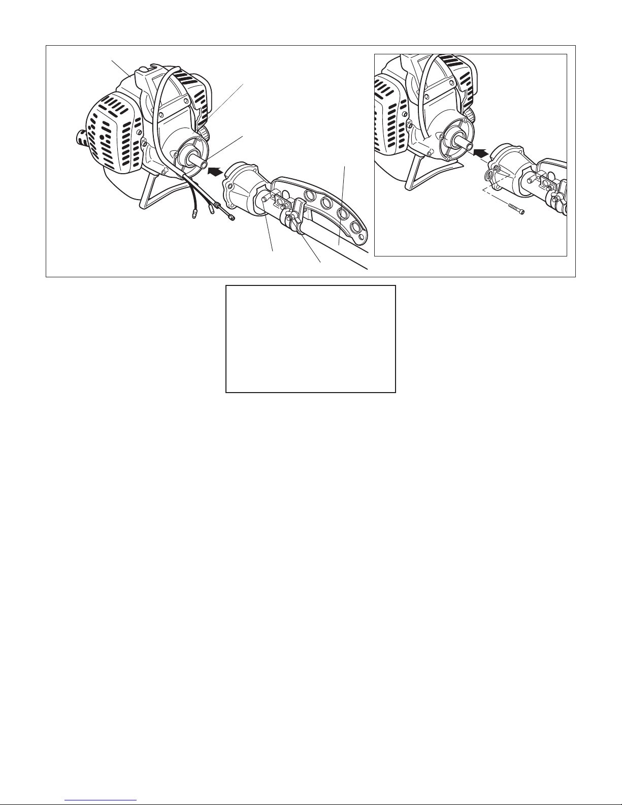
Powerhead
B45003
B45002
Mainshaft
Powerhead
Outer Tube
Figure 5
Fan Cover Housing
Swivel Lock
The B450 is equipped with a swivel feature that allows
the outer tube (and cutting attachment) to be rotated
without rotating the powerhead. Tightening the swivel
lock prevents outer tube rotation.
Figure 5A
Swivel Grease
Plug
Install Mainshaft and Outer Tube
1. Place the powerhead on a flat surface,
resting on its stand.
2. Lubricate the mainshaft splines with mo
-
lybdenum disulfide (moly) type grease.
3. Slide the outer tube/cap assembly on to
the fan cover. Make sure the mainshaft
splines are fully engaged into the clutch
drum. See Figure 5.
CAUTION!
Do not force the outer tube into the
powerhead! Forcing the outer tube
into the powerhead may damage the
splines on the mainshaft and/or clutch
drum shaft. If installation proves difficult, rotate the powerhead or mainshaft
until you feel the mainshaft splines
engage into the clutch drum.
4. If necessary, rotate the outer tube as
sembly until the gearcase output shaft
is pointing down, opposite to the spark
plug.
5. Install four screws with cable holder in
upper right mounting position as shown
in Figure 5A. Tighten all screws evenly
to 26-44 in/lbs.
6. Test swivel operation by rotating outer
tube. If necessary loosen the swivel lock
wing nut.
7
ENGLISH
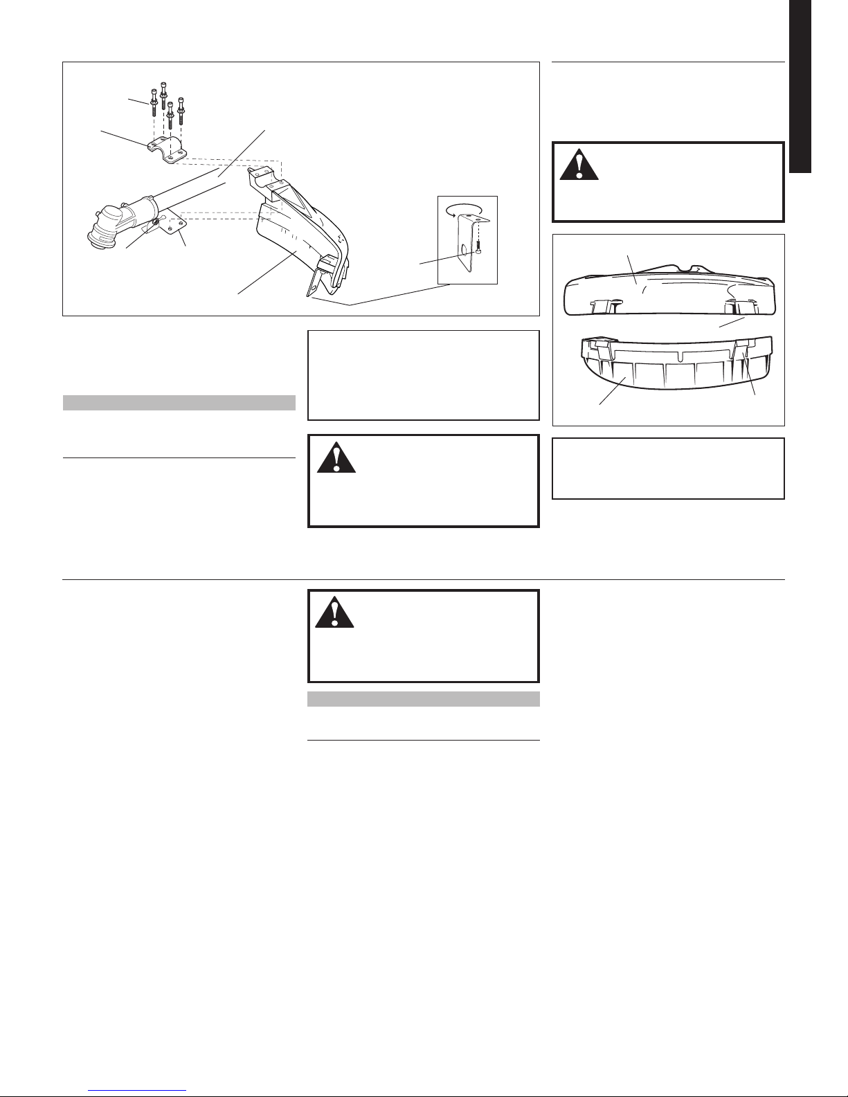
Install the Cutting Attachment Shield
Assembly and Adjustments
Bracket
1. Insert the cutting attachment shield
between the outer tube and the
cutting attachment shield mounting
plate. See Figure 6.
WARNING!
NEVER operate the unit without the
cutting attachment shield installed and
tightly secured!
CAUTION!
Make sure the clamp screw and
retaining nut are securely tightened
before tightening the four socket-head
cap screws.
NOTE:
It may be necessary to loosen the retaining nut
and clamp screw to adjust cutting attachment
shield mounting plate.
2. Tighten the four socket-head cap screws
to secure the cutting attachment shield.
WARNING!
The line cutter is very sharp. Wear
gloves to protect your hands when
handling.
To Change Position of Line Cutter.
1. Remove the 2 hex screws with a 4mm
hex wrench. See Figure 6A.
2. Rotate line cutter. See Figure 6A.
3. Reinstall the two hex screws and tighten
them securely.
NOTE:
Be careful to not lose the 2 nuts in the cutting
attachment shield, they are not captured.
The line cutter can be positioned in
2 positions to obtain different line length
for cutting.
Sub-Shield.
(when trimmer head is in use)
1. Attach the shield extension to the
cutting attachment shield.
WARNING!
NEVER use this machine without subshield when using a trimmer head.
CAUTION!
Make sure the sub-guard is completely
hooked at the hook receiver.
Sub-shield
Hook
Hook
Receiver
Cutting Attachment Shield
Figure 6
Line Cutter
Figure 6A
Hex
Screws
Socket-head
Cap Screws
Nut
Bracket
Cutting Attachment Shield
Outer Tube
Cutting
Attachment Shield
Mounting Plate
8
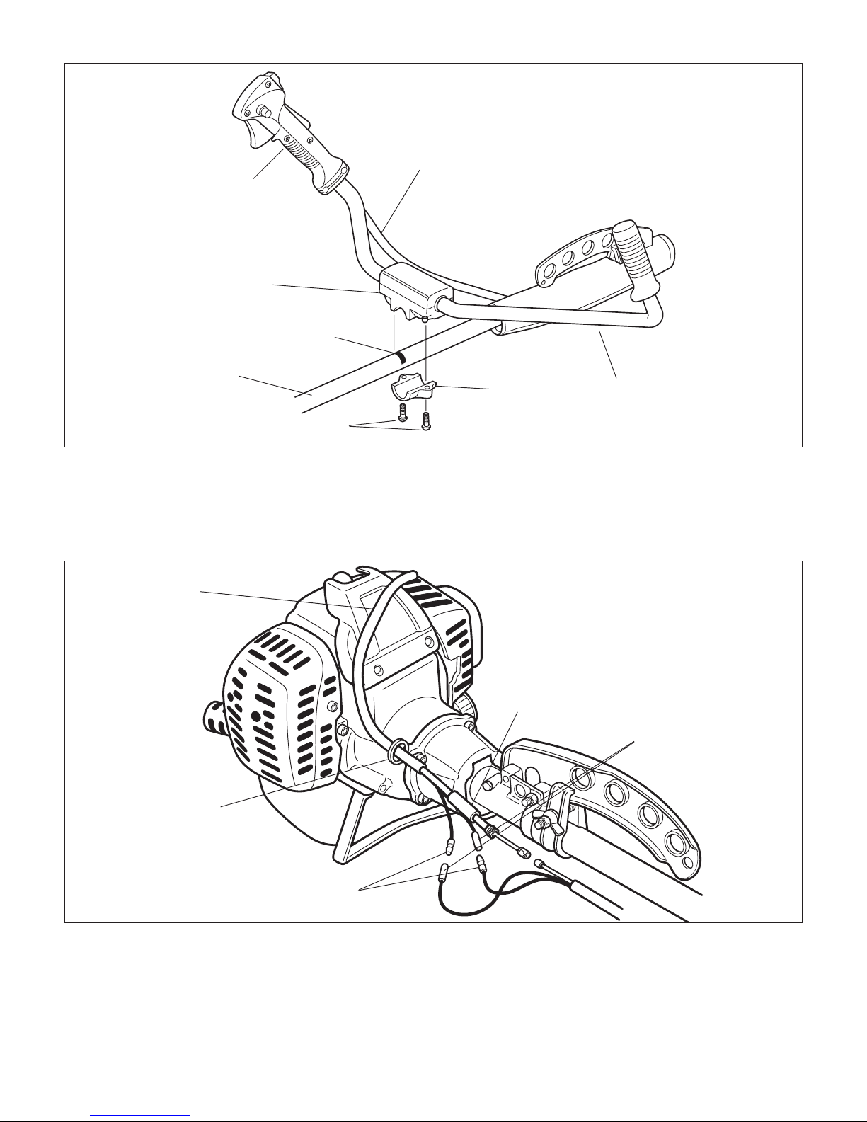
Handlebar
Assembly and Adjustments
B45006
Handlebar
Throttle Assembly
Outer Tube
Lower Cap Retaining Screws
Handlebar
Bracket
Throttle Cable
Installation Decal
Cap
Figure 7
1. Remove the 4mm retaining screw
and lower cap from the handlebar
bracket. See Figure 7.
2. Mount the handlebar on the outer tube
and align it with the “Attach Handle
On This Line” decal.
3. Reinstall the lower cap and retaining
bolts. Tighten the retaining screws
evenly.
B45007
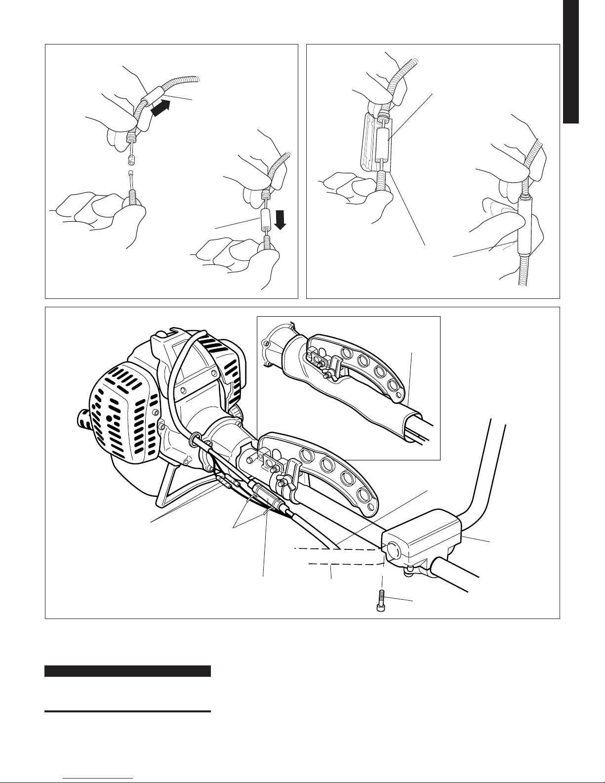
Cable Holder
Throttle Cable
Sleeve
Male Stop Switch
Connectors
Powerhead
Throttle
Cable
Figure 8
Female Stop Switch
Connectors
Throttle Cable
1. Route the powerhead throttle cable
through the cable holder. See Figure 8.
2. Install the throttle cable sleeve on the
powerhead throttle cable. See Figure 8.
3. Connect the stop switch wire connectors
(two wires). See Figure 8.
9
ENGLISH
Throttle Cable (Continued)
Assembly and Adjustments
B45012
B45011
B45010
B45009
B45008
Throttle Cable
Sleeve
Throttle Cable
Connector
Throttle Cable
Sleeve
Stop Switch Termi
-
nals
Cable Connector
Cable Ties
Hip Protector
Throttle Cable
Figure 9
Figure 11
Connecting Throttle Cable Ends Installing the
Connector
Figure 10
Throttle Cable
Sleeve
Throttle Control Adjustment
Handlebar
Handlebar
Bracket
Handlebar Bracket Cap Screw
4. Connect the powerhead throttle cable
with the throttle cable from the handle
-
bar. See Figure 9.
IMPORTANT!
Make sure the metal end of the
powerhead throttle cable jacket fits in the
grooved end of the cable connector
5. Center the throttle cable sleeve over
the connected cable ends and place the
assembly in the throttle cable connector.
See Figures 9, 10.
6. Close the throttle cable connector using
hand pressure. See Figure 10.
7. Secure each end of the throttle connector
with a cable tie. See Figure 11.
8. Install the hip protector on the outer
tube. See inset of Figure 11.
10
B45014
B45013
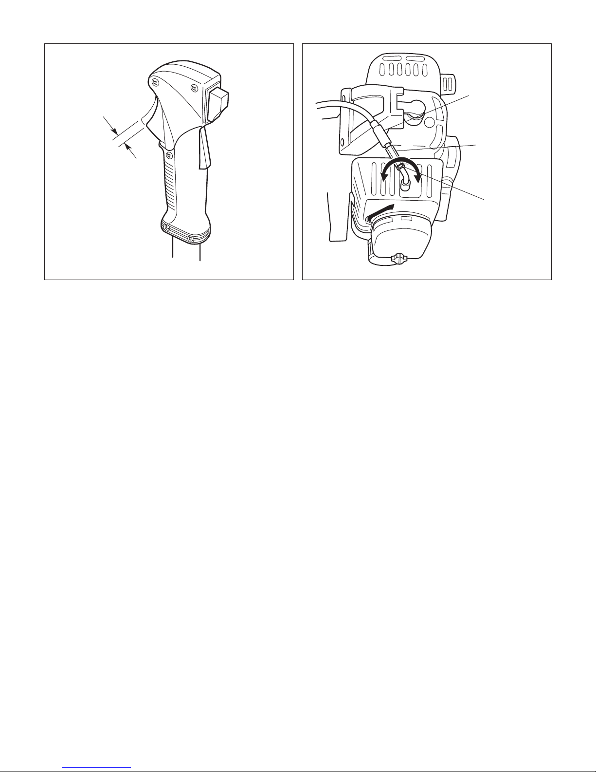
7 mm Free Play
Figure 12
Adjuster Cover
Cable Locknut
Cable Adjuster
Figure 13
Adjust Throttle
Assembly and Adjustments
1. Test throttle control for smooth operation. If stiffness or binding are noted, the
cause must be identified and corrected
before the brushcutter can be placed in
service.
2. Check the throttle control lever “Free
Play” clearance. “Free Play” should be
approximately 0.275 inches (7 mm) in
the idle position. See Figure 12.
3. If necessary, the “Free Play” clear
ance can be adjusted as follows.
See Figure 13.
a. Slide the adjuster cover up to expose
the cable adjuster.
b. Loosen the cable locknut.
c. Thread or unthread the cable
adjuster until the throttle control
lever has approximately 0.275
inches (7 mm) of “Free Play”
clearance.
d. Tighten the cable locknut.
e. Slide the adjuster cover over the
cable adjuster.
11
ENGLISH
B45016
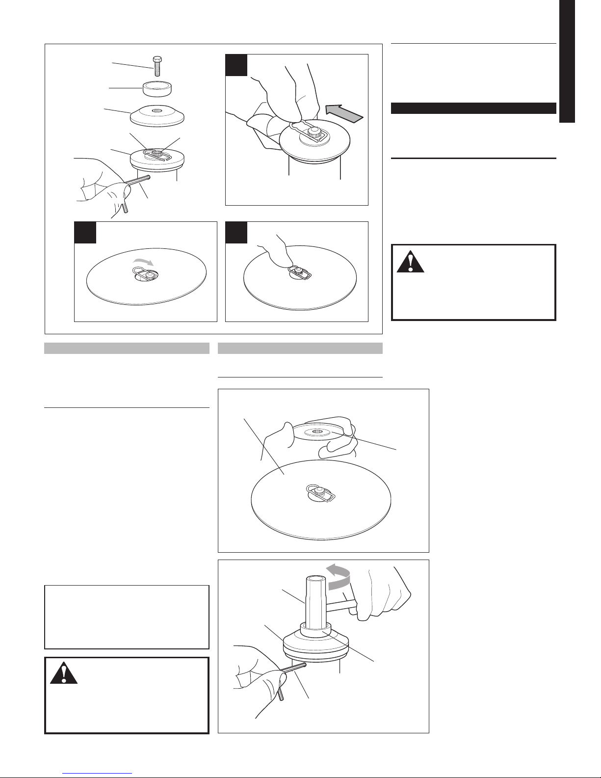
CAUTION!
Install the blade so its printed surface
is visible to the operator when the
brushcutter is in the normal operating
position.
WARNING!
The blade must fit flat against the
holder flange. The blade mounting
hole must be centered over the raised
boss on blade holder A.
5. Lock the blade on the shaft by centering
the safety clip. See Figure 14C.
6. Install holder B on the gearcase shaft.
See Figure 15.
IMPORTANT!
The machined recess in Holder B must
completely surround the safety clip, and
both holders must be flat against the sur
-
face of the blade.
7. Lock holder A to the gearcase by insert
ing the long end of the hex wrench
through both holes as done in step 1
and tighten the shaft bolt securely with
the combination spark plug/screwdriver
wrench. See Figure 16.
8. Remove the hex wrench.
WARNING!
The blade must fit flat against the
holder flange. The blade mounting
hole must be centered over the raised
boss on blade holder A.
B45017
B45015
B45018
Safety Clip
Gearcase
Shaft
Shaft Bolt
Bolt Guard
Holder A
Holder B
Figure 14
Blade
Assembly and Adjustments
Hex
Wrench
A
Slip the safety clip
off-center
C
Center the safety clip
B
Slip the blade in place
NOTE:
The B450 is shipped with Holder A, the
safety clip, Holder B, shaft bolt, and bolt
guard installed. The shaft bolt is a LEFTHAND THREAD AND IS REMOVED IN A
CLOCKWISE ROTATION!
1. With the gearcase output shaft facing
up, rotate the gearshaft and holder A
until the hole in holder A aligns with the
matching hole in the gearcase flange,
and then lock the holder to the gearcase
by inserting the long end of the hex
wrench through both holes.
See Figure 14.
2. Remove the shaft bolt, bolt guard and
holder B. See Figure 14.
3. Slide the safety clip off center on the
gearcase shaft. See Figure 14A.
4. Slide the blade over the safety clip
and onto the flange on holder A.
See Figure 14B.
B45019
Install
Holder "B"
Blade
Figure 15
B45020
Figure 16
Tighten the assembly
Holder "B"
Bolt Guard
Combination Spark
Plug/Screwdriver
Wrench
Hex Wrench
A
NOTE:
When installing certain blades, it may be nec
-
essary to temporarily remove the safety clip.
12
B45022
B45021
Assembly
Safety Clip
(not used)
Shaft Bolt
(not used)
Bolt Guard
(not used)
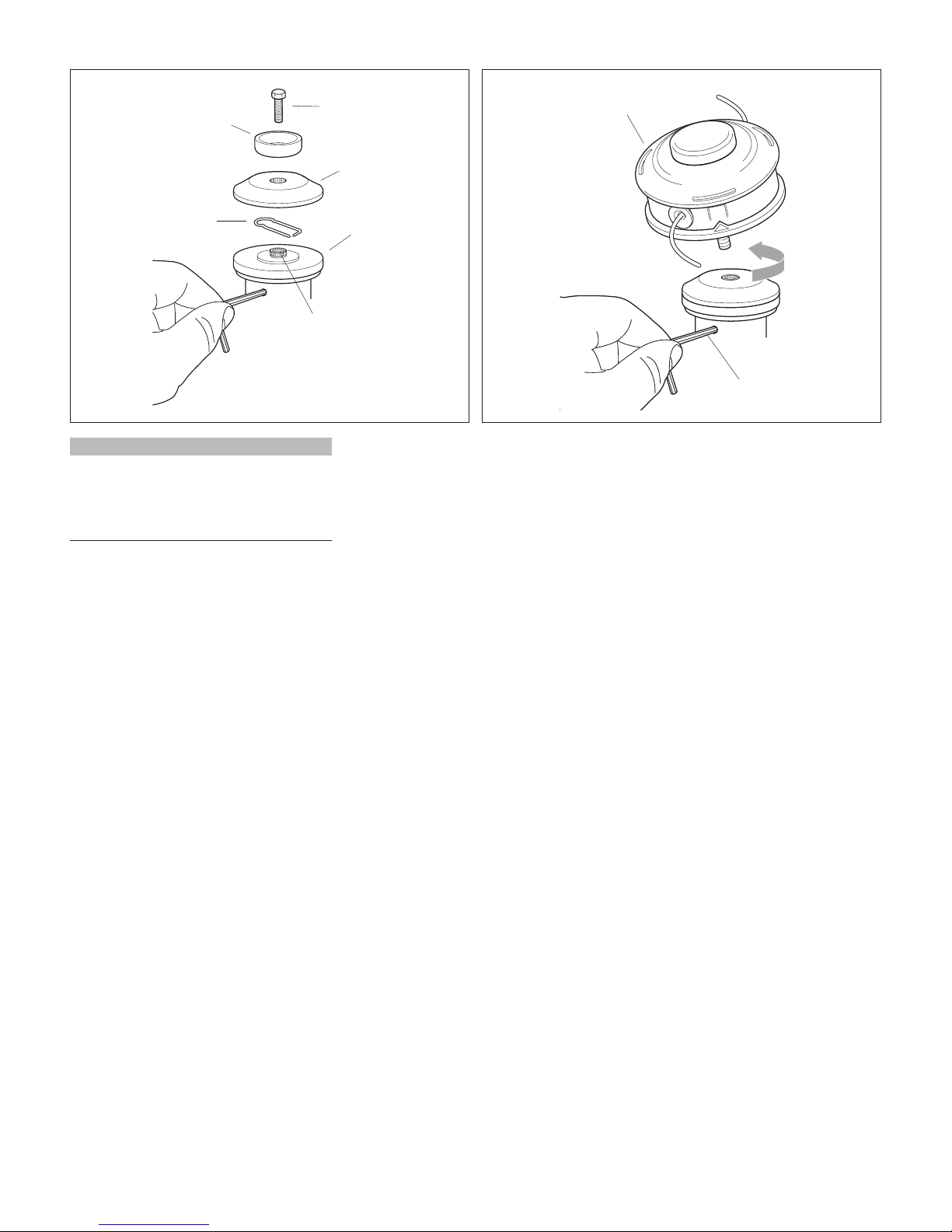
NOTE:
The B450 is shipped with Holder A, the blade
retainer (safety clip), Holder B, shaft bolt,
and bolt guard installed. The shaft bolt is a
LEFT-HAND thread. Remove it by turning
CLOCKWISE!
1. With the gearcase output shaft facing
up, rotate the gearshaft and holder A
until the hole in holder A aligns with the
matching hole in the gearcase flange,
and then lock the holder to the gearcase
by inserting the long end of the hex
wrench through both holes.
See Figure 17.
Gearcase
Shaft
Hex Wrench
Holder B
Holder A
Hand-tighten Trimmer Head
(counter-clockwise to install)
Figure 17
Trimmer Head
2. Using the combination spark plug/
screwdriver wrench, remove the shaft
bolt, bolt guard, holder B and the safety
clip. (The bolt guard, shaft bolt and
safety clip are not used with a trimmer
head). See Figure 17.
3. Install Holder B on the gearcase shaft.
The splined hole on Holder B must
engage with the gearcase shaft.
4. Using the hex wrench to secure Holder
A , install and hand-tighten the trimmer
head (counter-clockwise to install).
See Figure 18.
Figure 18
5. Remove the hex wrench from the
gearcase and holder.
13
ENGLISH
IMPORTANT!
Mix only enough fuel for your immediate
needs! If fuel must be stored longer than
30 days and Shindaiwa One oil with fuel
stabilizer is not used, it should first be
treated with a fuel stabilizer such as STABIL™.
Starting the Engine
IMPORTANT!
Engine ignition is controlled by a two position switch mounted on the throttle housing labeled, "I" for ON or START and "O" for OFF
or STOP.
Mixing Fuel
1. Place the brushcutter on a flat, level
surface.
2. Clear any dirt or other debris from
around the fuel filler cap.
3. Remove the fuel cap, and fill the tank
with clean, fresh fuel.
4. Reinstall the fuel filler cap and tighten
firmly.
Filling the Fuel Tank
WARNING!
Minimize the risk of fire!
STOP engine before refueling.
ALWAYS allow the engine to cool
before refueling!
Wipe all spilled fuel and move the
engine at least 10 feet (3 meters)
from the fueling point and source
before restarting!
NEVER start or operate this
unit if there is a fuel leak.
NEVER start or operate this
unit if the carburetor, fuel lines, fuel
tank and/or fuel tank cap are damaged.
NEVER smoke or light any fires near
the engine or fuel source!
NEVER place any flammable mate-
rial near the engine muffler!
NEVER operate the engine without
the muffler and spark arrester in good
working condition.
CAUTION!
This engine is designed to operate on
a 50:1 mixture consisting of unleaded
gasoline and a premium 2-cycle mixing
oil only. Use of non-approved mixing
oils can lead to excessive maintenance
costs and/or engine damage.
CAUTION!
Some types of gasoline contain al-
cohol as an oxygenate. Oxygenated
gasoline may cause increased operating temperatures. Under certain
conditions, alcohol-based gasoline
may also reduce the lubricating
qualities of some 2-cycle mixing oils.
Never use any type of gasoline
containing more than 10% alcohol
by volume! Generic oils and some
outboard oils may not be intended
for use in high-performance 2-cycle
type engines, and should never be
used in your Shindaiwa engine.
Use only fresh, clean unleaded gasoline
with a pump octane of 87 or higher.
Mix gasoline with 50:1 Shindaiwa
Premium 2-cycle mixing oil or with
an equivalent high quality 2-cycle
mixing oil.
Examples of 50:1 mixing quantities:
1 gallon of gasoline to 2.6 oz. mixing oil
5 liters of gasoline to 100 ml. mixing oil
Oil is a registered JASO FC
classified oil and also meets or exceeds
ISO-L-EGD performance requirements.
Shindaiwa One is recommended for
use in all Shindaiwa low emissions engines.
Shindaiwa One also includes
a fuel stabilizer.
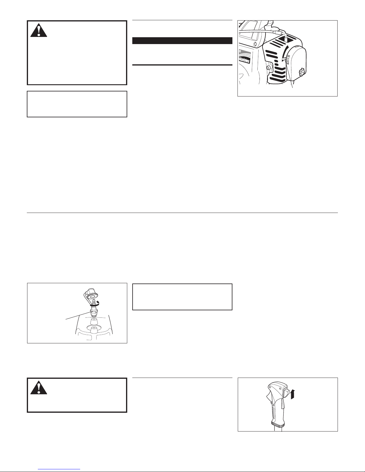
B45026
Choke Lever
(closed)
Figure 22
B45024
ON
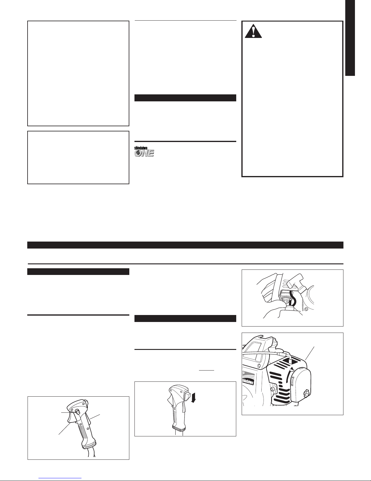
Figure 20
B45023
Throttle Control
Lever B
Throttle
Control
Lockout
Lever A
Throttle
Control Lock
Button C
Figure 19
Primer Bulb
IMPORTANT!
Normally, the engine can be started
without setting the throttle control to the
fast idle position. However, if the engine is
difficult to start or stalls immediately after
starting, set the throttle control to the fast
idle setting as described in step 1.
1. Set the throttle lever to “fast idle” by
performing the following:
a. Depress and hold throttle lockout
lever A.
b. Squeeze and hold throttle lever B
(toward the handgrip).
c. Depress and hold throttle lever lock
button C.
d. While depressing throttle lever lock
C, release throttle lock lever B and
lockout lever A. See Figure 19.
IMPORTANT!
The primer system only pushes fuel
through the carburetor. Repeatedly
pressing the primer bulb will not flood the
engine with fuel.
2. Slide the ignition switch to I (ON) position. See Figure 20.
3. Prime the engine by repeatedly
depressing the carburetor primer bulb
until fuel can be seen flowing through
the transparent overflow return tube.
See Figure 21.
4. (Cold Engine Only) Choke the engine
by moving the choke lever up towards
the spark plug (choke is closed). See
Figure 22.
B45025
Figure 21
14
WARNING!
Before starting the engine, make sure
children, bystanders, and pets and/or
any other objects are well clear of the
cutting attachment! The cutting attach
ment will rotate when the engine is
started with the throttle control set in
the “fast idle” position.
CAUTION!
Never operate the brushcutter without a
cutting attachment installed!
5. Place the unit firmly on the ground.
6. Hold the outer tube firmly with your left
hand and grasp the starter handle with
your right hand.
7. Pull the starter cord out slowly until you
feel the starter engage.
8. Pull the starter handle outward rapidly
to start the engine.
3. If the spark plug electrodes and ceramic
insulator are fouled or soaked with fuel,
clean or replace the plug. For spark plug
specifications and gapping procedure,
refer to page 18.
4. Open the choke.
5. Hold the throttle control lever depressed
and crank the engine several times to
clear excess fuel from the combustion
chamber.
CAUTION!
Incorrect spark plug installation may
cause serious engine damage!
Starting the Engine (continued)
B45028
Spark Plug
Turn counter-
clockwise to remove
Figure 24
Starting a Flooded Engine
IMPORTANT!
The recoil starter can provide long-lasting
trouble free operation by following these
recommendations:
Always engage the starter before at-
tempting to start the engine.
Never pull the cord to its maximum
limit.
Always allow the cord to rewind slowly
into the starter.
When the engine starts
or attempts to start—
9. Move the choke lever down to the “open
choke” position. See Figure 23.
Stopping the Engine
WARNING!
The cutting attachment may continue to
rotate after the engine has stopped!
1. Slide the ignition switch button to the
STOP position.
2. Disconnect the spark plug wire, and
remove the spark plug. See Figure 24.
OFF
B45029
Figure 25
B45027
Choke Lever (open)
Figure 23
10. If the engine stalls, repeat the applicable starting procedure for a warm or
cold engine.
11. When the engine starts, clear excess
fuel from the combustion chamber
by revving the engine a few times.
Operation of the throttle control lever
will automatically disengage the “fastidle” lock and return the engine to idle.
If the engine does not start—
Repeat the applicable starting procedures
for a warm or cold engine. If the engine
fails to start, refer to the “Starting a
Flooded Engine" section below.
6. Reinstall the spark plug finger-tight and
tighten it firmly with the spark plug
wrench provided in the tool kit. If a
torque wrench is available, torque the
spark plug to 148-165 in.-lb. (170-190 kgf
cm).
7. Repeat the “warm engine” starting
procedure.
8. If the engine fails to start, consult the
troubleshooting guide provided
on page 20.
1. Allow the engine to idle for two or three
minutes to stabilize temperatures.
2. Slide the ignition switch button to the
STOP position. See Figure 25.
Make sure the cutting attachment is clear
of obstructions!
15
ENGLISH
NEVER operate the unit with the cutting attachment shield or other protective
devices removed!
WARNING!
A cutting attachment shield or other
protective device is no guarantee of
protection against ricochet. YOU MUST
ALWAYS GUARD AGAINST FLYING
DEBRIS!
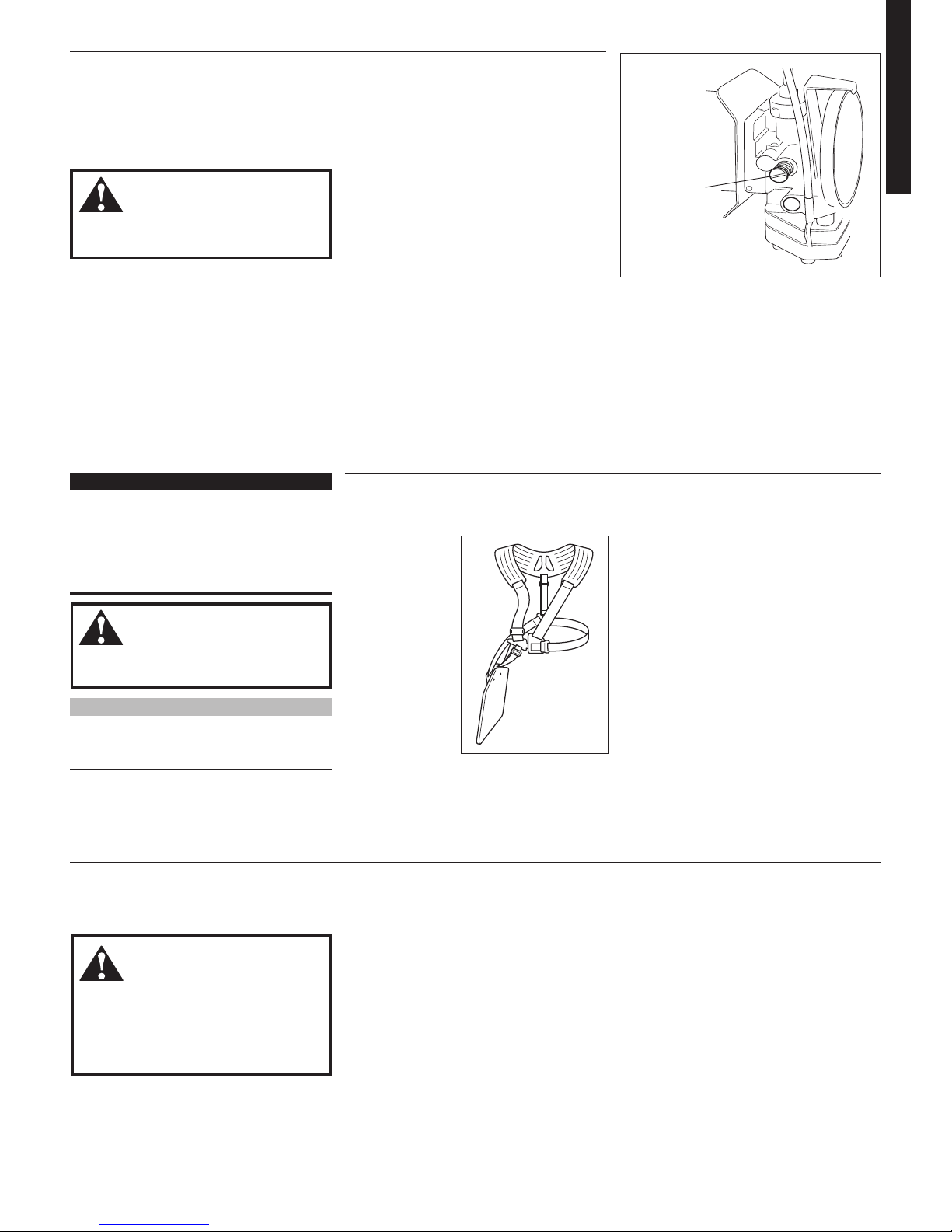
Double Shoulder Harness
Adjust the double shoulder harness straps
so the shoulder pads rest comfortably on
the offside of the
shoulder and the
cutting path of the
blade is parallel to
the ground. Make
sure all hooks and
adjusting devices
are secure. See
Figure 27.
IMPORTANT!
Adjust the shoulder strap so the shoulder pad rests comfortably on the off-side
shoulder and the cutting path of the cutting attachments is parallel to the ground.
Make sure all hooks and adjustment
devices are secure.
WARNING!
Always wear a harness when operating
this unit with a blade.
Units equipped with emission
control system
Units with emission control systems are
equipped with factory preset carburetor
mixture adjustments. These units can not
be readjusted in the field.
Shoulder Strap & Harness
Checking Unit Condition
B45045
Adjusting Engine Idle
1. Start the engine, and allow it to idle 2-3
minutes to warm up.
3. If a tachometer is available, adjust
engine idle speed to 2,750 ±250 rpm
(min-1).
3. If a tachometer is not available and the
cutting attachment rotates while the
engine is idling, turn the idle adjustment
screw counterclockwise until the
cutting attachment stops rotating.
See Figure 26.
B45031A
Figure 26
Idle Speed
Adjustment
WARNING!
The cutting attachment must NEVER
rotate at engine idle speeds!
The engine should return to normal idle
speed whenever the throttle control lever
is released. Idle speed is adjusted to permit
the clutch mechanism to disengage power
to the cutting attachment whenever the
engine is idling at the specified setting. To
adjust the idle speed:
Use only authorized Shindaiwa parts and
accessories with your Shindaiwa trimmer.
Do not make modifications to your unit
without the written approval of Shindaiwa,
Inc.
ALWAYS make sure the cutting attachment is properly installed and firmly tight
-
ened before operation.
NEVER use a cracked or warped cutting at-
tachment: replace it with a serviceable one.
ALWAYS make sure the cutting attach-
ment fits properly into the appropriate
attachment holder. If a properly installed at
tachment vibrates, replace the attachment
with new one and re-check.
Figure 27
NOTE:
Using a harness with a brushcutter allows
you to maintain proper control of the unit and
reduces fatigue during extended operation.
Position of Hanger
Insert the harness hook in one of the four
holes in the hanger so that the unit is comfortably balanced.
ALWAYS stop the engine immediately and
check for damage if you strike a foreign
object or if the unit becomes tangled. Do
not operate with broken or damaged equip
-
ment.
NEVER operate a unit with worn or dam-
aged fasteners or attachment holders.
 Loading...