

Shimano SL-R440 - TECHNICAL, SL-R441 - TECHNICAL, SL-R440, SL-R441 Service Instructions Manual
General Safety Information
WARNING
•
Obtain and read the service instructions carefully prior to installing the
parts. Loose, worn, or damaged parts may cause injury to the rider.
We strongly recommend only using genuine Shimano replacement
parts.
• Read these Technical Service Instructions carefully, and keep them in
a safe place for later reference.
Note
• For smooth operation, use the specified outer casing and bottom
bracket cable guide.
• Grease the inner cable and the inside of the outer casing before use
to ensure that they slide properly.
• Use a frame with internal cable routing is strongly discouraged as it
has tendencies to impair the SIS shifting function due to its high
cable resistance.
• Operation of the levers related to gear shifting should be made only
when the front chainwheel is turning.
• Use an outer casing which still has some length to spare even when
the handlebars are turned all the way to both sides. Furthermore,
check that the shifting lever does not touch the bicycle frame when
the handlebars are turned all the way.
• A special grease is used for the gear shifting cable (SIS-SP41).Do
not use DURA-ACE grease or other types of grease, otherwise they
may cause deterioration in gear shifting performance.
• Do not disassemble the indicator and shifting lever unit, as this may
damage them or cause mis-operation.
• Parts are not guaranteed against natural wear or deterioration
resulting from normal use.
• For maximum performance we highly recommend Shimano lubricants
and maintenance products.
• For any questions regarding methods of installation, adjustment,
maintenance or operation, please contact a professional bicycle
dealer.
Technical Service Instructions SI-6FH0C
SL-R440
SL-R441
Shifting lever
Please note:specifications are subject to change for improvement without notice. (English)
© Apr.2006 by Shimano Inc. XBC SZK Printed in Japan.
One Holland, Irvine, California 92618, U.S.A. Phone: +1-949-951-5003
Industrieweg 24, 8071 CT Nunspeet, The Netherlands Phone: +31-341-272222
3-77 Oimatsu-cho Sakai-ku, Sakai, Osaka 590-8577, Japan
These service instructions are
printed on recycled paper.
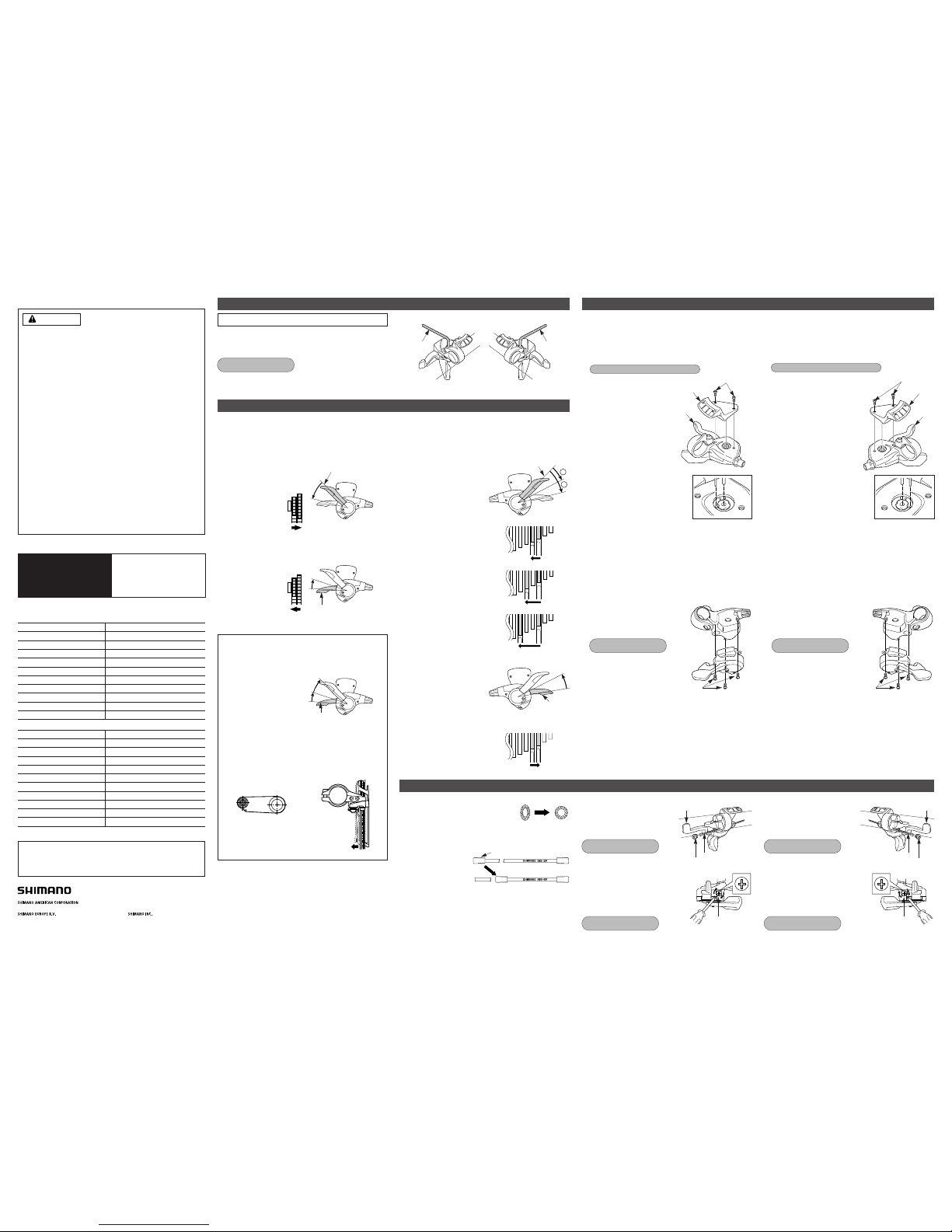
Mounting the shifting lever
Install the brake lever in a position where it will not obstruct brake
operation. Do not use in a combination which causes brake
operation to be obstructed.
Both lever (A) and lever (B) always return to the initial position when they are released after shifting.
When operating one of the levers, always be sure to turn the crank arm at the same time.
To shift from a small chainring to a larger chainring
When lever (A) is pressed once, there is a shift of one step from
a small chainring to a larger chainring.
Example:
from intermediate chainring
to largest chainring.
Use a handlebar grip with a maximum outer diameter of 32 mm.
Tightening torque :
5 N·m {44 in. lbs.}
< Front > < Rear >
5 mm Allen key 5 mm Allen key
Gear shifting operation
< Front >
Lever (A) initial position
To shift from a large chainring to a smaller chainring
When lever (B) is pressed once, there is a shift of one step from
a large chainring to a smaller chainring.
Example:
from largest chainring
to intermediate chainring.
Lever (B)
When lever (B) is operated, there is one click where trimming
(the noise prevention mechanism) engages, and a second
stronger click when the gear shift stroke is completed. After
trimming, the next push will complete the gear shift stroke.
Trimming (noise prevention operation)
If the chain is on the large front chainwheel and the larger rear
sprocket, the chain will rub in the front derailleur plate,
producing a characteristic noise. When this happens, press lever
(B) lightly (to the point where it clicks); this causes the front
derailleur to move slightly towards the smaller chainwheel,
thereby eliminating the noise.
Gear shift
complete stroke
Click
Trim operation
Click
Lever (B)
Movement of the front
derailleur
Chain position
To shift from a small sprocket to a larger sprocket
To shift one step only, press lever (A) to the 1 position.
To shift two steps at one time,
press to the 2 position.
< Rear >
1
2
Lever (A) initial position
1 : Shifts one sprocket
E.x. : from 3rd to 4t
2 : Quick-shifts two sprockets
E.x. : from 3rd to 5th
3 : Quick-shifts three sprockets
E.x. : from 3rd to 6th
4 3
35
3
6
Installing the shifting cable
To shift from a large sprocket to a smaller sprocket
Press lever (B) once to shift one
step from a larger to a smaller
sprocket.
Lever (B)
E.x. : from 4th to 3rd
34
Replacement of the shifting lever unit and indicator
Removal of the indicator
Disassembly and reassembly should only be carried out when
replacing the indicator.
1. Remove the two indicator set screws which are securing the
indicator.
2. Remove the indicator unit as
shown in the illustration.
3. Operate lever (B) two times or
more to set the lever to the lowest
position.
4. After checking that the indicator needle
is at the right edge, install the indicator
as shown in the illustration.
5. Check the operation of the indicator. If it does not operate
correctly, re-install the indicator by while taking particular note of
steps 3. and 4.
< Front >
Removal of the indicator
Disassembly and reassembly should only be carried out when
replacing the indicator.
1. Remove the two indicator set screws which are securing the
indicator.
2. Remove the indicator unit as
shown in the illustration.
3. Operate lever (B) at least eight
times to set the lever to the
highest position.
4. After checking that the indicator needle
is at the left edge, install the indicator
as shown in the illustration.
5. Check the operation of the indicator. If it does not operate
correctly, re-install the indicator by while taking particular note of
steps 3. and 4.
< Rear >
Tightening torque : 0.3 - 0.5 N·m {3 - 4 in. lbs.}
Tightening torque : 0.3 - 0.5 N·m {3 - 4 in. lbs.}
Indicator set screws
Indicator
Lever (B)
Indicator set screws
Lever (B)
Indicator
Replacement of the shifting lever unit
Disassembly and reassembly should only be carried out when
replacing the shifting lever unit.
1. Loosen the cable fixing bolt (nut) of the front derailleur, and then
pull the inner cable out of the shifting lever unit in the same way
as when installing the inner cable.
2. Carry out steps 1 - 2 for replacement of the indicator.
3. Remove the three shifting lever
mounting screws, and then remove the
shifting lever unit as shown in the
illustration.
Tightening torque :
0.5 - 0.8 N·m {4 - 7 in. lbs.}
Shifting lever mounting screws
Replacement of the shifting lever unit
Disassembly and reassembly should only be carried out when
replacing the shifting lever unit.
1. Loosen the cable fixing bolt (nut) of the rear derailleur, and then
pull the inner cable out of the shifting lever unit in the same way
as when installing the inner cable.
2. Carry out steps 1 - 2 for replacement of the indicator.
3. Remove the three shifting lever
mounting screws, and then remove the
shifting lever unit as shown in the
illustration.
Tightening torque :
0.5 - 0.8 N·m {4 - 7 in. lbs.}
Shifting lever mounting screws
4. To assemble, align the shifting lever unit and the brake lever
bracket and then secure the shifting lever mounting screws.
5. Carry out steps 3 - 4 for replacement of the indicator.
4. To assemble, align the shifting lever unit and the brake lever
bracket and then secure the shifting lever mounting screws.
5. Carry out steps 3 - 4 for replacement of the indicator.
Cutting the outer casing
When cutting the outer casing, cut the
opposite end to the end with the marking.
After cutting the outer casing, make the
end round so that the inside of the hole
has a uniform diameter.
Attach the same outer end
cap to the cut end of the
outer casing.
Outer end cap
Installing the inner cable < Front >
Operate lever (B) two times or more,
and check on the indicator that
the lever is at the lowest position.
Then remove the inner hole cover
and connect the inner cable.
Install the inner hole cover by turning
it as shown in the illustration until it
stops.
Do not turn it any further than this,
otherwise it may damage the screw
thread.
Lever (B)
Inner hole cover
Inner cable
Inner hole cover
Tightening torque:
5 - 7 N·m {44 - 60 in. lbs.}
Tightening torque:
0.3 - 0.5 N·m {3 - 4 in. lbs.}
Installing the inner cable < Rear >
Operate lever (B) eight times or more,
and check on the indicator that
the lever is at the highest position.
Then remove the inner hole cover
and connect the inner cable.
Install the inner hole cover by turning
it as shown in the illustration until it
stops.
Do not turn it any further than this,
otherwise it may damage the screw
thread.
Lever (B)
Inner hole cover
Inner cable
Inner hole cover
Tightening torque :
5 - 7 N·m {44 - 60 in. lbs.}
Tightening torque :
0.3 - 0.5 N·m {3 - 4 in. lbs.}
F : SL-R441 R : SL-R440
SP41
27
FD-R443 / FD-R453
FC-4404 / FC-4503
BB-ES51/30 / SM-FC4500
RD-4400 / RD-4500
FH-4400 / FH-4500
CS-HG50-9
CN-HG53
SM-SP17
F : SL-R441 R : SL-R440
SP41
18
FD-R440 / FD-R450
FC-4401 / FC-4500 / FC-4550
BB-ES51/30 / SM-FC4500
RD-4400 / RD-4500
FH-4400 / FH-4500
CS-HG50-9
CN-HG53
SM-SP17
In order to realize the best performance, we recommend that the
following combination be used.
Shifting lever
Outer casing
Gears
Front derailleur
Front chainwheel
Bottom bracket
Rear derailleur
Freehub
Cassette sprocket
Chain
Bottom bracket cable guide
Shifting lever
Outer casing
Gears
Front derailleur
Front chainwheel
Bottom bracket
Rear derailleur
Freehub
Cassette sprocket
Chain
Bottom bracket cable guide
This service instruction explains how to use and maintain the Shimano
bicycle parts which have been used on your new bicycle.
For any questions regarding your bicycle or other matters which are not
related to Shimano parts, please contact the place of purchase or the
bicycle manufacturer.
 Loading...