

SI-34R0B
SG-8R20
SG-8R25
CJ-8S20
Left
Fork end
Non-turn washer
Reversed
Standard
5R/ Yellow
6R/ Silver
5L /Brown
6L /White
Mark/ Color
Size
Right
7R/ Black 7L /Gray
Reversed
(full chain case)
5R/ Yellow
= 0
= 0
5L /Brown
7R
CJ-8S20
JAPAN
LOCK
CJ-8S20
JAPAN
LOCK
CJ-8S20
JAPAN
C
J-8S
2
0
J
AP
A
N
LOCK
6R
CJ-8S20
JAPAN
LOCK
C
J-8S
2
0
J
A
PAN
LOCK
7R
GREASE
7R
CJ-8S20
JAPAN
LOCK
CJ-8S20
JAPAN
Right side of
the hub body
3.
1.
1.
2.
General Safety Information
WARNING
– To avoid serious injuries:
NOTE:
You can shift gears while pedaling, but on rare occasions
the pawls and ratchet inside the hub may produce some
noise afterwards as part of normal gear shifting operation.
The CJ-8S20 cassette joint should only be used with
sprockets from 16T to 23T.
If the wheel becomes stiff and difficult to turn, you should
lubricate it with grease.
Do not apply any grease to the inside of the hub,
otherwise the grease will come out again.
You should periodically wash the sprockets in a neutral
detergent and then lubricate them again. In addition,
cleaning the chain with neutral detergent and lubricating it
can be a effective way of extending the useful life of the
sprockets and the chain.
If the chain keeps coming off the sprockets during use,
replace the sprockets and the chain.
Parts are not guaranteed against natural wear or
deterioration resulting from normal use.
For maximum performance we highly recommend
Shimano lubricants and maintenance products.
For any questions regarding methods of handling or
adjustment, please contact the place of purchase.
When securing the brake arm to the frame, be sure to
securely tighten the clip screw and clip nut to the
specified tightening torque. Use lock nuts with nylon
inserts (self-locking nuts) for the clip nut. It is
recommended that standard Shimano parts be used for
the clip screw, clip nut and brake arm clip. If the clip nut
comes off the brake arm, or if the clip screw or brake arm
clip becomes damaged, the brake arm may rotate on the
chainstay and cause the handlebars to jerk suddenly, or
the bicycle wheel may lock and the bicycle may fall over,
causing serious injury.
When installing the hub to the frame, be sure to install
the correct non-turn washers to the left and right sides,
and securely tighten the hub nuts to the specified
torques. If the non-turn washers are installed to one side
only, or if the hub nuts are not tightened sufficiently, the
non-turn washer may fall out, which could cause the hub
axle to rotate and the cassette joint to turn. This may
then cause the handlebars to be accidentally pulled by
the shifting cable, and an extremely serious accident
could result.
Obtain and read the service instructions carefully prior to
installing the parts. Loose, worn, or damaged parts may
cause serious injury to the rider.
We strongly recommend only using genuine Shimano
replacement parts.
Check that the wheels are fastened securely before
riding the bicycle. If the wheels are loose in any way,
they may come off the bicycle and serious injury may
result.
Read these Technical Service Instructions carefully, and
keep them in a safe place for later reference.
Technical Service Instructions
Be sure to read these service instructions in conjunction
with the service instructions for the Inter-M Brake and the
Inter-8 shifting lever before use.
These service instructions explain how to use and maintain
the Shimano bicycle parts which have been used on your
new bicycle. For any questions regarding your bicycle or
other matters which are not related to Shimano parts‚ please
contact the place of purchase or the bicycle manufacturer.
Jul. 2003 by Shimano Inc. PIT. SZK. Printed in China
C
One Holland Irvine CA 92618 U.S.A. Phone 949- 951-5003
Industrieweg 24 NL-8071 CT Nunspeet‚ Holland Phone 31-341-272222
3-77 Oimatsucho‚ Sakai‚ Osaka‚ Japan Phone 072-223-3243
Please note: Specifications are subject to change for improvement without
notice. (English)
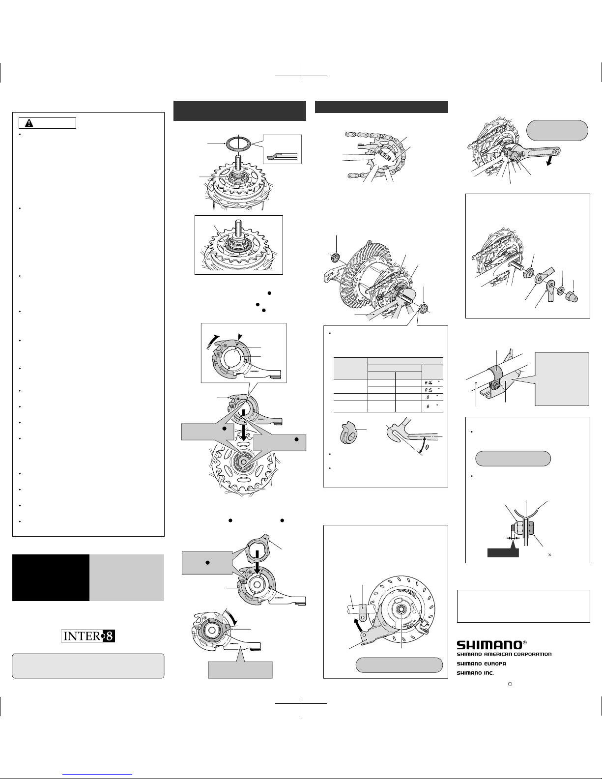
When installing the brake arm clip, securely
tighten the clip screw while holding the clip nut
with a 10 mm spanner.
Note:
After installing the brake arm clip, check that the
clip screw protrudes about 2 – 3 mm from the
surface of the clip nut.
Clip nut
Brake arm
Brake arm clip
Clip screw
(M6 16 mm)
Take up the slack in the chain and secure the wheel to
the frame with the cap nuts.
2 – 3 mm
Non-turn washer
Cap nut
4.
5.
Tightening torque:
2 – 3 Nm {17 – 26 in. lbs.}
Tightening torque:
30 – 45 Nm
{260 – 390 in. lbs.}
Fix the brake arm of the Inter-M brake securely to the
chainstay with the brake arm clip.
Brake arm clip
Chainstay
Brake arm
Note:
When installing a part such as a mudguard stay to
the hub axle, install in the order shown in the
illustration below.
Non-turn washer
Washer
Cap nut
Carrier stay
Mudguard stay
If excessive force is
applied to the brake
arm, the wheel will
become difficult to
turn. Make sure that
you don't apply
excessive force
when installing.
Install the brake arm of the Inter-M brake to the
chainstay with the brake arm clip, provisionally tighten
the clip screw and clip nut, and then tighten the brake
unit fixing nut.
Tightening torque:
20 – 25 Nm {174 – 217 in. lbs.}
Brake unit fixing nut
Brake arm clip
Chainstay
Brake arm
3.
Note:
If the brake arm is in the incorrect position as
shown in the illustration so that it cannot be
provisionally installed to the chainstay, loosen the
brake unit fixing nut and turn the brake arm. Then,
after provisionally securing the brake arm to the
chainstay, tighten the brake unit fixing nut.
Cassette joint
Groove of fork end
Chainstay
Non-turn
washer
(for right side)
Installation of the hub to the frame
Mount the chain on the sprocket, and then set the hub
axle into the fork ends.
Hub axle
Fork end
The projecting parts should be
on the fork end side.
Install the non-turn washers so that the
projecting parts is securely in the fork end
grooves on either side of the hub axle.
Different types of left and right non-turn washers
are available for use with standard and reversed
fork ends. Use whichever non-turn washers are
suitable.
Place the non-turn washers onto the right side and left
side of the hub axle. At this time, turn the cassette joint
so that the projecting parts of the non-turn washers fit
into the grooves of the fork ends. If this is done, the
cassette joint can be installed so that it is almost parallel
to the chainstay.
Mark
Non-turn washer (for left side)
Cassette joint fixing ring
Cassette joint
fixing ring
Cassette joint pulley
Align the
yellow marks
to install.
Install the driver cap to the driver on the right side of the
hub body.
2.
Turn the cassette joint pulley in the direction of the
arrow in the illustration to align the red marks on the
pulley and the bracket. With the cassette joint in this
condition, install it so that the red mark on the
cassette joint is aligned with the red mark on the right
side of the hub body.
Pulley
Bracket
Cassette joint
Driver cap
Driver cap
Driver
Should be aligned
Note the
direction
Secure the cassette joint to the hub with the cassette
joint fixing ring. When installing the cassette joint fixing
ring, align the yellow mark with the yellow mark on
the cassette joint pulley, and then turn the cassette joint
fixing ring 45° clockwise.
Installation of the cassette joint to
the hub
Fit the cassette joint
bracket securely.
Turn 45°
Align the red
marks to install.
Align the red
marks to install.
Inter-8 Hub
Cassette joint
20
38
CJ-8S20
JAPAN
LOCK
2 mm Allen key
or #14 spoke
Pulley hole
Turn the
pulley
Pull out from
the outer
casing holder
CJ-8S20
JAPAN
LOCK
3
1
Remove the inner
cable fixing bolt unit
2
CJ-8S20
JAPAN
LOCK
CJ-8S20
JAPAN
LOCK
C R
V
V
C R
C R
V
V
C R
CJ-8S
20
JA
PAN
LOCK
CJ-8S20
JAPAN
LOCK
CJ-8S20
JAPAN
LOCK
CJ-8S20
J
AP
AN
CJ-8S20
JAPAN
LOCK
CJ-8S20
JAPAN
LOCK
1
2
SI-6J30A
SB-8S20
BL-IM60
CJ-8S20
10.
2
1
1
2
3
5.
7.
3
3
1
1
2
2
CJ-8S20
JAPAN
LOCK
3
CJ-8S20
JAPAN
LOCK
CJ-8S20
JAPAN
LOCK
CJ-8S20
JAPAN
LOCK
Revo-shift Lever
Cassette Joint
Brake Lever
Be sure to shift the lever one gear at a time, and
reduce the force being applied to the pedals
during shifting. If you try to force operation of the
shifting lever while the pedals are being turned
strongly, your feet may come off the pedals and
the bicycle may topple over, which could result
in serious injury.
Pedaling becomes heavier
Indicator moves toward
8
Indicator moves toward
1
Pedaling becomes lighter
Indicator
Revo-shift lever
General Safety Information
CAUTION
WARNING
– To avoid serious injuries:
– To avoid serious injuries:
NOTE:
For maximum performance we highly
recommend Shimano lubricants and
maintenance products.
Parts are not guaranteed against natural wear
or deterioration resulting from normal use.
Obtain and read the service instructions
carefully prior to installing the parts. Loose,
worn, or damaged parts may cause serious
injury to the rider.
We strongly recommend only using genuine
Shimano replacement parts.
It is important to completely understand the
operation of your bicycle's brake system.
Improper use of your bicycle's brake system
may result in a loss of control or an accident,
which could lead to severe injury. Because
each bicycle may handle differently, be sure to
learn the proper braking technique (including
brake lever pressure and bicycle control
characteristics) and operation of your bicycle.
This can be done by consulting your
professional bicycle dealer and the bicycle's
owners manual, and by practicing your riding
and braking technique.
These brake levers are equipped with a mode
switching mechanism to make them
compatible with cantilever brakes and Roller
Brakes or V-Brakes with power modulator.
Use the brake levers with mode switching
mechanism in the combinations given above.
Read these Technical Service Instructions
carefully, and keep them in a safe place for
later reference.
Technical Service Instructions
Be sure to read these service instructions in
conjunction with the service instructions for
the Inter-8 hub before use.
Revo-shift lever operation
Mode position
Applicable brake
The V indicates the mode
position for compatibility
with V-Brakes with power
modulator.
V position
C/R position
The C indicates the mode
position for compatibility
with cantilever brakes.
The R indicates the mode
position for compatibility
with Roller Brakes.
If the incorrect mode is selected it
may cause either excessive or
insufficient braking force to occur,
which could result in dangerous
accidents.
Be sure to select the mode in
accordance with the instructions
given in the table below.
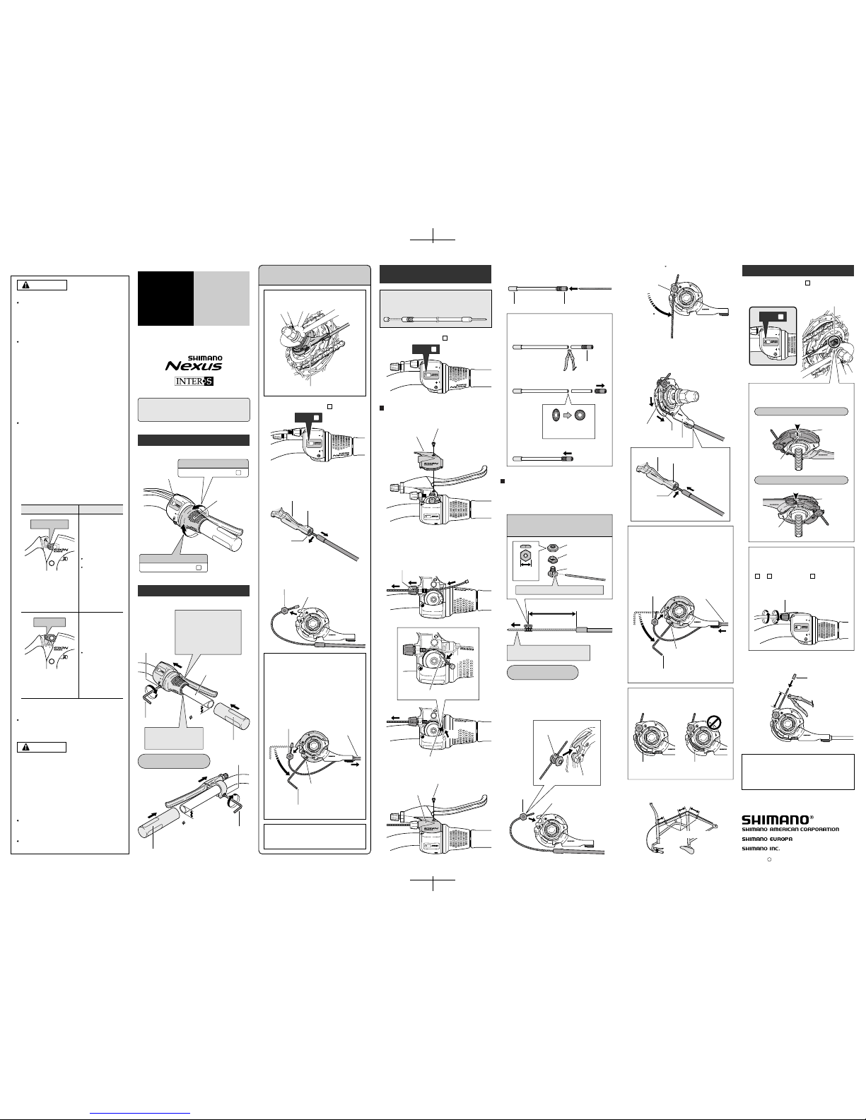
Tighten
Tighten
Handlebar
Half grip
5 mm Allen key
Clamp bolt
22.2 mm
22.2 mm
In case of using Shimano
half grip, the straight
section of the handlebar
should be 166 mm or more
in length; attach the Revoshift lever to this straight
section.
Tightening torque:
6 – 8 Nm {60 – 80 kgfcm}
Leave a gap of 0.5 mm
between the Revo-shift
lever and the half grip.
Installation of the lever
Install the lever as shown in the illustration.
5 mm Allen key
Clamp bolt
Grip
V-Brakes with power
modulator
Cantilever brakes
Roller Brakes
Note:
If reusing the cable, refer to steps 7 to 9 in
"Installation of the shifting cable".
Disconnect the cable from the cassette joint
when removing the rear wheel from the
frame.
1
Set the Revo-shift lever to .
1.
Pull the outer casing out from the outer
casing holder of the cassette joint, and then
remove the inner cable from the slit in the
bracket.
2.
Remove the inner cable fixing bolt unit from
the cassette joint pulley.
3.
Disconnecting the shifting cable when
removing the rear wheel from the frame
Cassette joint
Inner cable fixing bolt unit
Cassette joint pulley
Remove from
the slit
Pull out from outer
casing holder
Bracket
Slit
Set to
1
If it is difficult to pull the outer casing out
from the outer casing holder of the cassette
joint, insert a 2 mm Allen key or a #14
spoke into the hole in the cassette joint
pulley, and then turn the pulley to loosen
the inner cable. Then remove the inner
cable fixing bolt unit from the pulley first,
and after this remove the outer casing from
the outer casing holder.
Outer casing holder
CJ-8S20
JAPAN
2
1
Installation of the shifting
cable
Use a shifting cable with one inner cable drum.
Cable with one inner cable drum /
SIS-SP40 (4 mm dia.)
1.
Set to
1
Cover fixing screw
Upper cover
Hole in cable adjustment bolt
Loosen the cover fixing screw, and then remove
the upper cover.
2.
Pass the inner cable through the hole in the cable
adjustment bolt. Next, hook the inner cable into
the groove of the pulley, and pull the inner cable
so that the inner cable drum fits into the hole in
the pulley.
3.
Revo-shift lever side
Groove in pulley
Hole in pulley
Cover fixing screw
Upper cover
Replace the upper cover and tighten the cover
fixing screw.
4.
101 mm
Gap in pulley
Bring the cable around to the cassette joint pulley,
hold so that the inner cable fixing nut is facing to
the outside (toward the fork end), and then slide
the flats part of the inner cable fixing washer into
the gap in the pulley.
Flats part of inner
cable fixing washer
Inner cable
fixing nut
Pulley
6.
After checking that the end of the outer casing is
sitting securely in the cable adjustment bolt of the
Revo-shift lever, attach the inner cable fixing bolt
unit to the inner cable.
Cassette joint side
Inner cable fixing bolt unit
10 mm
Note: Do not use this inner cable fixing bolt
unit with the CJ-4S30 cassette joint.
Inner cable fixing nut
Inner cable fixing
washer
(Black)
Inner cable fixing bolt
Pass the inner cable through the hole.
Pull the inner cable while attaching
the inner cable fixing bolt unit.
Tightening torque:
4 – 6 Nm {40 – 60 kgfcm}
Pulley
Bracket
Guide
9.
OK Not OK
Secure the cable to the frame with the outer
casing bands.
10 cm
10 cm
15 cm
Turn the
cable 60
Hook
8.
Turn the cable 60 counterclockwise and attach it
to the hook.
Attach the inner cable to the pulley as shown in
the illustration, pass the inner cable through the
slit in the cassette joint bracket, and then insert
the end of the outer casing securely into the outer
casing holder.
Inner cable
Slit
Outer casing holder
Pass through
the slit.
Note:
Check that the inner cable is correctly seated
inside the pulley guide.
If first inserting the outer casing into the
outer casing holder is easier, then first insert
the outer casing into the outer casing holder,
and then insert a 2 mm Allen key or a #14
spoke into the hole in the cassette joint
pulley, and then turn the pulley so that the
inner cable fixing bolt unit fits into the gap in
the pulley.
Hole in pulley
Insert into the
outer casing
holder
Insert the inner cable
fixing bolt unit
Guide
Outer casing bands
Bracket
Insert into the
outer casing
holder.
2 mm Allen key
or #14 spoke
Turn the
pulley
These service instructions explain how to use and
maintain the Shimano bicycle parts which have been
used on your new bicycle. For any questions regarding
your bicycle or other matters which are not related to
Shimano parts‚ please contact the place of purchase or
the bicycle manufacturer.
Adjusting the cassette joint
Set the Revo-shift lever to .
Check to be sure that the yellow setting lines on
the cassette joint bracket and pulley are aligned at
this time.
After adjusting the cassette joint, cut off the
excess length of inner cable and then install the
inner end cap.
4
Inner end cap
Cable adjustment bolt
Cassette joint
pulley
Cassette joint
pulley
Yellow setting lines
15 – 20 mm
Should be straight
Should be straight
When bicycle is upside down
When bicycle is standing up
If the yellow setting lines are not aligned,
turn the cable adjustment bolt of the Revoshift lever to align the setting lines. After this,
move the Revo-shift lever once more from
to and then back to , and then
re-check to be sure that the yellow setting
lines are aligned.
These service instructions are printed on recycled paper.
Please note: Specifications are subject to change for
improvement without notice. (English)
The yellow setting lines on the cassette joint
are located in two places. Use the one that
is easiest to see.
2.
1.
Cassette joint bracket
Cassette joint bracket
Set to
4
Pass the inner cable through the SIS-SP40 outer
casing through the end with the plastic cap.
If cutting the outer casing, cut it near the end
with the plastic cap while the cap is still
attached. Then make the cut end perfectly
round and attach the plastic cap.
(Lever side)
Remove the plastic cap.
Make the cut end
perfectly round.
Attach the plastic cap.
Aluminum cap
Plastic cap
Plastic cap
1
Set the Revo-shift lever to .
4 41
One Holland Irvine CA 92618 U.S.A. Phone 949-951-5003
Industrieweg 24 NL-8071 CT Nunspeet‚ Holland Phone 31-341-272222
3-77 Oimatsucho‚ Sakai‚ Osaka‚ Japan Phone 072-223-3243
Turn the Revo-shift lever to shift to each of the eight
gears.
Mar. 2003 by Shimano Inc. PIT. SZK. Printed in Japan
C
 Loading...