

Clip nut
Brake arm
Brake arm clip
Clip screw
(M6 16 mm)
2 – 3 mm
Non-turn washer
Washer
Cap nut
CJ-NX10
JAPAN
LOCK
CJ-NX10
JAPAN
LOCK
7R
Non-turn washer
Cap nut
7R
CJ-NX10
JAPAN
LOCK
7R
CJ-NX10
JAPAN
Hub axle
Fork end
CJ-NX10
JAPAN
CJ-NX10
JAPAN
CJ-NX10
JAPAN
CJ-NX10
JAPAN
Note the
direction
Snap ring
Sprocket
Right hand
dust cap C
Driver
Brake unit fixing nut
Chainstay
Brake arm
Brake arm clip
SI-7R45E
SG-7R46
SG-7R45
CJ-NX10
General Safety Information
– To avoid serious injuries:
NOTE:
You can shift gears while pedaling, but on rare occasions
the pawls and ratchet inside the hub may produce some
noise afterwards as part of normal gear shifting operation.
The CJ-NX10 cassette joint should only be used with
sprockets from 16T to 23T.
If the wheel becomes stiff and difficult to turn, you should
lubricate it with grease.
Do not apply any lubricant to the inside of the hub,
otherwise the grease will come out.
You should periodically wash the sprockets in a neutral
detergent and then lubricate them again. In addition,
cleaning the chain with neutral detergent and lubricating it
can be a effective way of extending the useful life of the
sprockets and the chain.
If the chain keeps coming off the sprockets during use,
replace the sprockets and the chain.
Parts are not guaranteed against natural wear or
deterioration resulting from normal use.
For maximum performance we highly recommend
Shimano lubricants and maintenance products.
For any questions regarding methods of handling or
adjustment, please contact the place of purchase.
When securing the brake arm to the frame, be sure to
use a brake arm clip that matches the size of the
chainstay, and securely tighten them with the clip screw
and clip nut to the specified tightening torque.
Use a lock nut with a nylon insert (self-locking nut) for the
clip nut. It is recommended that standard Shimano parts
be used for the clip screw, clip nut and brake arm clip.
In addition, use a brake arm clip that matches the size of
the chainstay.
If the clip nut comes off the brake arm, or if the clip screw
or brake arm clip becomes damaged, the brake arm may
rotate on the chainstay and cause the handlebars to jerk
suddenly, or the bicycle wheel may lock and the bicycle
may fall over, causing serious injury.
When installing the hub to the frame, be sure to install
the correct non-turn washers to the left and right sides,
and securely tighten the hub nuts to the specified
torques. If the non-turn washers are installed to one side
only, or if the hub nuts are not tightened sufficiently, the
non-turn washer may fall out, which could cause the hub
axle to rotate and the cassette joint to turn. This may
then cause the handlebars to be accidentally pulled by
the shifting cable, and an extremely serious accident
could result.
Obtain and read the service instructions carefully prior to
installing the parts. Loose, worn, or damaged parts may
cause serious injury to the rider.
We strongly recommend only using genuine Shimano
replacement parts.
Check that the wheels are fastened securely before
riding the bicycle. If the wheels are loose in any way,
they may come off the bicycle and serious injury may
result.
Read these Technical Service Instructions carefully, and
keep them in a safe place for later reference.
Technical Service Instructions
Inter-7 Hub
Cassette joint
Be sure to read these service instructions in conjunction
with the service instructions for the Inter-M Brake and the
Inter-7 shifting lever before use.
WARNING
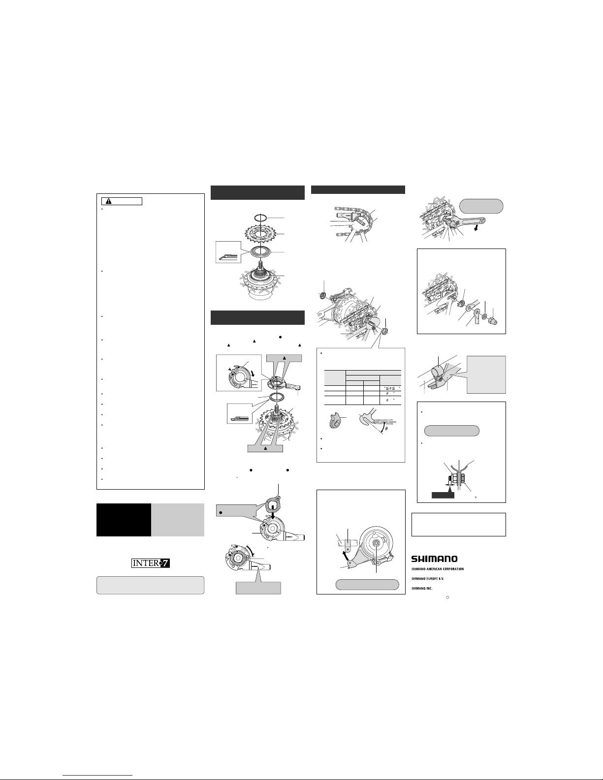
Place right hand dust cap C onto the driver on the right side
of the hub body. Next, install the sprocket and secure it in
place with the snap ring.
Secure the cassette joint to the hub with the cassette
joint fixing ring. When installing the cassette joint fixing
ring, align the yellow
mark with the yellow mark on
the cassette joint pulley, and then turn the cassette joint
fixing ring 45
clockwise.
Installation of the sprocket to the
hub
When installing the brake arm clip, securely
tighten the clip screw while holding the clip nut
with a 10 mm spanner.
Note:
After installing the brake arm clip, check that the
clip screw protrudes about 2 – 3 mm from the
surface of the clip nut.
Take up the slack in the chain and secure the wheel to
the frame with the cap nuts.
Fix the brake arm of the Inter-M brake securely to the
chainstay with the brake arm clip.
Brake arm clip
Chainstay
Brake arm
Note:
When installing a part such as a mudguard stay to
the hub axle, install in the order shown in the
illustration below.
If excessive force is
applied to the brake
arm, the wheel will
become difficult to
turn. Make sure that
you don't apply
excessive force
when installing.
Install the brake arm of the Inter-M brake to the
chainstay with the brake arm clip, provisionally tighten
the clip screw and clip nut, and then tighten the brake
unit fixing nut.
Tightening torque:
20 – 25 N·m {174 – 217 in. lbs.}
Tightening torque:
2 – 3 N·m {17 – 26 in. lbs.}
Note:
If the brake arm is in the incorrect position as shown
in the illustration so that it cannot be provisionally
installed to the chainstay, loosen the brake unit
fixing nut and turn the brake arm. Then, after
provisionally securing the brake arm to the
chainstay, tighten the brake unit fixing nut.
Tightening torque:
30 – 45 N·m
{260 – 390 in. lbs.}
Installation of the cassette joint to
the hub
1.
Install the driver cap to the driver to the right side of the
hub body. Next, turn the cassette joint pulley in the
direction of the arrow so that the yellow
mark is
aligned with the yellow
mark, and then align the
yellow
marks on the cassette joint with the yellow
marks on the right side of the hub body.
Pulley
Should be
aligned
Note the
direction
Driver cap
2.
3.
Turn 45
Fit the cassette joint
bracket securely.
Cassette joint pulley
Cassette joint fixing ring
Cassette joint
Groove of fork end
Chainstay
Non-turn washer
(for right side)
Installation of the hub to the frame
Mount the chain on the sprocket, and then set the hub
axle into the fork ends.
The projecting parts should be on the fork
end side.
Install the non-turn washers so that the
projecting parts is securely in the fork end
grooves on either side of the hub axle.
Different types of left and right non-turn washers
are available for use with standard and reversed
fork ends. Use whichever non-turn washers are
suitable.
Place the non-turn washers onto the right side and left
side of the hub axle. At this time, turn the cassette joint
so that the projecting parts of the non-turn washers fit
into the grooves of the fork ends. If this is done, the
cassette joint can be installed so that it is almost parallel
to the chainstay.
Mark
2.
1.
4.
5.
Yellow marks
Yellow marks
Cassette joint
Driver
Align the yellow
marks to install.
Left
Fork end
Non-turn washer
Reversed
Standard
7R/Black
6R/Silver
7L/Gray
6L/White
Mark/Color
Size
Right
38
20
Reversed
(full chain case)
5R/Yellow
= 0
= 0
5L/Brown
One Holland, Irvine, California 92618, U.S.A. Phone: +1-949-951-5003
Industrieweg 24, 8071 CT Nunspeet, The Netherlands Phone: +31-341-272222
3-77 Oimatsu-cho, Sakai, Osaka 590-8577, Japan
Sep. 2004 by Shimano Inc. PIT. SZK. Printed in Japan
C
These service instructions are printed on recycled paper.
Please note: Specifications are subject to change for improvement without
notice. (English)
These service instructions explain how to use and maintain
the Shimano bicycle parts which have been used on your
new bicycle. For any questions regarding your bicycle or
other matters which are not related to Shimano parts‚ please
contact the place of purchase or the bicycle manufacturer.
Cassette joint fixing ring
Mudguard stay
Carrier stay
Non-turn washer (for left side)
 Loading...