

Page 1

UM-7HU0C-000
SHIMANO Total Electric Power System
Switch Unit Integrated Type
Cycle Computer
User's Manual
Page 2

CONTENTS
IMPORTANT NOTICE
Important safety information
NOTICE
.......................................................................................................2
Regular inspections before riding the bicycle
Booklet Structure
Names of parts
Notation method for operations ...............................................................................................6
Installing and removing the cycle computer
Basic operation
Turning the power ON/OFF ........................................................................................................7
Viewing the screen .....................................................................................................................8
Battery level indicator .............................................................................................................9
Turning the light ON/OFF .........................................................................................................10
Switching the traveling data display .......................................................................................11
Display units ...........................................................................................................................11
Resetting the traveling distance ...........................................................................................12
Gear position when starting from a stop [Start mode] ..........................................................12
Making walking and pushing the bicycle easy (walk assist) ..................................................13
......................................................................................2
.........................................................................2
....................................................3
.........................................................................................4
.............................................................................................5
......................................................6
............................................................................................7
External connections
E-TUBE PROJECT ........................................................................................................................15
Items configurable in E-TUBE PROJECT ................................................................................15
Troubleshooting
Gear shifting adjustment with the electronic gear shifting unit [ADJUST] ..........................15
Error/warning indication ..........................................................................................................16
Error indication ......................................................................................................................16
Warning indication ................................................................................................................16
When a problem occurs ............................................................................................................17
................................................................................... 15
......................................................................................... 15
1
Page 3
IMPORTANT NOTICE
WARNING
•
Contact the place of purchase or a distributor for
information on installation, adjustment, and replacement
of the products which are not found in the user's manual.
The dealer's manual for professional bicycle mechanics is
available from our website
(https://si.shimano.com).
•
Please observe the appropriate rules and regulations of
the country, state or region in which you conduct your
business as a dealer.
For safety, be sure to read this “user's
manual” thoroughly before use, follow it
for correct use, and store it so that it can
be referenced at any time.
The following instructions must be observed at all times in
order to prevent personal injury and physical damage to
equipment and surroundings. The instructions are classified
according to the degree of danger or damage which may
occur if the product is used incorrectly.
DANGER
Failure to follow the instructions will result in death or
serious injury.
WARNING
Failure to follow the instructions could result in death or
serious injury.
CAUTION
Failure to follow the instructions could cause personal
injury or physical damage to equipment and surroundings.
Important safety information
This product contains non-replaceable
battery.
Riding precautions
• INGESTION HAZARD:
This product contains
a button cell or coin
battery.
• DE ATH or serious injury
can occur if ingested.
• A swallowed button cell
or coin battery can cause
Internal Chemical Burns
in as little as 2 hours.
• KEEP new and used
batteries OUT OF REACH
of CHILDREN
• Seek immediate medical
attention if a battery
is suspected to be
swallowed or inserted
inside any part of the
body.
•
Remove and immediately recycle or dispose of used
batteries according to local regulations and keep away
from children. Do NOT dispose of batteries in household
trash or incinerate.
•
Even used batteries may cause severe injury or death.
•
Call a local poison control center for treatment
information.
•
The compatible battery type:MS920T FL27E
•
The nominal battery voltage:3 V
•
Non-rechargeable batteries are not to be recharged.
•
Do not force discharge, recharge, disassemble, heat
above 85°C or incinerate. Doing so may result in injury
due to venting, leakage or explosion resulting in
chemical burns.
WARNING
•
Do not disassemble or modify the product. This may
cause the product to not operate correctly, and you may
suddenly fall and be seriously injured.
•
Do not to pay excessive attention to the cycle computer
display while riding.
Doing so may result in an accident.
•
Confirm that the light works before riding.
2
Page 4
Safety precautions
•
Be sure to remove the battery and charging cable before
wiring or attaching parts to the bicycle.
Failure to do so may cause an electric shock.
•
Be sure to follow the instructions provided in the
manuals when installing the product.
It is recommended to use SHIMANO genuine parts only. If
bolts and nuts become loose or the product is damaged,
the bicycle may suddenly fall over, resulting in a serious
injury.
•
Do not leave this product in an extremely high
temperature surrounding environment such as in a closed
vehicle on a hot day, or near a heater. That can result in
an explosion of the incorporated battery or the leakage
of flammable liquid or gas from it.
•
Do not subject this product to extremely low air pressure.
That can result in an explosion of the incorporated
battery or the leakage of flammable liquid or gas from it.
Transporting this product by air is not a problem.
Disposal precautions
•
Observe all federal, state and local environmental
regulations when disposing of this product, because it
incorporates a battery. Disposal of this product into fire
or a hot oven, or mechanically crushing or cutting it can
result in an explosion of the incorporated battery.
CAUTION
Riding precautions
•
Observe the instructions in the manual for the bicycle in
order to ride safely.
Safety precautions
•
Never modify the system.
Doing so may cause a system error.
•
Use the product under the supervision of someone
responsible for safety, and only as instructed.
Do not allow anyone (including children) with reduced
physical, sensual, or mental capacity, or those without
experience or knowledge, to use the product.
•
Do not allow children to play near the product.
NOTICE
Safety precautions
•
If any malfunction or trouble occurs, consult the place of
purchase nearest you.
•
Be sure to attach caps to any unused connectors.
•
For installation and adjustment of the product, consult
the place of purchase.
•
The components are designed to be fully waterproofed
to withstand wet weather riding conditions; however, do
not deliberately place them into water.
•
Do not clean the bicycle with a high-pressure washer. If
water gets into any of the components, operating
problems or rusting may result.
•
Do not turn the bicycle upside down. There is a risk of
damage to the cycle computer and switch unit.
•
Handle the components carefully, and avoid subjecting
them to strong shock.
•
Although the bicycle still functions as a normal bicycle
even when the battery is removed, the light will not turn
on if it is connected to the electric power system. Be
aware that using the bicycle under these conditions will
be considered non-observance of the road traffic laws in
Germany.
Connection and communication with PC
A PC linkage device can be used to connect a PC to the
bicycle (system or components), and E-TUBE PROJECT can be
used to carry out tasks such as customizing single
components or the whole system and updating firmware.
•
PC linkage device: SM-PCE1/SM-PCE02
•
E-TUBE PROJECT: PC application
•
Firmware: Software inside each component
Care and maintenance
•
Contact the place of purchase for updates of the
component software. The most up-to-date information is
available on the SHIMANO website.
•
Do not use thinner or other solvents to clean any of the
components. Such substances may damage the surface.
•
For any questions regarding methods of installation and
maintenance, please contact your place of purchase.
•
Products are not guaranteed against natural wear and
deterioration from normal use and aging.
•
For maximum performance we highly recommend
SHIMANO lubricants and maintenance products.
Labels
•
Some of the important information contained in this
user's manual is also indicated on the device label.
3
Page 5
Regular inspections before
riding the bicycle
Before riding the bicycle, check the following items. If any
problems are found, consult your place of purchase or a
distributor.
•
Does the drive train perform gear shifting smoothly?
•
Are the components fixed securely and free from
damage?
•
Are the components securely installed to the frame/
handlebar/stem, etc. ?
•
Do any abnormal noises occur while riding?
•
Is there sufficient charge remaining in the battery?
Booklet Structure
SHIMANO STEPS user's manuals are split among
several booklets, as described below.
Be sure to read these user's manuals thoroughly before use,
and follow them for correct use. Store the user's manuals so
that they can be referenced at any time.
The latest user's manuals are available on our website
(https://si.shimano.com).
•
SHIMANO STEPS user's manual
This is the basic user's manual for SHIMANO STEPS. It
contains the following content.
-
SHIMANO STEPS quick guide
-
How to operate assist bicycles that use flat
handlebars, such as city, trekking, or MTB type
bicycles
-
Troubleshooting
•
SHIMANO STEPS user's manual for drop
handlebar bicycles (separate booklet)
This booklet describes how to operate assist bicycles that
use a drop handlebar and are controlled using a dual
control lever. This should be read along with the
SHIMANO STEPS user's manual.
•
SHIMANO STEPS special battery and parts user's
manual
It contains the following content.
-
How to charge and handle the SHIMANO STEPS
special battery
-
How to attach and remove the SHIMANO STEPS
special battery to the bicycle
-
How to use the satellite power button and satellite
charging port
-
How to read the battery LEDs when charging or
during an error, and how to handle errors
•
Cycle computer user's manual (this document)
It contains the following content.
-
Basic operations of the cycle computer and how to
configure settings
-
Wireless communication method (supported models
only)
-
Cycle computer troubleshooting
•
Switch unit user's manual
This is the assist switch and shifting switch user's manual.
It describes switch unit operations.
This symbol on your product, literature,
or packaging reminds you that this
product must be taken to separate
collection at the end of its working life.
Do not dispose of this product as
unsorted municipal waste but instead
take it for recycling. By ensuring the
product is disposed correctly, you will
help to prevent potential negative
consequences for the environment and
human health. For info on your nearest
recycling point, check with your local
waste authority.
4
Page 6
Names of parts
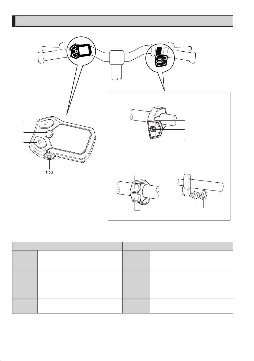
Switch unit integrated type
cycle computer
3-type switch switch unit (right)
X
A
Y
2-type switch
switch unit (right)
Light button
X
Y
The operation for each button is indicated below.
Switch unit integrated type cycle computer Switch unit (right)
Increase assistance
Button-X
Button-Y
Button-A Switching traveling data display Button-A*1
When in walk assist mode: Disengage walk
assist mode *2
Decrease assistance
Hold down: Switch to walk assist mode *2
When in walk assist mode: Activate walk
assist *2
Button-X Shi
Button-Y Shi
fting up
fting down
Switch between automatic and manual gear
shifting
X
A
Y
MTB type
switch unit (right)
X Y
*1 Only enabled when the assist bicycle supports automatic gear shifting.
*2 Depending on the region of use, you may not be able to use it due to the laws of the region. Refer to “Making walking
and pushing the bicycle easy (walk assist)” for details on walk assist mode.
5
Page 7
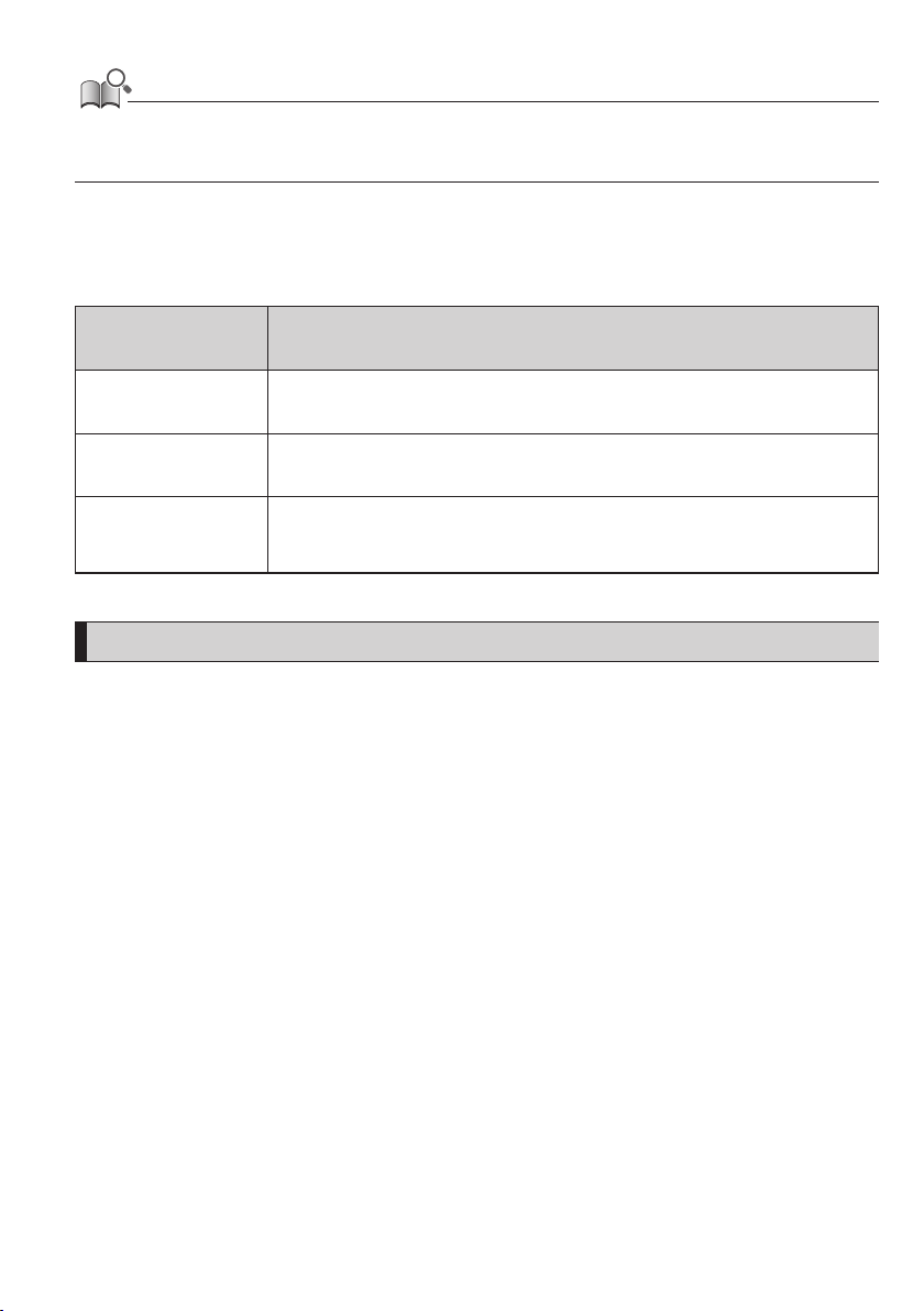
• When connected to the E-TUBE PROJECT, you can change the functions assigned to each button on the switch unit. Please contact your
place of purchase for details.
• The button layout may differ according to the switch unit. Refer to the “Switch unit user's manual” for details.
Notation method for operations
Subsequent operations using the main body button and switch unit of this product are indicated using the following
notation.
Notation Operation
<X> Indicates an operation for pressing button-X of the cycle computer.
<A> Indicates an operation for pressing button-A of the cycle computer.
[AUTO]
(Example) Auto gear
shifting
Items displayed on the cycle computer screen are enclosed in square brackets in this
manual.
Installing and removing the cycle computer
For the installation/removal procedure, contact your place of purchase or the distributor.
6
Page 8
Basic operation
Turning the power ON/OFF
The power of this product is linked with the main power of the assist bicycle. When the main power is turned ON, all
components connected to the drive unit of the assist bicycle are also turned ON (such as assist driving, the power of this
product, the electronic gear shifting mechanism, and the lights).
For the procedure for turning the main power ON/OFF, refer to the “SHIMANO STEPS user's manual.”
NOTICE
• Before turning the power ON, please refer to the “SHIMANO STEPS special battery and parts user's manual” to check the following.
- The battery is firmly attached to the battery mount
• The power cannot be turned ON while charging.
• If the bicycle is left unused for 10 minutes or more after turning the power ON, the power automatically turns OFF (auto power OFF
function).
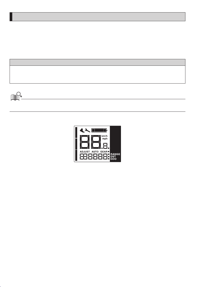
When the main power is turned ON, a screen similar to that shown below is displayed, and then switches to the main screen.
7
Page 9
Viewing the screen
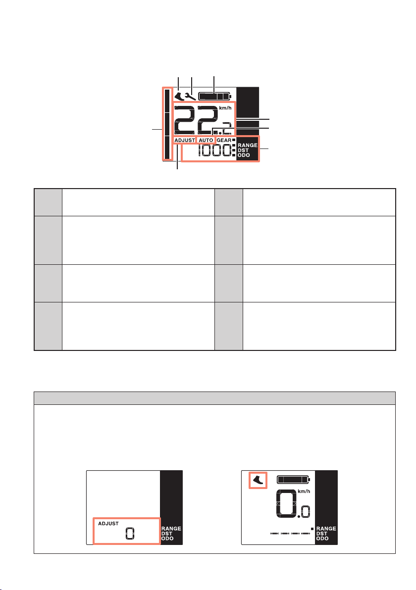
The items displayed on the main screen differ according to the assist bicycle.
Main screen
(H)
(G)
(A)
(F)
(E)
(B)
(C)
(D)
Battery level indicator
(A)
(Refer to “Battery level indicator”)
Current speed
Displays the current speed. (Refer to “Display
(B)
units”)
Auto gear shifting display
(C)
Displayed for the auto gear shifting.
Traveling data display
(D)
(Refer to “Switching the traveling data display”)
*1 Depending on the region of use, you may not be able to use it due to the laws of the region. Refer to “Making walking
and pushing the bicycle easy (walk assist)” for details on walk assist mode.
ADJUST mode display
(E)
(Refer to “NOTICE” below)
Assist gauge
Displays the current assist mode. A mode that
(F)
provides stronger assistance the longer the
length of the displayed gauge.
Walk assist*1
This icon is displayed when switched to walk
(G)
assist mode.
Maintenance alert
Indicates that maintenance is required. Contact
(H)
your place of purchase or a distributor if this
icon is displayed.
NOTICE
If you are unable to change gears using the electronic gear shifting, check the cycle computer display for the following.
•
If [ADJUST] is displayed on the screen, press <A> on the cycle computer to return to the main screen.
•
If the walk assist icon is displayed on the screen, press <X> on the cycle computer to disengage walk assist mode.
•
Refer to “Error/warning indication” also.
Example of ADJUST mode screen Example of walk assist icon display
8
Page 10
Battery level indicator
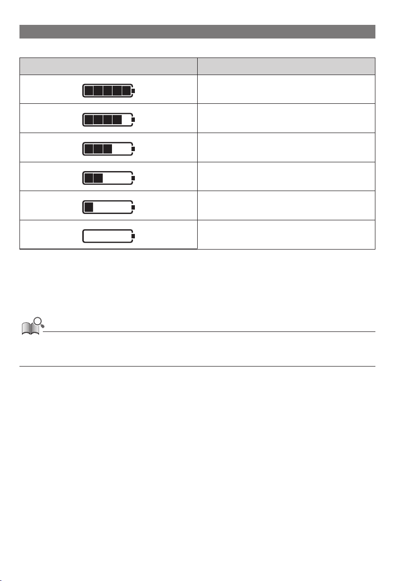
The battery level is shown as an icon.
Display Battery level
100 - 81%
80 - 61%
60 - 41%
40 - 21%
20 - 1% *
0%
*
The battery level indicator will flash when the battery level is low if the assist mode is set to something other than
[OFF].
• The cycle computer uses zero to indicate a battery level where assistance cannot be performed. With the SHIMANO STEPS system, the light
can still be lit up for a while when assist stops due to a low battery. Therefore, the above-mentioned battery level may differ from that
which can be checked on the battery.
9
Page 11
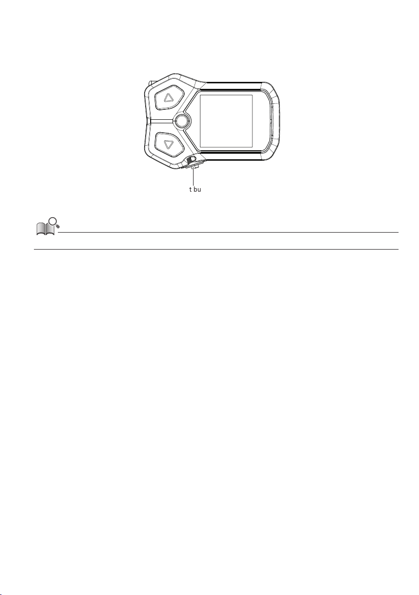
Turning the light ON/OFF
If a light is connected to the drive unit, this product can be used to operate the light.
1.
Press the light button.
Light button
• The light power is linked with the main power. The light cannot be turned ON when the main power is OFF.
10
Page 12
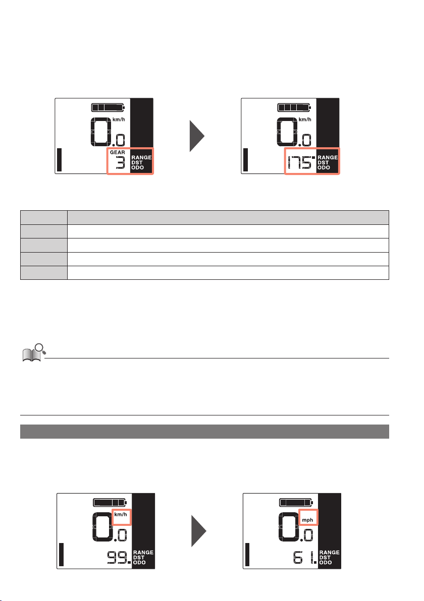
Switching the traveling data display
On the main screen, you can check various traveling data in addition to the current speed. The traveling data that can be
displayed differs according to the assist bicycle.
1.
On the main screen: Press <A>.
Current gear position Traveling range
The traveling data switches in the following order each time <A> is pressed.
Display item Explanation
[GEAR] Current gear position*1
[RANGE] Traveling range*2
[DST] Traveling distance
[ODO] Cumulative distance
*1 Only displayed for electronic gear shifting.
*2 The traveling range (reference value) for the selected assist mode. The display switches each time the assist mode is
switched. The value is not displayed when the assist mode is set to [OFF].
• If the traveling data display is switched when [ODO] is displayed, the screen will switch back to displaying [GEAR] (for electronic gear
shifting) or [RANGE] (for mechanical gear shifting).
• The traveling data display condition that was last displayed is retained even when the power is turned OFF.
• Even when the traveling data display is switched to something other than [GEAR], the screen will switch to displaying [GEAR] for
approximately two seconds when a gear shift operation is performed.
Display units
This product can switch the display units of speed, traveling distance, and cumulative distance to km or miles. It is
necessary to connect to E-TUBE PROJECT (PC version) to switch the display units. For the connection method and setting
procedure, contact your place of purchase.
Displayed in km Displayed in miles
11
Page 13
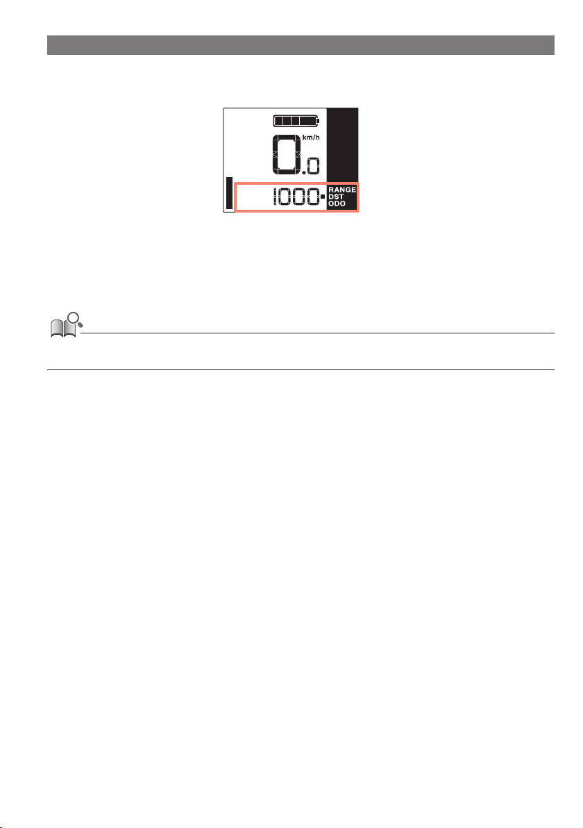
Resetting the traveling distance
The traveling distance is reset from the main screen.
1.
On the main screen: Press <A>. (Switches the traveling data display to [DST])
2.
Hold down <A>. (Continue to hold down until the number displayed for [DST] flashes)
3.
When the number displayed for [DST] is flashing: Press <A>.
The traveling data is reset.
• If nothing is done for five seconds after the number for [DST] begins flashing, it will stop flashing and the screen will return to the main
screen. The display will automatically return to the main screen when the start of traveling is detected.
Gear position when starting from a stop [Start mode]
The assist bicycle where this product is installed may be set to automatically switch to a gear where it is easier to start riding
again after stopping. If you want to change this setting, contact your place of purchase.
12
Page 14
X
Y
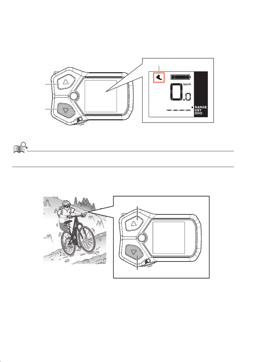
Making walking and pushing the bicycle easy (walk assist)
Depending on the region of use, you may not be able to use it due to the laws of the region. In this case, the operations
described here are disabled.
1.
Stop and switch to walk assist mode.
Hold down button-Y until it reaches the following state.
Walk assist icon
• If nothing is done for one minute after switching to walk assist mode, it will switch back to the assist mode that was selected before
switching.
2.
Push the bicycle carefully while pressing the same button again.
If you let go of button-Y, the assist stops.
X
Y
13
Page 15
NOTICE
X
Y
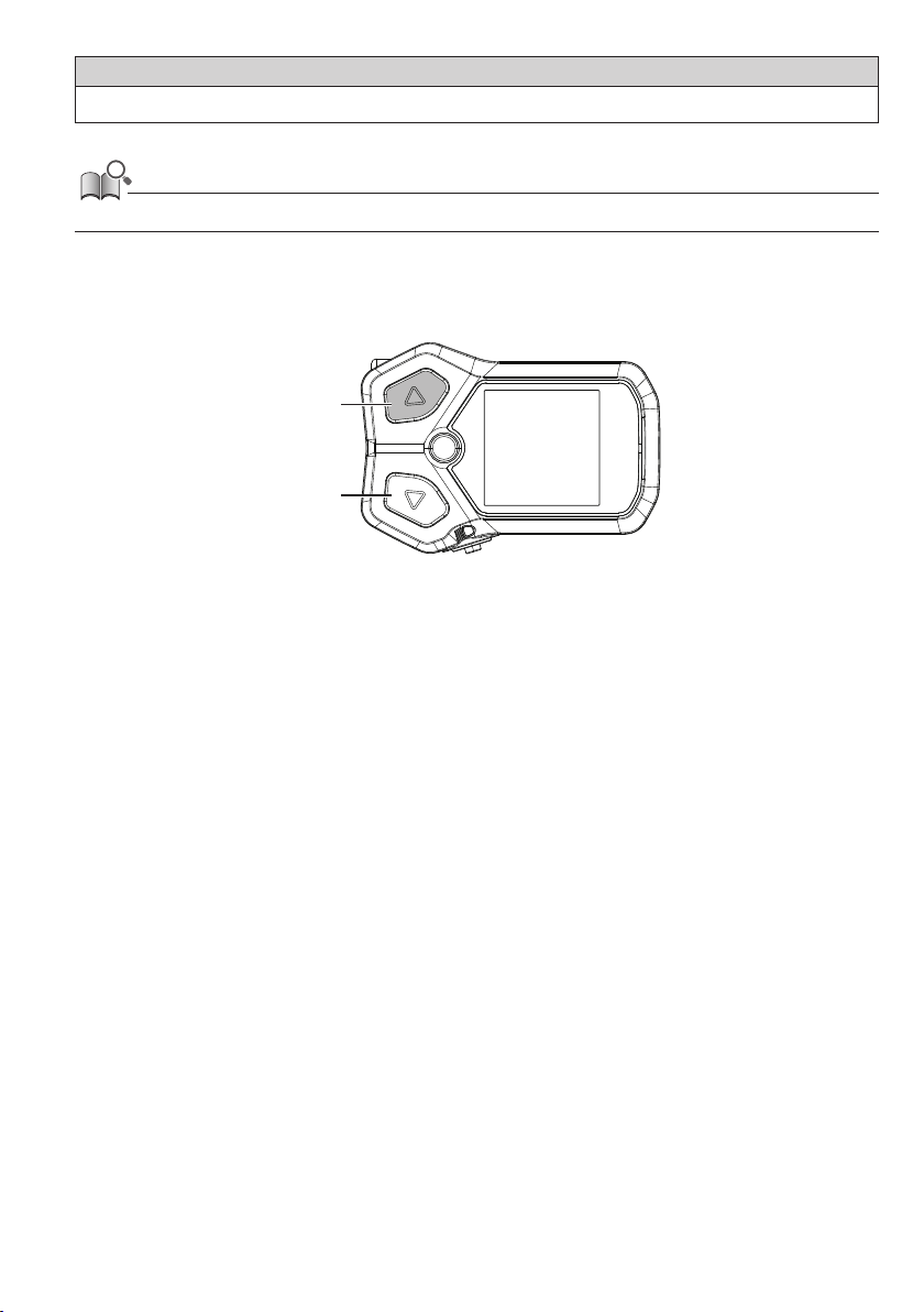
Walk assist operates at a maximum of 6 km/h. Be careful because the bicycle starts moving just by button operations.
• During electronic gear shifting, the assistance of walk assist and speed are controlled by the current gear position.
3.
Exit walk assist mode.
Press button-X.
14
Page 16
External connections
This product has a function for communicating with a PC. For the connection method, contact your place of purchase.
E-TUBE PROJECT
E-TUBE PROJECT is needed to change the setting of the SHIMANO STEPS and to update firmware.
Download E-TUBE PROJECT from our support website (https://bike.shimano.com/e-tube/project.html).
For information on how to install E-TUBE PROJECT, check the support website.
NOTICE
Do not connect to a device while the battery is being charged.
• Firmware is subject to change without notice.
Items configurable in E-TUBE PROJECT
The items that can be set differ according to the assist bicycle. Refer to the user's manual for E-TUBE PROJECT for details.
•
You can change the functions assigned to each operation switch in [Switch setting].
•
You can change the display units for speeds and distances in [Display units].
•
You can set/change the gear when starting from a stop in [Start mode]. (Internal electronic gear shifting only)
•
You can select to have the backlight of the display always ON, always OFF, or linked to the light in [Backlight setting].
Troubleshooting
Gear shifting adjustment with the electronic gear shifting unit [ADJUST]
If gear shifting feels abnormal, contact the place of purchase.
15
Page 17
Error/warning indication
Error indication
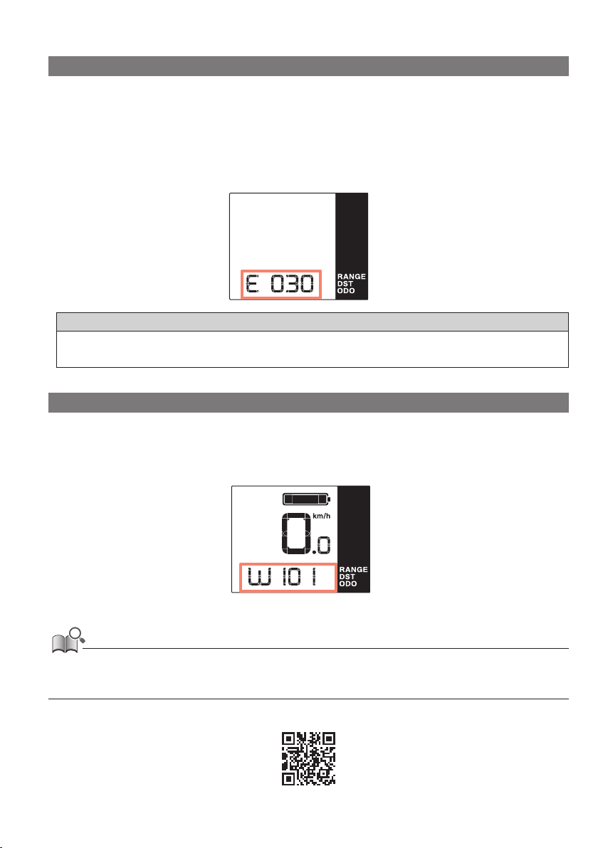
If an error code “E***” (where *** is letters or numbers) is displayed on the entire screen, the product may have
malfunctioned.
Refer to the “SHIMANO STEPS special battery and parts user's manual” and follow one of the procedures below to reset
the display.
•
Press the battery power button to turn the power OFF.
•
Remove the battery from the battery mount.
NOTICE
• If the situation does not improve even after turning the power back ON, consult with the place of purchase or a distributor as soon as
possible.
Warning indication
If a warning code “W***” (where *** is letters or numbers) is displayed on the screen, the product may have a
temporary problem.
If the situation is improved, this indication will disappear. If the situation does not improve, contact the place of
purchase as soon as possible.
• The PC version of E-TUBE PROJECT (V4 or later) classifies errors and warnings into more detailed categories according to the cause. For this
reason, the error and warning codes that are displayed in the PC version of E-TUBE PROJECT may differ from those displayed on this
product, E-TUBE RIDE, or smartphone version of E-TUBE PROJECT.
For details on error/warning codes, check the latest versions below:
https://si.shimano.com/iER/STP0A
16
Page 18

When a problem occurs
Symptoms Possible cause Remedy
Refer to the “SHIMANO STEPS special
battery and parts user's manual” to charge
the battery, and then turn the power ON
again.
Refer the “SHIMANO STEPS special battery
and parts user's manual” to turn the power
ON.
When charging with the battery installed
to a bicycle, you cannot turn the power ON.
Stop charging.
Check whether the connector of the electric
wire is disconnected. If you are not sure,
contact the place of purchase.
Contact the place of purchase.
Check whether the connector of the electric
wire is disconnected. If you are not sure,
contact the place of purchase.
It is necessary to connect to E-TUBE
PROJECT to disable or change the setting of
[Start mode]. Contact the place of
purchase.
Pressing the pedal gently makes it easier to
shift gears.
The cycle computer screen
does not light up when the
(main) battery power
button is pressed.
The gear position is not
displayed.
The gear shifts by itself
when the bicycle starts from
a stop.
The gear position set in
[Start mode] is not set when
the bicycle is stopped.
The (main) battery level may be too low.
Is the power ON?
Is the battery charging?
Is the connector of the electric wire
installed correctly?
A product that the system cannot identify
may be connected.
The gear position is only displayed when
the electronic gear shifting unit is installed.
On bicycles with internal electronic gear
shifting specifications, the bicycle may be
set in advance to automatically switch to a
gear where it is easy to start from a stop
([Start mode]).
You may have pressed the pedal too
strongly.
17
Page 19

One Holland, Irvine, California 92618, U.S.A. Phone: +1-949-951-5003
High Tech Campus 92, 5656 AG Eindhoven, The Netherlands Phone: +31-402-612222
Roebuck Way, Knowlhill, Milton Keynes, Buckinghamshire, MK5 8HL, United Kingdom
3-77 Oimatsu-cho, Sakai-ku, Sakai City, Osaka 590-8577, Japan
Please note: specifications are subject to change for improvement without notice. (English)
© Mar. 2024 by SHIMANO INC. ITP
 Loading...