

Shimano RD-TX35,RD-TX55,RD-TX75 Technical Service Instructions
TOURNEY Rear Derailleur
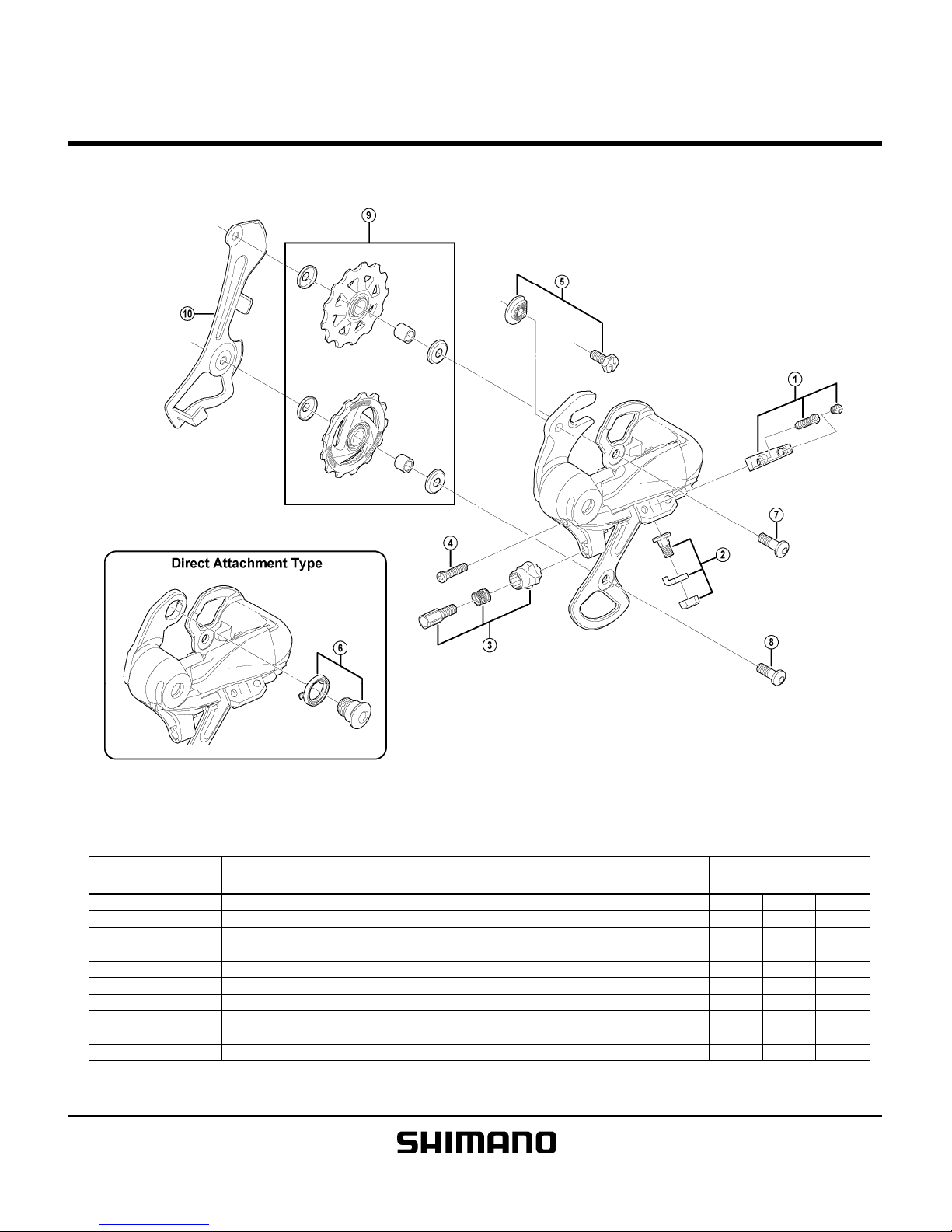
RD-TX35
ITEM
NO.
1 Y5WS98010 Stroke Adjusting Screws (M4 x 15.3) & Plate
2 Y5WG98010 Cable Fixing Bolt Unit A
3 Y5V898030 Cable Adjusting Bolt Unit A
4 Y5T822100 B-Tension Adjusting Screw (M4 x 17.5) A
5 Y54M98030 Adapter Bolt (M5 x 11.5) & Nut A
6 Y5WS98020 B-Axle & Spacer (Direct Attachment Type)
7 Y5TW35010 Guide Pulley Bolt (M5 x 15.2)
8 Y5TW35040 Tension Pulley Bolt (M5 x 13.35)
9 Y5WS98030 Guide & Tension Pulley Unit
10 Y5WS09000 Inner Plate
A: Same parts. Jul.-2010-3100
B: Parts are usable, but differ in materirals, appearance, finish, size, etc.
©
Shimano Inc.
A
Absence of mark indicates non-interchangeability.
Specifications are subject to change without notice.
INTERCHANGEABILITY
SHIMANO
CODE NO.
DESCRIPTION
R
D
-
M
3
6
0
R
D
-
T
X
3
1
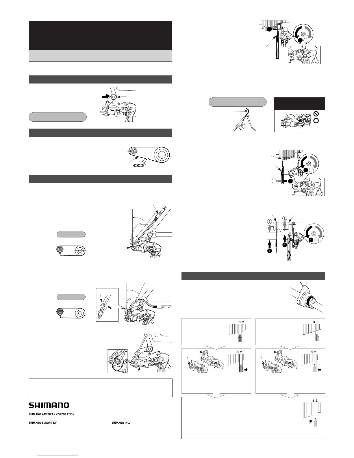
•If routing the casing upward:
(The chain should be on the largest chainring and on the
largest sprocket.)
Add 10 mm to the length of the outer casing from the end
that is inserted into the outer casing holder to the end
which is inserted into the link.
•If routing the casing downward:
(The chain should be on the largest chainring and on the largest sprocket.)
Set the length of the outer casing so that it describes a smooth arc, and so that the
link stops in a position where there is a small gap between the link and the link stop.
Rear derailleur
Adjustment Method
RD-TX75/RD-TX55/RD-TX35
Te chnical S er v i ce I n s tr u c tions
SI-5WU0A-001
Loosen the outer casing adjustment
barrel until the chain touches the 3rd
sprocket and makes noise. (counter
clockwise)
Tighten the outer cable adjusting barrel
until the chain returns to the 2nd
sprocket. (clockwise)
Best setting
The best setting is when the shifting lever is operated just enough to
take up the play and the chain touches the 3rd sprocket and makes
noise.
*Return the lever to its original position (the position where the lever
is at the 2nd sprocket setting and it has been released) and then turn
the crank arm clockwise. If the chain is touching the 3rd sprocket
and making noise, turn the outer casing adjustment barrel clockwise
slightly to tighten it until the noise stops and the chain runs smoothly.
Mount the chain on the smallest chainring
and the largest sprocket, and turn the crank
arm backward. Then turn the B-tension
adjustment screw to adjust the guide pulley
as close to the sprocket as possible but not
so close that it touches. Next, set the chain
to the smallest sprocket and repeat the
above to make sure that the pulley does not
touch the sprocket.
Operate the shifting lever several times to move the chain to the
2nd sprocket. Then, while pressing the lever just enough to take
up the play in the lever, turn the crank arm.
SIS Adjustment
B-tension
adjustment screw
Largest sprocket Smallest sprocket
1
2
1 2
Guide pulley
Largest
sprocket
Pull
Groove
Note: Be sure that the cable is
securely in the groove.
Tightening torque:
5 - 7 N·m {44 - 60 in. lbs.}
2. Connection and securing of cable
Connect the cable to the rear derailleur and, after taking up the initial slack in the
cable, reattach to the rear derailleur as shown in the illustration.
Secure the cable by pulling it with pliers with a force of 5 - 10 kg.
3. Low adjustment
Turn the low adjustment screw so that the
guide pulley moves to a position directly
below the
largest sprocket.
4. How to use the B-tension adjustment screw
For the best SIS performance, periodically lubricate all power-transmission parts.
When shifting to 3rd
Play
When no sound at all is
heard
Chain length
Add 2 links (with the chain on both the largest
sprocket and the largest chainring)
Chain
Large
chainring
Largest
sprocket
Cable securing and stroke adjustment
Installation of the rear derailleur
Push in and
tighten
Tightening torque:
8 - 10 N·m {70 - 86 in. lbs.}
5 mm Allen Key
Place the outer casing so that it does not touch the basket and mudguard, otherwise it
may cause a problem with the performance of the derailleur.
Set the outer casing (RD-TX75/RD-TX55) so that its length is as follows.
Outer casing holder
Link
Largest
sprocket
Largest
chainring
Link stop
Link
Chain position
Largest
sprocket
Largest
chainring
Chain position
L
Connect the inner cable to the derailleur as shown in the
illustration.
Inner cable
1. Top adjustment
Turn the top adjustment screw to adjust so
that the guide pulley is below the outer line
of the smallest sprocket when looking from
the rear.
max.
angle
max.
angle
One Holland, Irvine, California 92618, U.S.A. Phone: +1-949-951-5003
Industrieweg 24, 8071 CT Nunspeet, The Netherlands Phone: +31-341-272222
3-77 Oimatsu-cho, Sakai-ku, Sakai-shi, Osaka 590-8577, Japan
* Service Instructions in further languages are available at :
http://techdocs.shimano.com
Please note: specifications are subject to change for improvement without notice. (English)
©Mar. 2010 by Shimano Inc. XBC IZM Printed in Singapore.
This service instruction explains how to use and maintain the Shimano bicycle parts
which have been used on your new bicycle.
For any questions regarding your bicycle or other matters which are not related to
Shimano parts, please contact the place of purchase or the bicycle manufacturer.
1 2
1
2
Guide pulley
Outer line of smallest
sprocket
Top
adjustment
screw
Low adjustment
screw
adjustment
barrel
RD-TX75
RD-TX55
RD-TX35
adjustment
barrel
RD-TX75
RD-TX55
RD-TX35
SI-5WU0A-001-00
 Loading...