

Page 1
SERVICE MANUAL
vol.1
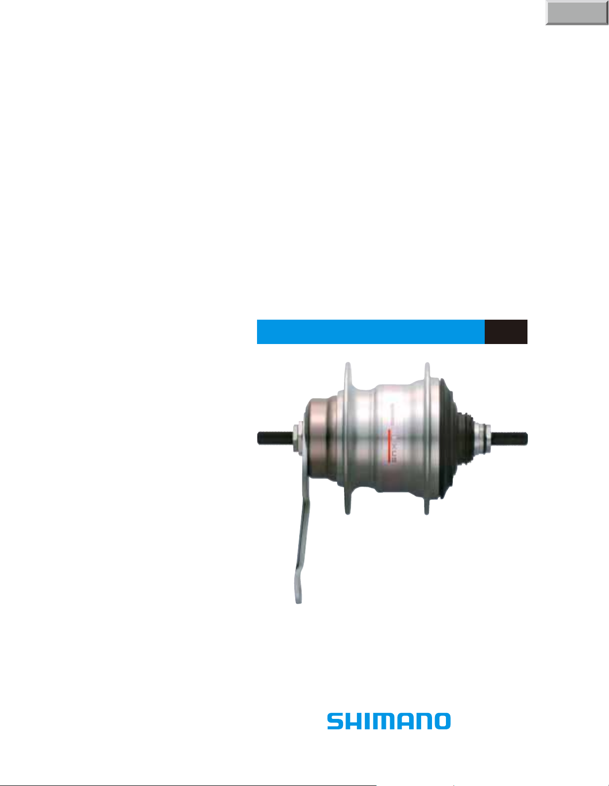
SG-7C26
SHIMANO NEXUS 7-SPEED HUB
t
Page 2
Disassembly of the Inter-7 hub
1.
Hold the two bevelled surfaces
of the hub axle on the brake
arm side in a vice and remove
the dust cap with a screwdriver.
2.
Turn the brake arm unit
upside down and hold
the two bevelled surfaces of
the hub axle on the sprocket
side in a vice.
2
SG-7C26
Tools
Note:
Unit parts should never be
disassembled. If they are,
problems may result.
When replacing parts,
replace the whole internal
assembly or unit part.
Note:
Before carrying out
disassembly, have ready
the hub spanners(TL-7S20)
and internal hub grease.
Note:
Do not damage the threads of
the hub axle.
Vice
Note:
Do not damage
the threads of
the hub axle.
Lock nut
Stop nut
Hub spanners
Part No. 3-130 9890
17mm x 22mm(2 pcs.)
TL-7S20
(Right)
Screwdriver
(Left)
Remove the left hand lock nut
from the hub axle, and then
remove the stop nut.
TL-7S20
Page 3
3
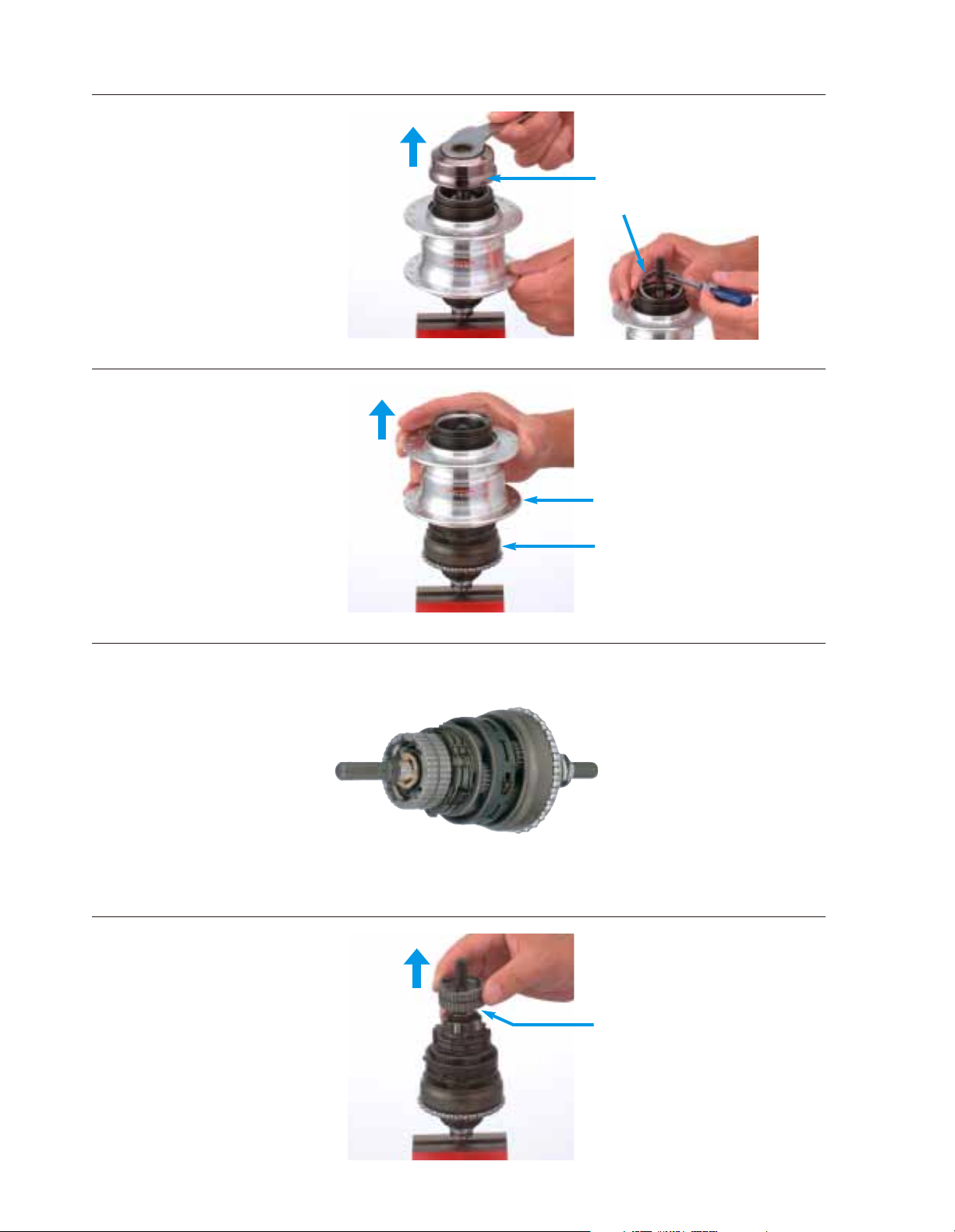
3.
Remove the brake arm unit
and ball retainer B from
the hub axle.
4.
Remove the hub shell.
5.
Remove the brake shoe unit.
Now it can be replaced
with the new internal
assembly.
Disassembly and assembly can
be carried out quickly.
Part No. 33Z 9801
Ball retainer B
Brake arm unit
Internal assembly
Hub shell
Brake shoe unit
Page 4
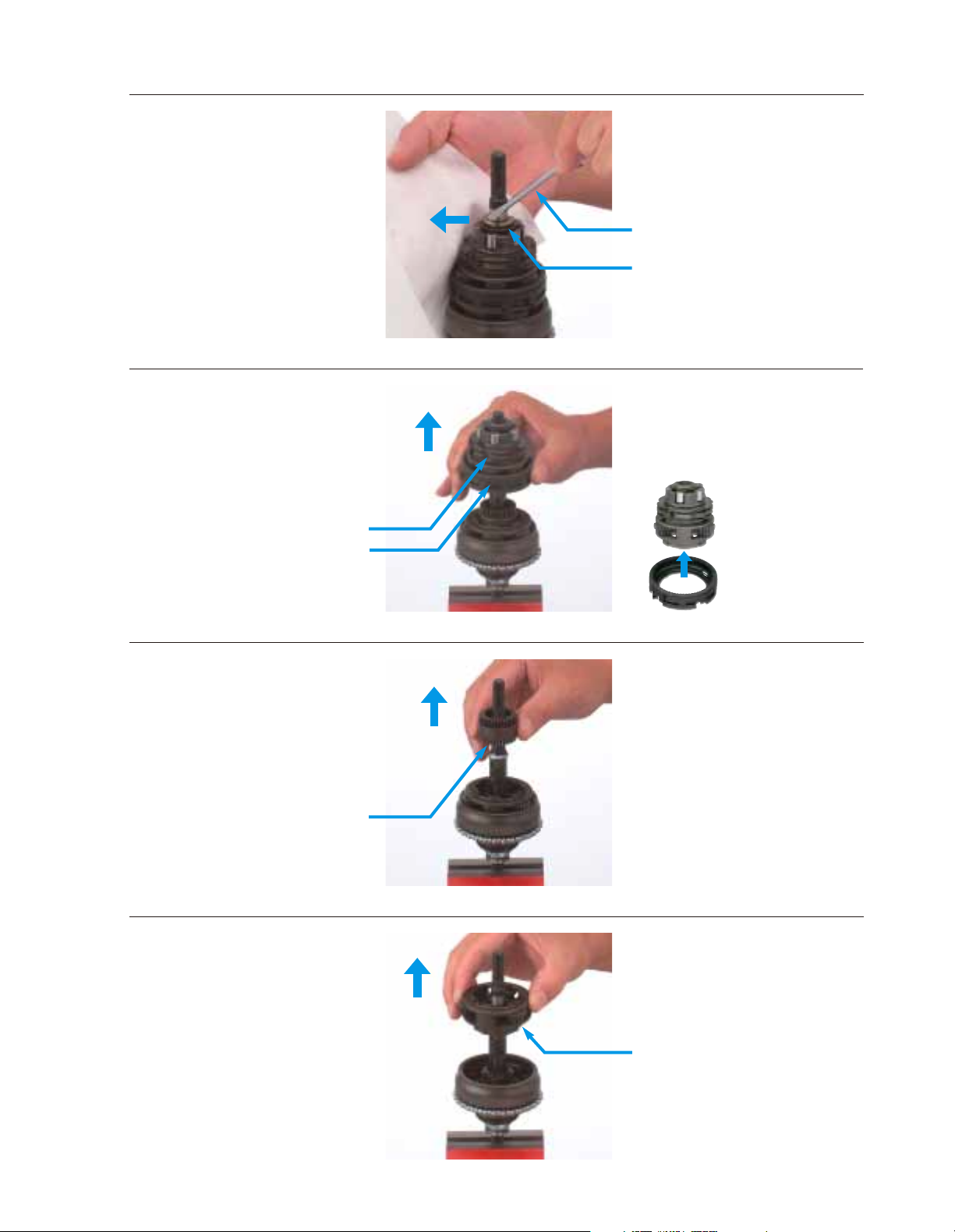
6.
Remove the stop ring with
a screwdriver.
At this time, the stop ring
come off with great force.
Be careful of the safety using
cloth and so on.
Note:
If undue force is applied during
removal, the pawls inside will
become damaged, which will
cause operation problems.
After removing them at the same
time, remove carrier unit 2 from
ring gear unit 2.
7.
8.
Remove sun gear unit 2 and 3
while turning them slightly to
the left and right.
4
9.
Remove carrier unit 1.
Remove ring gear unit 2 and
carrier unit 2 at the same time
while turning ring gear unit 2
slightly to the left and right.
Carrier unit 2
Ring gear unit 2
Carrier unit 1
Stop ring
Screwdriver
Carrier unit 2
Ring gear unit 2
Sun gear unit 2 & 3
Page 5

5
10.
Remove ring gear unit 1 while
turning it slightly to the left
and right.
11.
Remove ball retainer H while
pressing in pawl C on the
driver and axle unit with a
screwdriver.
Be careful not to bend ball
retainer H.
This completes the disassembly
of the Inter-7 hub.
Screwdriver
Ring gear unit 1
Ball retainer H
Pawl C
Page 6

6
Assembly of the Inter-7 hub
2.
Install ball retainer H while
pressing in pawl C on the
driver and axle unit with a
screwdriver.
3.
Insert the end of the slide
spring of ring gear unit 1 into
the wide hole section B of the
driver and axle unit, press in
pawl C (2 places) with a
screwdriver, and then install
ring gear unit 1.
1.
Hold the two bevelled surfaces
of the hub axle on the sprocket
side in a vice.
Note:
Apply a liberal coating of internal
hub grease to the gear inside ring
gear unit 1.
Check:
After installing ring gear unit
1, turn ring gear unit 1 firmly
counterclockwise to check to
be sure that pawl C makes a
clicking sound.
Note:
Do not damage the threads of
the hub axle.
Note:
Be careful of the
setting direction.
Apply a liberal coating of
internal hub grease.
Be careful not to bend ball
etainer H while pressing it.
Be careful not to catch on the end
of return spring C.
(Y-041 20800)
GREASE
(Y-041 20800)
GREASE
Ring gear unit 1
Vice
Screwdriver
Ball retainer H
Wide hole section B
Pawl C
Pawl C
Pawl C
Pawl C
End of slide spring
Page 7

7
5.
Engage the teeth of sun gear
unit 2 and 3 with the teeth of
the planet pinion in carrier
unit 1 while turning sun gear
unit 2 and 3 slightly to the left
and right, and then press in
carrier unit 1.
4.
Engage the teeth of the planet
pinion in carrier unit 1 with
the teeth of ring gear unit 1,
and then press in ring gear
unit 1 while turning it slightly
to the left and right.
Note:
Apply a liberal coating of internal
hub grease to the teeth of sun
gear unit 2 and 3.
Be careful of the setting
direction. If the setting is
reversed, installation
will not be possible.
If undue force is applied,
the pawls inside will become
damaged, which will cause
operation problems.
The gear with the smooth ring
section is at top.
Note:
Apply a liberal coating of internal
hub grease to the planet pinions
(3 places) in carrier unit 1.
6.
Place ring gear unit 2 onto
carrier unit 1.
Note:
Apply a liberal coating of internal
hub grease to the teeth of ring
gear unit 2.
Set so that the part with
the teeth is at the top.
(Y-041 20800)
GREASE
(Y-041 20800)
GREASE
(Y-041 20800)
GREASE
The gear with the smooth
ring section is at top.
Teeth of planet pinion
in carrier unit 1
Teeth of ring gear unit 1
Ring gear unit 2
Carrier unit 1
Sun gear unit 2 & 3
Page 8

8
7.
Engage the teeth of the planet
pinion in carrier unit 2 with
the teeth of ring gear unit 2
while turning carrier unit 2
slightly to the left and right,
and then press in ring gear
unit 2.
Note:
Apply a liberal coating of internal
hub grease to the inside and
outside of the brake shoe unit.
Note:
Apply a liberal coating of internal
hub grease to the grease groove
of the hub shell.
If seal spring R hooks into
the wrong part of the right hand
dust cap, push seal spring R with
a screwdriver.
Check:
After installing the hub shell, turn
the hub shell counterclockwise
and check to be sure that it turns
smoothly.
Note:
Apply a liberal coating of internal
hub grease to the teeth of
the planet pinion (3 places) in
carrier unit 2.
If undue force is applied,
the pawls inside will become
damaged, which will cause
operation problems.
Check:
Check to be sure that the stop
ring groove on the hub axle is
visible from the edge of carrier
unit 2 while carrier unit 2 is
pushed down.
8.
9.
Align the notched section of
the brake shoe unit with
the end of slide spring in
carrier unit 2, and then install
the brake shoe unit.
10.
Install the internal assembly
while turning the hub shell
slightly to the right and left so
that seal spring R of the hub
shell is sitting in the right
hand dust cap of the internal
assembly.
While pushing down carrier
unit 2, insert the stop spring
into the hub axle groove at
the surface of carrier unit 2.
Teeth of planet pinion
in carrier unit 2
Teeth of ring gear unit 2
Hub axle groove
should be visible
Notched section
of the brake shoe unit
End of slide spring
Stop ring
Carrier unit 2
Seal spring R
Grease
groove
Right hand
dust cap
Hub shell
Internal
assembly
(Y-041 20800)
GREASE
(Y-041 20800)
GREASE
(Y-041 20800)
GREASE
Page 9

9
TL-7S20
Lock nut
Stop nut
This completes the assembly
of the Inter-7 hub.
14.
Install the dust cap
11.
Place ball retainer B onto
the hub shell.
Note:
Apply a liberal coating of internal
hub grease to the inside and
outside of the brake shoe unit.
Note:
Be careful of the setting
direction.
Apply a liberal coating of internal
hub grease.
12.
13.
Screw the stop nut to adjust so
that the hub shell can be
turned smoothly without any
play. After adjusting, secure
the stop nut with the lock nut.
Place the brake arm unit onto
the hub axle and turn it to
the left and right so that
the serrations of the brake
shoe and brake arm unit
engage with each other.
Then push the brake arm unit
fully into the brake shoe unit.
Ball retainer B
Hub shell
Brake arm unit
Brake shoe unit
Serrations
(Y-041 20800)
GREASE
(Y-041 20800)
GREASE
Page 10

10
Spare parts list
DESCRIPTIONQ'TY
SHIMANO
CODE NO.
ITEM
NO.
Internal Assembly (Axle Length 175.5 mm)
Brake Shoe Unit
Stop Ring ( 9 mm)
Carrier Unit 2
Ring Gear Unit 2
Sun Gear Unit 2 & 3
Carrier Unit 1
Ring Gear Unit 1
Ball Retainer H (3/16" x 29)
Axle & Driver Unit (Axle Length 175.5 mm)
w/Right Hand Dust Cap B & C
Right Hand Dust Cap B
Right Hand Dust Cap C
Cassette Joint Fixing Ring
Axle Unit (Axle Length 175.5 mm)
Return Spring A
Gear Shifting Cam
Feed Cam
Driver Unit w/Right Hand Dust Cap B & C
Driver Unit
Ball Retainer F (3/16" x 12)
Right Hand Cone w/Seal
Right Hand Cone Seal
Driver Plate w/Seal
Driver Plate Seal
Lock Washer
Stop Washer
Right Hand Lock Nut (3.4 mm)
Cap Nut (3/8")
Non-turn Washer 5R (Yellow)
Non-turn Washer 6R (Silver)
Non-turn Washer 7R (Black)
Non-turn Washer 5L (Brown)
Non-turn Washer 6L (White)
Non-turn Washer 7L (Gray)
Lock Nut (3.5 mm)
Stop Nut
Brake Arm Unit
Ball Retainer B (3/16" x 16)
Sprocket Wheel 18T
Sprocket Wheel 19T
Sprocket Wheel 20T
Sprocket Wheel 21T
Sprocket Wheel 22T
Snap Ring C
CJ-NX10 Cassette Joint Unit
Driver Cap
CJ-NX10 Cassette Joint
Inner Cable Fixing Bolt Unit for CJ-NX10
Brake Arm Clip Unit (5/8")
Brake Arm Clip Unit (3/4")
Clip Screw (M6 x 16)
Clip Nut
TL-7S20 Hub Spanner (17 mm x 22 mm) 2 pcs.
TL-7S40-B Right Hand Cone Tool
Internal Hub Grease (Net. 100g)
1
2
3
4
5
6
7
8
9
10
11
12
13
14
15
16
17
18
19
20
21
22
23
24
25
26
27
28
29
30
31
32
33
34
35
36
37
38
39
40
41
42
43
44
45
46
Y-35B
Y-330
Y-325
Y-330
Y-330
Y-33F
Y-330
Y-330
Y-330
Y-35B
Y-35B
Y-33Z
Y-33Z
Y-34N
Y-330
Y-33Z
Y-33Z
Y-35B
Y-35C
Y-330
Y-33Z
Y-33Z
Y-33F
Y-330
Y-33E
Y-33Z
Y-33Z
Y-314
Y-33Z
Y-33M
Y-33M
Y-33M
Y-33M
Y-33M
Y-321
Y-335
Y-33D
Y-330
Y-322
Y-322
Y-322
Y-330
Y-330
Y-321
Y-74Y
Y-74Y
Y-74Y
Y-74Y
Y-33F
Y-33F
Y-75M
Y-317
Y-130
Y-308
Y-041
98010
98010
32000
98040
98020
98060
98060
98050
98070
98020
05000
26000
98020
98030
24000
10000
11000
98030
98040
91600
98030
28000
98040
12000
98120
08000
07020
14010
20500
39600
39700
39510
39610
39710
38040
48110
90100
98110
03420
03520
03620
60000
60100
20010
98050
18000
93100
98060
98090
98100
06000
27200
98900
89000
20800
04
PE-LD
TL-7S20
JAPAN
2
2
1
7
TL-7S20
JAPAN
2
2
1
7
TL-7S20
Internal Hub Grease
(For coaster brake also)
44
TL-7S40-B
45
46
Internal Assembly
1
11 12 13
1
2
3
4
5 6
7
8
9
10
11 12 13
11 12
14 15
16
171819 20
21
222324 24 25
10
26
27
28
J
A
P
A
N
CJ-NX10
13
41
42
43
7
L
282930
31
32
33 34
35
36
37
38
39
40
SG-7C16
SHIMANO NEXUS 7-SPEED HUB w/Coaster Brake
Inter-7 Hub
Page 11

11
Internal Assembly
1
11 12 13
1
2
3
4
5 6
7
8
9
10
11 12 13
11 12
14 15
16
171819 20
21
222324 24 25
10
26
27
04
PE-LD
TL-7S20
JAPAN
2
2
1
7
TL-7S20
JAPAN
2
2
1
7
TL-7S20
Internal Hub Grease
(For coaster brake also)
44
TL-7S40-B
45
46
J
A
P
A
N
CJ-NX10
13
41
42
43
7
L
28
28
29
30 31
32
33
34
35
36
37
38
39
40
SG-7C26
SHIMANO NEXUS 7-SPEED HUB w/Coaster Brake
Inter-7 Hub
DESCRIPTIONQ'TY
SHIMANO
CODE NO.
ITEM
NO.
Internal Assembly (Axle Length 175.5 mm)
Brake Shoe Unit
Stop Ring ( 9 mm)
Carrier Unit 2
Ring Gear Unit 2
Sun Gear Unit 2 & 3
Carrier Unit 1
Ring Gear Unit 1
Ball Retainer H (3/16" x 29)
Axle & Driver Unit (Axle Length 175.5 mm)
w/Right Hand Dust Cap B & C
Right Hand Dust Cap B
Right Hand Dust Cap C
Cassette Joint Fixing Ring
Axle Unit (Axle Length 175.5 mm)
Return Spring A
Gear Shifting Cam
Feed Cam
Driver Unit w/Right Hand Dust Cap B & C
Driver Unit
Ball Retainer F (3/16" x 12)
Right Hand Cone w/Seal
Right Hand Cone Seal
Driver Plate w/Seal
Driver Plate Seal
Lock Washer
Stop Washer
Right Hand Lock Nut (3.4 mm)
Cap Nut (3/8")
Non-turn Washer 5R (Yellow)
Non-turn Washer 6R (Silver)
Non-turn Washer 7R (Black)
Non-turn Washer 5L (Brown)
Non-turn Washer 6L (White)
Non-turn Washer 7L (Gray)
Lock Nut (3.5 mm)
Stop Nut
Brake Arm Unit
Ball Retainer B (3/16" x 16)
Sprocket Wheel 18T
Sprocket Wheel 19T
Sprocket Wheel 20T
Sprocket Wheel 21T
Sprocket Wheel 22T
Snap Ring C
CJ-NX10 Cassette Joint Unit
Driver Cap
CJ-NX10 Cassette Joint
Inner Cable Fixing Bolt Unit for CJ-NX10
Brake Arm Clip Unit (5/8")
Brake Arm Clip Unit (3/4")
Clip Screw (M6 x 16)
Clip Nut
TL-7S20 Hub Spanner (17 mm x 22 mm) 2 pcs.
TL-7S40-B Right Hand Cone Tool
Internal Hub Grease (Net. 100g)
1
2
3
4
5
6
7
8
9
10
11
12
13
14
15
16
17
18
19
20
21
22
23
24
25
26
27
28
29
30
31
32
33
34
35
36
37
38
39
40
41
42
43
44
45
46
Y-35C
Y-330
Y-325
Y-330
Y-330
Y-33F
Y-330
Y-330
Y-330
Y-35C
Y-35C
Y-33Z
Y-33Z
Y-34N
Y-330
Y-33Z
Y-33Z
Y-35C
Y-35C
Y-330
Y-33Z
Y-33Z
Y-33F
Y-330
Y-33E
Y-33Z
Y-33Z
Y-314
Y-33Z
Y-33M
Y-33M
Y-33M
Y-33M
Y-33M
Y-321
Y-335
Y-33F
Y-330
Y-322
Y-322
Y-322
Y-330
Y-330
Y-321
Y-74Y
Y-74Y
Y-74Y
Y-74Y
Y-33F
Y-33F
Y-75M
Y-317
Y-130
Y-308
Y-041
98010
98010
32000
98040
98020
98060
98060
98050
98070
98020
07000
26000
98020
98030
24000
10000
11000
98030
98040
91600
98030
28000
98040
12000
98120
08000
07020
14010
20500
39600
39700
39510
39610
39710
38040
48110
98050
98110
03420
03520
03620
60000
60100
20010
98050
18000
93100
98060
98090
98100
06000
27200
98900
89000
20800
Page 12

SHIMANO AMERICAN CORPORATION
One Holland, Irvine, California 92618, U.S.A. Phone: +1-949-951-5003 Fax: +1-949-768-0920
This publication is printed on recycled paper.
MA35CA © Sep. 2004 Shimano Inc.
UCI official neutral
technical support
Specifications are subject to change for improvement without notice.
t
 Loading...