

Shimano Nexus Inter-8, Nexus Inter-7, Nexus Inter-5 Dealer's Manual

(English)
DM-SG0003-01
Dealer's Manual
Nexus
Inter-8
Inter-7
Inter-5

2
CONTENTS
IMPORTANT NOTICE .............................................................................................. 4
TO ENSURE SAFETY ............................................................................................... 5
INSTALLATION ....................................................................................................... 9
Installation of the sprocket to the hub .............................................................................9
< 7-gear hub / 5-gear hub > .............................................................................................9
< 8-gear hub > ................................................................................................................10
Installation of the cassette joint to the hub....................................................................11
< 7-gear hub > ................................................................................................................11
< 8-gear hub / 5-gear hub > ...........................................................................................12
Installing the Inter-M brake to the hub body .................................................................13
Installation of the hub to the frame................................................................................14
Installation of the lever ....................................................................................................17
< In the case of REVOSHIFT > ........................................................................................18
< In the case of RAPIDFIRE Plus > ..................................................................................18
Installation of the shifting cable ......................................................................................19
Installing to the cassette joint ..........................................................................................19
< In the case of CJ-NX10 / CJ-8S20 > ..............................................................................19
< In the case of CJ-NX40/CJ-8S40 > ................................................................................22
ADJUSTMENT ...................................................................................................... 27
Adjusting the cassette joint..............................................................................................27
MAINTENANCE .................................................................................................... 29
Disconnecting the shifting cable when removing the rear wheel from the frame ......29
< In the case of CJ-NX10/CJ-8S20 > ................................................................................29
< In the case of CJ-NX40 / CJ-8S40 > ..............................................................................31
Replacing the inner cable .................................................................................................33
Replacement and assembly of the indicator unit ...........................................................35
Oil maintenance of the inner set unit .............................................................................36
3
List of DM-compatible models
Parts / Series Inter-8 Inter-7 Inter-5
Internal hub gear
Coaster brake
SG-C6000-8C
SG-8C31
SG-C3000-7C
SG-7C30
-
Inter-M brake
SG-C6010-8R
SG-C6000-8R
SG-8R31
SG-8R36
SG-8R60
SG-C3000-7R
SG-7R50
SG-5R30
SG-5R35
V-brake
SG-C6010-8V
SG-C6000-8V
SG-8R31-VS
SG-8R36-VS
SG-8R60-VS
-
SG-5R30-VS
SG-5R35-VS
Shifting lever
RAPIDFIRE Plus - SL-7S50 SL-5S50
Shifting lever
REVOSHIFT
SL-8S31
SL-8S30
SL-7S31
SL-7S30
SL-5S30
Cassette Joint
CJ-8S40
CJ-8S20
CJ-NX40
CJ-NX10
CJ-8S40
CJ-8S20
4
IMPORTANT NOTICE
•
This dealer's manual is intended primarily for use by professional bicycle mechanics.
Users who are not professionally trained for bicycle assembly should not attempt to install the components themselves using the
dealer's manuals.
If any part of the information on the manual is unclear to you, do not proceed with the installation. Instead, contact your place
of purchase or a local bicycle dealer for their assistance.
•
Make sure to read all instruction manuals included with the product.
•
Do not disassemble or modify the product other than as stated in the information contained in this dealer's manual.
•
All dealer's manuals and instruction manuals can be viewed on-line on our website (http://si.shimano.com).
•
Please observe the appropriate rules and regulations of the country, state or region in which you conduct your business as a
dealer.
For safety, be sure to read this dealer's manual thoroughly before use, and follow it for correct use.
The following instructions must be observed at all times in order to prevent personal injury and physical damage to
equipment and surroundings.
The instructions are classified according to the degree of danger or damage which may occur if the product is used
incorrectly.
DANGER
Failure to follow the instructions will result in death or serious injury.
WARNING
Failure to follow the instructions could result in death or serious injury.
CAUTION
Failure to follow the instructions could cause personal injury or physical damage to equipment and surroundings.
5
TO ENSURE SAFETY
WARNING
•
When installing components, be sure to follow the instructions that are given in the instruction manuals.
It is recommended that you use only genuine Shimano parts. If parts such as bolts and nuts become loose or damaged, the bicycle
may suddenly fall over, which may cause serious injury.
In addition, if adjustments are not carried out correctly, problems may occur, and the bicycle may suddenly fall over, which may
cause serious injury.
•
Be sure to wear safety glasses or goggles to protect your eyes while performing maintenance tasks such as replacing parts.
•
After reading the dealer's manual thoroughly, keep it in a safe place for later reference.
Be sure to also inform users of the following:
•
It is important to completely understand the operation of your bicycle's brake system.
Improper use of your bicycle's brake system may result in a loss of control or a fall, which could lead to severe injury. Because
each bicycle may handle differently, be sure to learn the proper braking technique (including brake lever pressure and bicycle
control characteristics) and operation of your bicycle. This can be done by consulting your professional bicycle dealer and the
bicycle's owners manual, and by practicing your riding and braking technique.
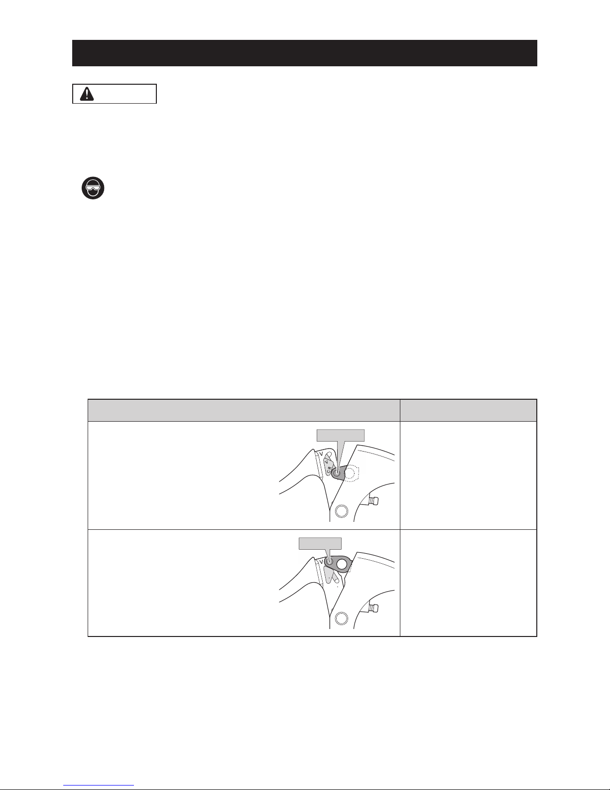
•
The brake levers are equipped with a mode switching mechanism to make them compatible with cantilever brakes and roller
brakes or V-BRAKE brakes with power modulator.
If the incorrect mode is selected it may cause either excessive or insufficient braking force to occur, which could
result in dangerous accidents.
Be sure to select the mode in accordance with the instructions given in the table below.
Mode position Applicable brake
C : Mode position for compatibility with
cantilever brakes
R : Mode position for compatibility with roller
brakes
C R
V
V
C R
C/R position
•
Cantilever brakes
•
Roller brakes
V : Mode position for compatibility with
V-BRAKE brakes with power modulator
C R
V
V
C R
V position
•
V-BRAKE brakes with power
modulator
Use the brake levers with mode switching mechanism in the combinations given above.
•
Check that the wheels are fastened securely before riding the bicycle. If the wheels are loose in any way, they may come off
the bicycle and serious injury may result.
6
For Installation to the Bicycle, and Maintenance:
•
When securing the brake arm to the frame, be sure to use a brake arm clip that matches the size of the chainstay, and securely
tighten them with the clip screw and clip nut to the specified tightening torque.
Use a lock nut with a nylon insert (self-locking nut) for the clip nut. It is recommended that standard Shimano parts be used for
the clip screw, clip nut and brake arm clip.
If the clip nut comes off the brake arm, or if the clip screw or brake arm clip becomes damaged, the brake arm may rotate on
the chainstay and cause the handlebars to jerk suddenly, or the bicycle wheel may lock and the bicycle may fall over, causing
serious injury.
•
When installing the hub to the frame, be sure to install the correct non-turn washers to the left and right sides, and securely
tighten the hub nuts to the specified torques. If the non-turn washers are installed to one side only, or if the hub nuts are not
tightened sufficiently, the non-turn washer may fall out, which could cause the hub axle to rotate and the cassette joint to
turn. This may then cause the handlebars to be accidentally pulled by the shifting cable, and an extremely serious accident
could result.
< Coaster brake hub >
•
When using a fork end with a rear-facing dropout, use the chain adjusters to remove excess slack from the chain.
CAUTION
Be sure to also inform users of the following:
•
Be sure to shift the shifting lever one gear at a time. During shifting, reduce the force being applied to the pedals. If you try to
force operation of the shifting lever or perform multi-shifting while the pedals are being turned strongly, your feet may come
off the pedals and the bicycle may topple over, which could result in serious injury.
Operating the shifting lever to multi-shift to a light gear may also cause the outer casing to spring out of the shifting lever.
This does not affect the capabilities of the shifting lever because the outer casing returns to the original position after shifting.
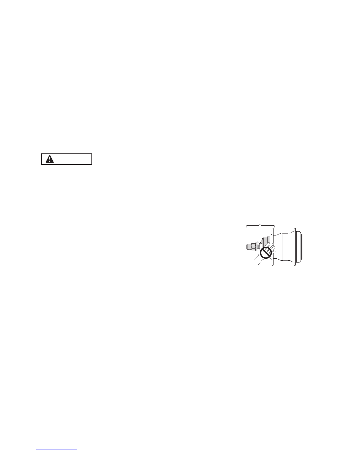
•
If the brake is used frequently, the area around the brake may become hot. Do not
touch the area around the brake for at least 30 minutes after you finish riding the
bicycle.
Area around the brake
< Coaster brake specifications >
•
Avoid continuous application of the brakes when riding down long slopes, as this will cause the internal brake parts to become
very hot, and this may weaken braking performance. It may also cause a reduction in the amount of brake grease inside the
brake, and this can lead to problems such as abnormally sudden braking.
•
Spin the wheel and confirm that the braking force of the coaster brake is correct.

7
NOTE
Be sure to also inform users of the following:
•
You can shift gears while lightly pedaling, but on rare occasions the pawls and ratchet inside the hub may produce some noise
afterwards as part of normal gear shifting operation.
•
The internal hub is not completely waterproof. Avoid using the hub in places where water might get inside it and do not use
high-pressure water to clean the hub, otherwise the internal mechanism may rust.
•
Do not disassemble the hub. If you need to disassemble it, consult the dealer where you made a purchase.
•
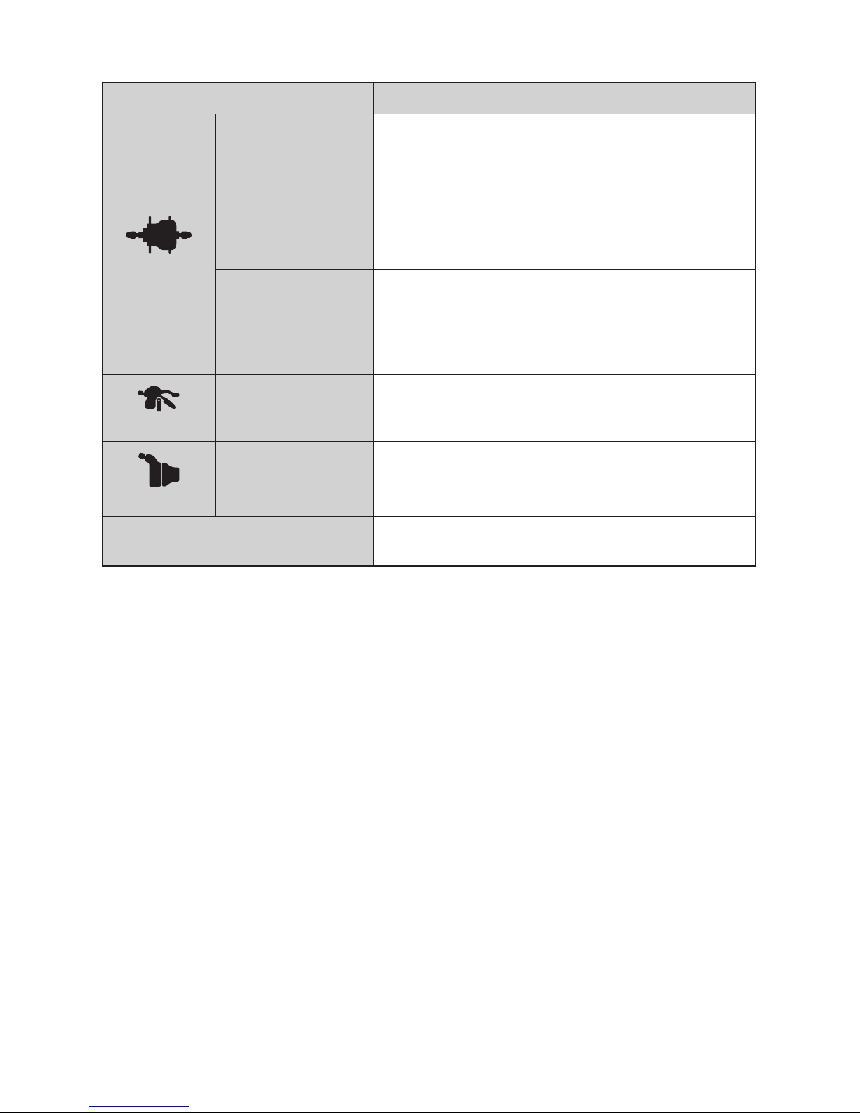
All of the following phenomena occur due to the internal gear-shifting structure and are not the failure of the internal
components.
Possible phenomena
Number of
gears for the
hub
Types of hub Gear positions
where the
phenomena might
occur
For coaster brake
For roller brakes/
V-BRAKE
If you place your foot on a pedal
and move the bicycle backwards, a
clicking will be felt in the pedal.
7-gear hub X - All gear positions
Noise occurs when the pedals are
rotating.
7-gear hub
X - All gear positions
- X 2, 3, 4, 5, 6, 7-speed
8-gear hub X -
Gear positions
except the 1st
Noise occurs when the bicycle is
pushed backward.
8-gear hub X X 5, 6, 7, 8-speed
The hub has a built-in mechanism
for facilitating gear shifting.
When the mechanism operates
during gear shifting, noise and
vibration may occur.
8-gear hub X X All gear positions
Depending on the gear position,
gear shifting may give different
feels.
7-gear hub X
X All gear positions8-gear hub X
5-gear hub -
When pedal rotation is stopped
during riding, noise will be
generated.
7-gear hub X X
All gear positions
8-gear hub X -
5-gear hub - X 4, 5-speed
•
Products are not guaranteed against natural wear and deterioration from normal use and aging.
•
For maximum performance we highly recommend Shimano lubricants and maintenance products.
< Coaster brake specifications >
•
If the wheels are not rotating smoothly, you need to replace or grease the brake shoes. Consult the dealer where you made a
purchase.

8
For Installation to the Bicycle, and Maintenance:
•
The cassette joint should only be used with sprockets from 16T to 23T.
•
It is recommended that the chain ring of the front be set to the following gear ratio.
7, 8-gear: about 2.1
5-gear: about 2.0
Example) In the case of 26 inch wheels
Front 36T 38T 46T
Rear
7, 8-gear 16T 18T 22T
5-gear 18T 19T 23T
•
In order to maintain proper performance of the product, it is recommended that you ask the place where you purchased the
bicycle or your nearest Pro shop to carry out maintenance such as greasing the internal parts about once every two years from
the first time of use (once about every 5,000 km if the bicycle is used very frequently). It is also recommended that you use the
Shimano internal hub grease or lubrication kit when carrying out maintenance. If the special grease or lubrication kit is not
used, problems such as gear shifting malfunction may occur.
•
If the wheel becomes stiff and difficult to turn, you should lubricate it with grease.
•
You should periodically wash the chainrings in a neutral detergent. In addition, cleaning the chain with neutral detergent and
lubricating it can be an effective way of extending the useful life of the chainrings and the chain.
•
If the chain keeps coming off the sprockets during use, replace the sprockets and the chain.
< Coaster brake specifications >
•
Use a wheel with 3x or 4x spoke lacing. Wheels with radial lacing cannot be used because the spokes and the wheel can be
damaged when applying the brakes and brake noise can be generated.
•
If the wheel becomes stiff and difficult to turn, you should replace the brake shoes or lubricate with grease.
•
Use only the dedicated grease for the brake shoes. When using a lubrication kit, remove the brake shoes to avoid contact with
the oil.
The actual product may differ from the illustration because this manual is intended chiefly to explain the procedures for
using the product.
9
INSTALLATION
List of tools to be used
The following tools are required to assemble the product.
Where to use Tool
Hub nut Adjustable wrench
Brake lever 5 mm Allen key
Shifting lever
RAPIDFIRE Plus 5 mm Allen key
Cover fixing screw Screwdriver (#2)
REVOSHIFT 3 mm Allen key
Cover fixing screw Screwdriver (#1)
Cassette joint Inner cable fixing bolt unit TL-CJ40 (Y70898020)
Installation of the sprocket to the hub
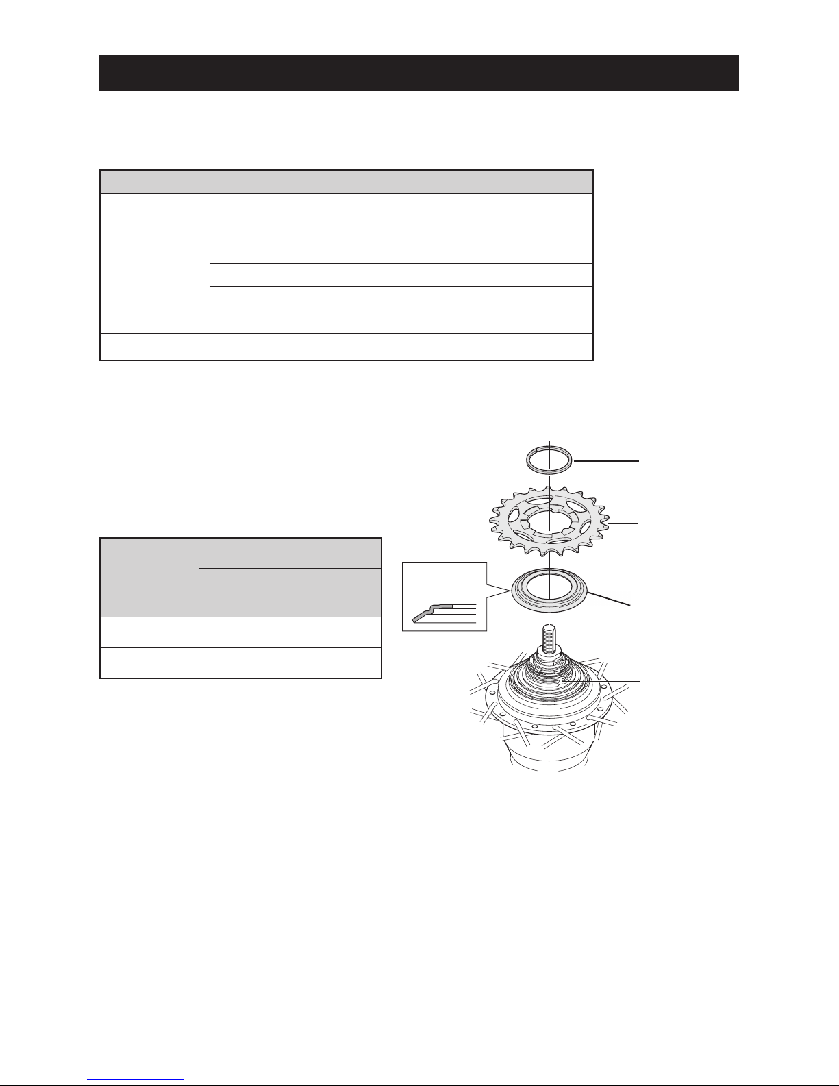
< 7-gear hub / 5-gear hub >
Place right hand dust cap onto the driver on the right side of
the hub body.
Next, install the sprocket and secure it in place with the snap
ring.
Specifications
Applicable sprockets
Outward
assembling
Inward
assembling
7-gear 16T - 23T 18T - 23T
5-gear 16T - 23T
Note the
direction
Snap ring
Sprocket
7-gear: Right hand dust cap C
5-gear: Right hand dust cap D
Driver
10
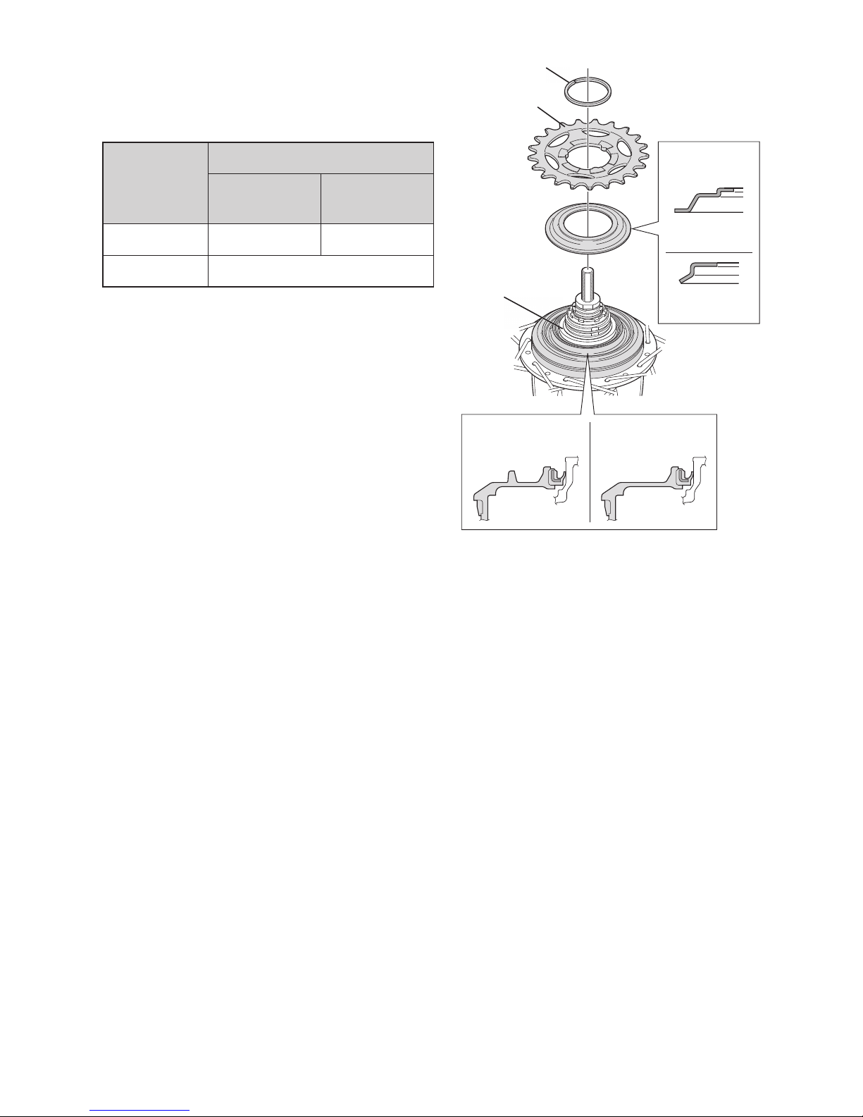
< 8-gear hub >
Place right hand dust cap C or B onto the driver on the right side
of the hub body. Next, install the sprocket and secure it in place
with the snap ring.
Specifications
Applicable sprockets
Outward
assembling
Inward
assembling
A 16T - 23T 20T - 23T
B 16T - 23T
Note:
•
For A specifications: If the sprocket is an inward assembling
sprocket with 19T or less or for belt drive specifications, right
hand dust cap A will come into contact with the chain or pulley
and so B specifications should be used instead.
•
For B specifications: If the sprocket is an inward assembling
sprocket with 16T and 3 mm teeth or for belt drive
specifications, remove right hand dust cap B before use.
Snap ring
Sprocket
Note the
direction
A specifications:
Right hand dust cap C
B specifications:
Right hand dust cap B
A specifications:
Right hand dust cap A
B specifications:
Right hand dust cap A
Driver
11
Installation of the cassette joint to the hub
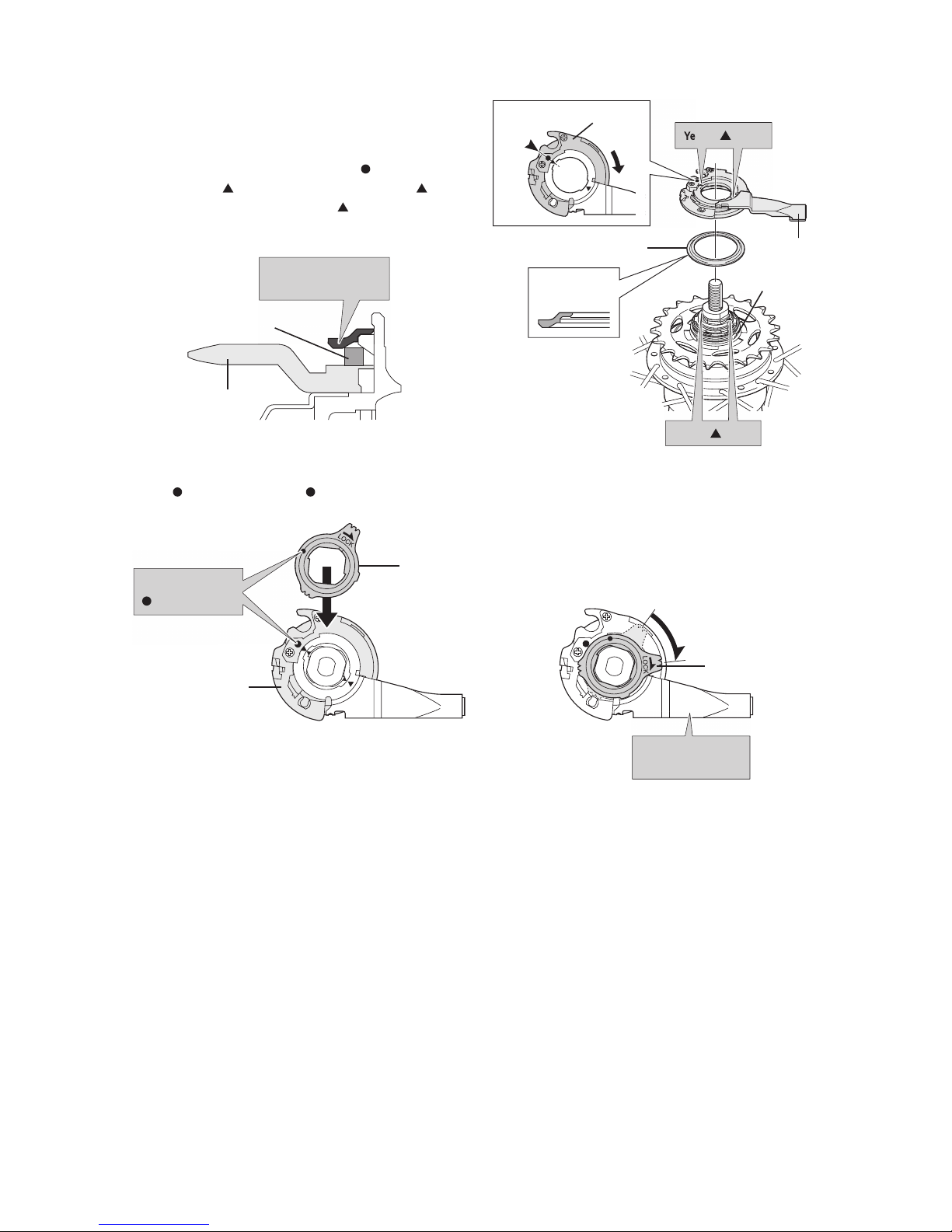
< 7-gear hub >
1.
Install the driver cap to the driver to the right side of the
hub body. Next, turn the cassette joint pulley in the
direction of the arrow so that the yellow
mark is aligned
with the yellow
mark, and then align the yellow marks
on the cassette joint with the yellow
marks on the right
side of the hub body.
Install the driver cap in
this position.
Snap ring
Sprocket
Cassette joint
Driver
Yellow marks
Yellow marks
Note the
direction
Driver cap
Yellow
Should be
aligned
Pulley
2.
Secure the cassette joint to the hub with the cassette joint fixing ring. When installing the cassette joint fixing ring, align the
yellow
mark with the yellow mark on the cassette joint pulley, and then turn the cassette joint fixing ring 45°clockwise.
Cassette joint pulley
Fit the cassette joint
bracket securely.
Cassette joint fixing
ring
Turn 45°
Align the yellow
marks to install.
Cassette joint fixing ring
12
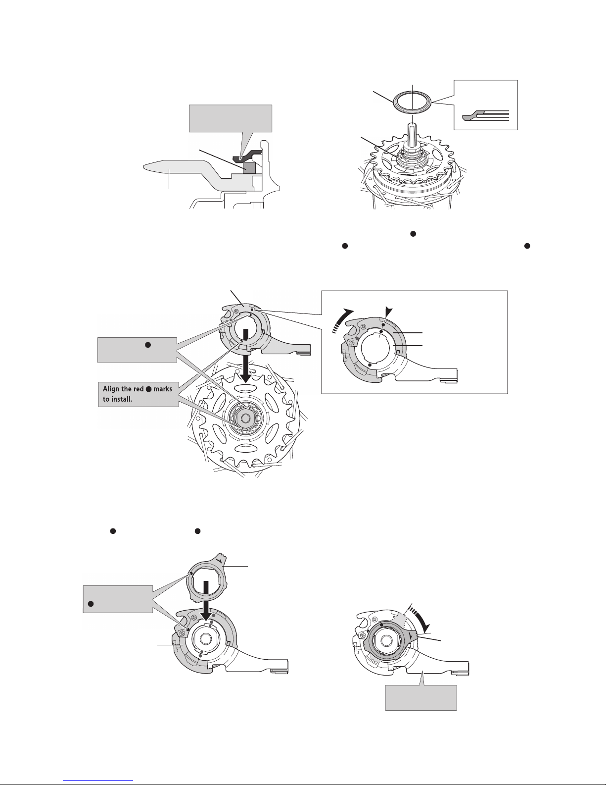
< 8-gear hub / 5-gear hub >
1.
Install the driver cap to the driver on the right side of the hub body.
Install the driver cap in
this position.
Snap ring
Sprocket
Driver cap
Driver
Note the
direction
2.
Turn the cassette joint pulley in the direction of the arrow in the illustration to align the red marks on the pulley and the
bracket. With the cassette joint in this condition, install it so that the red
mark on the cassette joint is aligned with the red
mark on the right side of the hub body.
Align the red marks
to install.
Cassette joint
Right side of the hub body
Should be aligned
Cassette joint pulley
Cassette joint bracket
Align the red
marks
to install.
Align the red marks
to install.
3.
Secure the cassette joint to the hub with the cassette joint fixing ring. When installing the cassette joint fixing ring, align the
yellow
mark with the yellow mark on the cassette joint pulley, and then turn the cassette joint fixing ring 45° clockwise.
Cassette joint fixing ring
LOCK
Align the yellow
marks to install.
Cassette joint pulley
LOCK
Fit the cassette joint
bracket securely.
Turn 45°
Cassette joint fixing
ring
 Loading...