

Page 1
t
General Safety Information
WARNING
– To avoid serious injuries:
Obtain and read the service instructions
carefully prior to installing the parts. Loose,
worn, or damaged parts may cause serious
injury to the rider.
We strongly recommend only using genuine
Shimano replacement parts.
Read these Technical Service Instructions
carefully, and keep them in a safe place for
later reference.
NOTE:
The CJ-8S40 cassette joint should only be
used with sprockets from 16T to 23T.
When lubricating the chain or the sprockets, be
careful not to get any oil on the rubber bellows
or the rubber cover of the cassette joint.
For maximum performance we highly
recommend Shimano lubricants and
maintenance products.
Parts are not guaranteed against natural wear
or deterioration resulting from normal use.
SI-74Y0A
Installation of the cassette joint
Refer to the Service Instructions for the Inter-8 hub for
details on installation of the cassette joint to the hub and
installation of the non-turn washer.
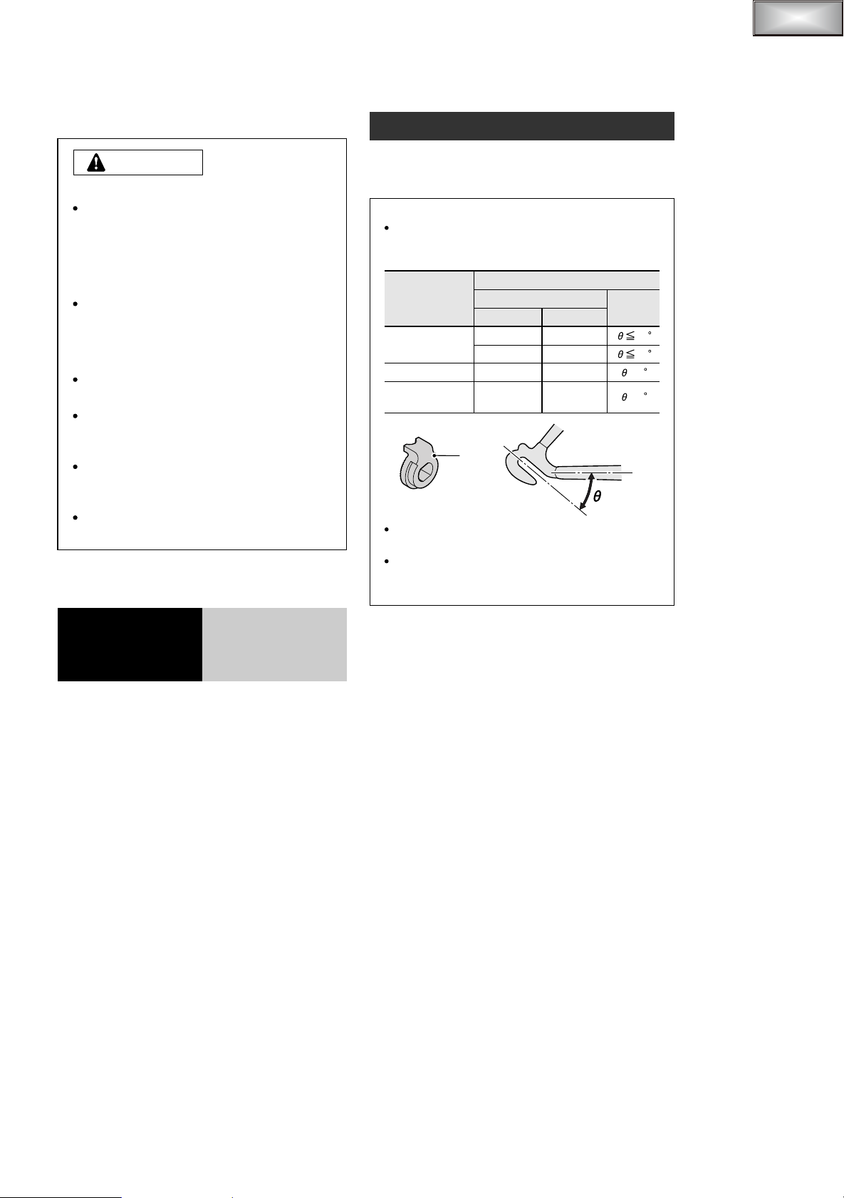
Note:
Different types of left and right non-turn washers are
available for use with standard and reversed fork
ends. Use whichever non-turn washers are suitable.
Non-turn washer
Fork end
Standard
Reversed
Reversed
(full chain case)
Mark
7R
The projecting parts should be on the fork end
side.
Install the non-turn washers so that the
projecting parts is securely in the fork end
grooves on either side of the hub axle.
Mark / Color
Right
5R / Yellow
7R / Black 7L / Gray
6R / Silver
5R / Yellow
Left
5L / Brown
6L / White
5L / Brown
Size
20
38
= 0
= 0
CJ-8S40
Cassette Joint
Technical Service Instructions
Page 2
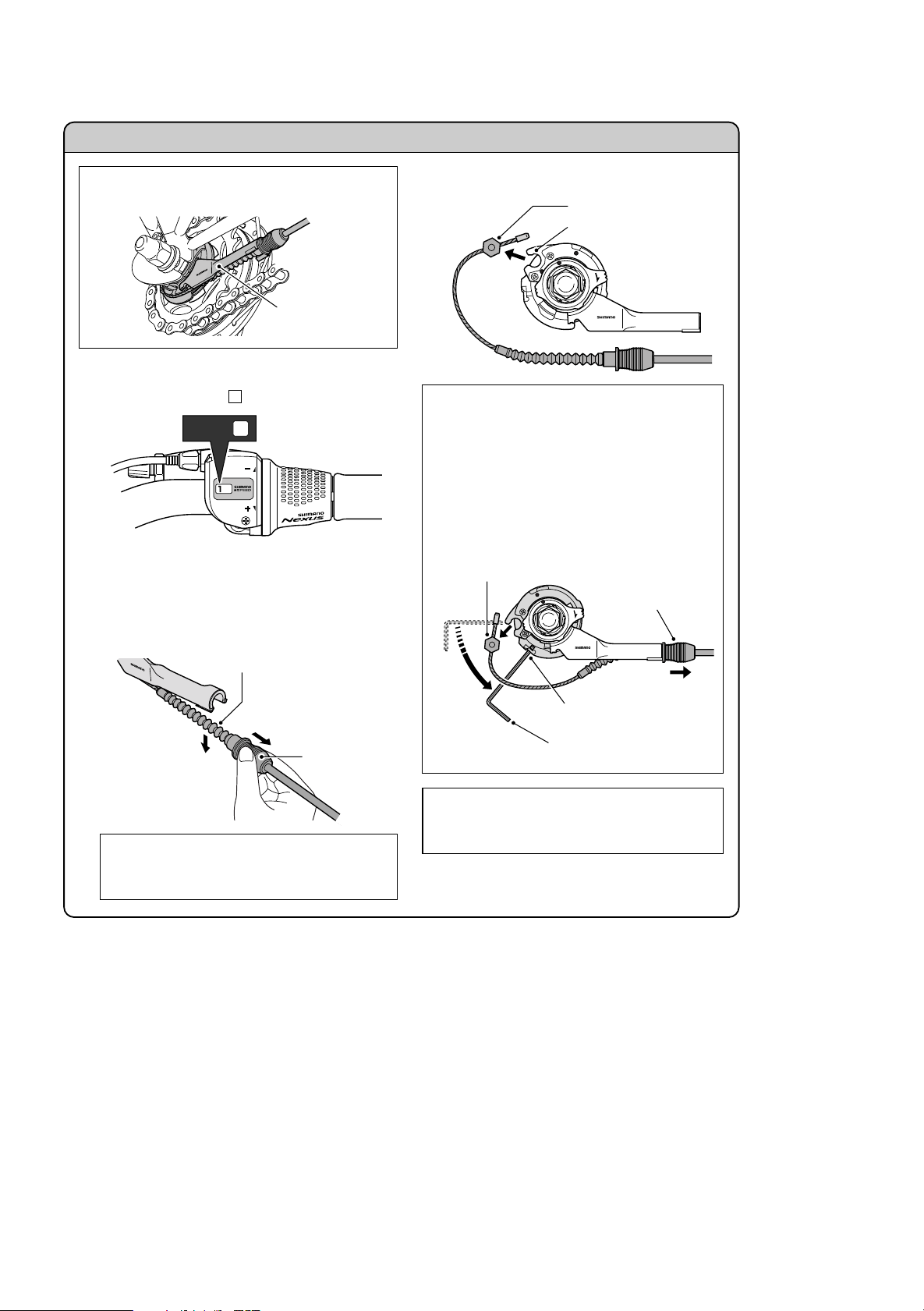
Disconnecting the shifting cable when removing the rear wheel from the frame
Remove the inner cable fixing bolt unit from the
Disconnect the cable from the cassette joint when
removing the rear wheel from the frame.
LOCK
CJ-8S40
JAPAN
3.
cassette joint pulley.
Inner cable fixing bolt unit
Cassette joint pulley
LOCK
Cassette joint
Set to
1
1
Set the shifting lever to .
1.
Hold the rubber cover and pull the outer casing holder
2.
out from the outer casing holder section of the
cassette joint. Then remove the inner cable attached
to the rubber bellows from the slit in the bracket. Be
careful not to damage the rubber bellows at this time.
CJ-8S40
JAPAN
Rubber bellows
Pull out the
outer casing
1
holder
2
Remove the
Rubber cover
rubber bellows
from the slit
Note:
Do not remove the cable by pulling the outer
casing.
CJ-8S40
JAPAN
If it is difficult to pull the outer casing holder out
from the outer casing holder section of the
cassette joint, insert a 2 mm Allen key or a #14
spoke into the hole in the cassette joint pulley,
and then turn the pulley to loosen the inner cable.
Then remove the inner cable fixing bolt unit from
the pulley first, and after this remove the outer
casing holder from the outer casing holder
section.
2
Remove the inner
cable fixing bolt unit
3
Remove the
outer casing
CJ-8S40
holder
JAPAN
LOCK
1
Turn the
pulley
Pulley hole
2 mm Allen key
or #14 spoke
Note:
If reusing the cable, refer to steps 6 to 8 in
"Installation of the shifting cable"
.
Page 3

Installation of the shifting
cable
Use a shifting cable with one inner cable drum.
SIS-SP (4 mm or 5 mm dia.)
Shifting lever end
Cassette joint end
Shield cap
Note:
Make sure that the shield cap is at the shifting lever
end.
Shifting lever side
Connect the shifting cable to the shifting lever.
1.
Refer to the Service Instructions which are
provided with the Inter-8 shifting lever.
Cassette joint side
Set the shifting lever to .
2.
1
1)
While holding the end of the rubber bellows, insert
the inner cable. Be careful not to pierce the rubber
bellows with the end of the inner cable at this time.
End of rubber bellows Inner cable
2)
Slide the rubber bellows onto the inner cable.
Rubber bellows
3)
Push the outer casing on so that it securely touches
the outer casing holder.
Inner cable
Outer casing holder
Outer casing
1
Set to
Install the rubber cover and rubber bellows to the outer
3.
casing holder.
Rubber bellows
Wipe away any grease which may be on the inner
4.
cable, and then pass the inner cable through the
rubber bellows. After this, insert the outer casing into
the rubber cover and set it into the outer casing holder.
Use a new inner cable. Do not use a cable which
has had the end cut off.
Outer casing holder
Rubber cover
Rubber bellows
After checking that the end of the outer casing is
5.
sitting securely in the cable adjustment bolt of the
shifting lever, attach the inner cable fixing bolt unit to
the inner cable.
Rubber cover
Inner cable fixing bolt unit
Note: Do not use this inner cable fixing bolt unit
with the CJ-4S30 cassette joint.
Inner cable fixing nut
Inner cable fixing washer
Inner cable fixing bolt
10 mm
(Black)
Pass the inner cable through the hole.
127 mm
Be careful of the inner cable end
OK
Not OK Not OK
63 mm or less
Pull the inner cable while attaching
the inner cable fixing bolt unit.
Tightening torque:
4 – 6 Nm {40 – 60 kgfcm}
Page 4

Bring the cable around to the cassette joint pulley,
6.
hold so that the inner cable fixing nut is facing to the
outside (toward the fork end), and then slide the flats
part of the inner cable fixing washer into the gap in the
pulley.
Flats part of inner cable
fixing washer
Outer casing holder section
CJ-8S40
JAPAN
Rubber bellows
Outer casing holder
Rubber cover
Slit
Insert the rubber
bellows into the slit
1
2
Attach the
outer casing
holder
Pulley
Gap in pulley
LOCK
CJ-8S40
JAPAN
LOCK
CJ-8S40
JAPAN
Inner cable
fixing nut
Turn the cable 60 counterclockwise and attach it to
7.
the hook.
Hook
Turn the
cable 60
If first inserting the outer casing holder into the
outer casing holder section of the cassette joint
is easier, then first insert the outer casing holder
into the outer casing holder section of the
cassette joint, and then insert a 2 mm Allen key
or a #14 spoke into the hole in the cassette joint
pulley, and then turn the pulley so that the inner
cable fixing bolt unit fits into the gap in the
pulley.
3
Insert the inner cable
fixing bolt unit
LOCK
CJ-8S40
JAPAN
1
Attach the
outer casing
holder
2
Turn the
pulley
2 mm Allen key
or #14 spoke
Hole in pulley
Attach the inner cable to the pulley as shown in the
8.
illustration, pass the part of the inner cable which has
the rubber bellows attached through the slit in the
cassette joint bracket, and then insert the outer casing
holder securely into the outer casing holder section.
Be careful not to damage the rubber bellows at this
time.
Inner cable
LOCK
CJ-8S40
JAPAN
Pulley
Bracket
Note:
Check that the inner cable is correctly seated
inside the pulley guide.
LOCK
CJ-8S40
JAPAN
Guide Guide
LOCK
OK Not OK
Secure the cable to the frame with the outer casing
9.
bands.
10 cm
10 cm
Outer casing bands
15 cm
CJ-8S40
JAPAN
Page 5

Adjusting the cassette joint
t
Set the shifting lever to .
1.
Check to be sure that the yellow setting lines on the
cassette joint bracket and pulley are aligned at this
time.
4
Yellow setting lines
After adjusting the cassette joint, cut off the excess
2.
length of inner cable and then install the inner end cap.
Inner end cap
15 – 20 mm
Set to
4
JAPAN
CJ-8S40
LOCK
The yellow setting lines on the cassette joint are
located in two places. Use the one that is easiest
to see.
When bicycle is standing up
Should be straight
Cassette joint
pulley
LOCK
CJ-8S40
Cassette joint bracket
JAPAN
When bicycle is upside down
Should be straight
JAPAN
CJ-8S40
Cassette joint
pulley
LOCK
CJ-8S40
JAPAN
These service instructions explain how to use and maintain the
Shimano bicycle parts which have been used on your new
bicycle. For any questions regarding your bicycle or other
matters which are not related to Shimano parts‚ please contact
the place of purchase or the bicycle manufacturer.
These service instructions are printed on recycled paper.
Please note: Specifications are subject to change for improvement without
notice. (English)
One Holland Irvine CA 92618 U.S. A. Phone 949 -9 51- 500 3
Industrieweg 24 NL- 807 1 CT Nunspeet‚ Holland Phone 31 -34 1-2 722 22
3- 77 Oimatsucho‚ Sakai‚ Osaka‚ Japan Phone 07 2- 223 -32 43
C
Mar. 2003 by Shimano Inc. PIT. SZK. Printed in Japan
LOCK
Cassette joint bracket
If the yellow setting lines are not aligned, turn the
cable adjustment bolt of the shifting lever to align
the setting lines. After this, move the shifting
lever once more from to and then back to
4
, and then re-check to be sure that the yellow
4 1
setting lines are aligned.
Cable adjustment bolt
 Loading...