

Page 1

GC-2014 Gas Chromatograph
INSTRUCTION MANUAL
221-40609A
Read the instruction manual thoroughly before you use the product.
Keep this instruction manual for future reference.
Page 2

©2004-2006 Shimadzu Corporation. All rights are reserved, including those to reproduce this
publication or parts there of in any form without permission in writing from Shimadzu Corporation.
Information in this publication is subject to change without notice and does not represent a
commitment on the part of the vendor.
Any errors or omissions which may have occurred in this publication despite the utmost care
taken in its production will be corrected as soon as possible, but not necessarily immediately
upon detection.
Note that Shimadzu does not have any obligation concerning the effects resulting from the application of the contents of this manual.
Page 3
About this USER’s MANUAL
About this USER’s MANUAL
GC-2014 user's manual consists of the two separate manuals as described below.
Operation Manual Part number: 221-40607
It describes procedures necessary to operate the instrument.
Instruction Manual Part number: 221-40609 (this manual)
It describes the instrument's functions and how to use them.
Safety precautions are included in the operation manual. Please read them before using the instrument.
WARNING LABELS
WARNING LABELS
Label conventions for this manual are provided below.
Indicates a potentially hazardous situation which, if not avoided,
WARNING
could result in serious injury or possibly death.
CAUTION
NOTE
Indicates a potentially hazardous situation which, if not avoided,
may result in minor to moderate injury or equipment damage.
Emphasizes additional information that is provided to ensure the
proper use of this product.
I
Page 4

This page is intentionally left blank.
Page 5

Contents
About this USER’s MANUAL
1 Installation
1.1 Verification of Installation Location . . . . . . . . . . . . . . . . . . . . . . . . . . . . . . . . . . . . . . 1
1.2 Power supply and wiring . . . . . . . . . . . . . . . . . . . . . . . . . . . . . . . . . . . . . . . . . . . . . . 4
1.3 Gas Supply Plumbing . . . . . . . . . . . . . . . . . . . . . . . . . . . . . . . . . . . . . . . . . . . . . . . . . 7
2 Before Use
2.1 Setting Analytical Flow Lines . . . . . . . . . . . . . . . . . . . . . . . . . . . . . . . . . . . . . . . . . . 17
2.2 Outputting Analog Signals to the Chromatopac . . . . . . . . . . . . . . . . . . . . . . . . . . 20
2.3 Outputting Digital Signals to a Personal Computer . . . . . . . . . . . . . . . . . . . . . . . . 23
2.4 Connecting a RS-232C Cable to the Chromatopac C-R8A . . . . . . . . . . . . . . . . . . 25
2.5 Connecting Auto Injector/Auto Sampler AOC-20 Series . . . . . . . . . . . . . . . . . . . . 27
2.6 Connecting the Relay Terminals . . . . . . . . . . . . . . . . . . . . . . . . . . . . . . . . . . . . . . . 29
3 Installing Packed Columns and Setting Analytical Flow Lines
3.1 Installation Location for Packed Columns . . . . . . . . . . . . . . . . . . . . . . . . . . . . . . . 31
3.2 Dual-Column Packed FID Analysis . . . . . . . . . . . . . . . . . . . . . . . . . . . . . . . . . . . . . 33
3.3 Single-Column Packed FID Analysis . . . . . . . . . . . . . . . . . . . . . . . . . . . . . . . . . . . . 36
3.4 Packed TCD Analysis . . . . . . . . . . . . . . . . . . . . . . . . . . . . . . . . . . . . . . . . . . . . . . . . 39
3.5 Packed Analysis Using the Single DET . . . . . . . . . . . . . . . . . . . . . . . . . . . . . . . . . . 42
4 Installing Capillary Columns and Setting Analytical Flow Lines
4.1 Installation Location for Capillary Columns . . . . . . . . . . . . . . . . . . . . . . . . . . . . . . 47
4.2 Capillary Analysis Using the Dual FID
(When a detector adapter with purge is used) . . . . . . . . . . . . . . . . . . . . . . . . . . . . 49
4.3 Capillary Analysis Using the Dual FID
(When a makeup gas flow controller is used) . . . . . . . . . . . . . . . . . . . . . . . . . . . . 52
4.4 Capillary TCD Analysis . . . . . . . . . . . . . . . . . . . . . . . . . . . . . . . . . . . . . . . . . . . . . . . 54
4.5 Single DET . . . . . . . . . . . . . . . . . . . . . . . . . . . . . . . . . . . . . . . . . . . . . . . . . . . . . . . . .58
5 Analysis
5.1 Analysis Flow Chart . . . . . . . . . . . . . . . . . . . . . . . . . . . . . . . . . . . . . . . . . . . . . . . . . 61
5.1.1 Preparation . . . . . . . . . . . . . . . . . . . . . . . . . . . . . . . . . . . . . . . . . . . . . . . . . . . . . . . . . . . . . . . . . . 61
5.1.2 Setting Parameters . . . . . . . . . . . . . . . . . . . . . . . . . . . . . . . . . . . . . . . . . . . . . . . . . . . . . . . . . . . . 61
5.1.3 Analysis . . . . . . . . . . . . . . . . . . . . . . . . . . . . . . . . . . . . . . . . . . . . . . . . . . . . . . . . . . . . . . . . . . . . 62
GC-2014
i
Page 6

Contents
5.2 Notes for Analysis . . . . . . . . . . . . . . . . . . . . . . . . . . . . . . . . . . . . . . . . . . . . . . . . . . . 63
6 Basic Key Operation
6.1 Keypad Description and Operation . . . . . . . . . . . . . . . . . . . . . . . . . . . . . . . . . . . . . 67
6.1.1 Keypad operation . . . . . . . . . . . . . . . . . . . . . . . . . . . . . . . . . . . . . . . . . . . . . . . . . . . . . . . . . . . . . 68
6.1.2 Screen . . . . . . . . . . . . . . . . . . . . . . . . . . . . . . . . . . . . . . . . . . . . . . . . . . . . . . . . . . . . . . . . . . . . . 69
6.1.3 Status indicators . . . . . . . . . . . . . . . . . . . . . . . . . . . . . . . . . . . . . . . . . . . . . . . . . . . . . . . . . . . . . . 70
6.2 Adjusting The Display . . . . . . . . . . . . . . . . . . . . . . . . . . . . . . . . . . . . . . . . . . . . . . . . 71
6.3 Basic Key Operations . . . . . . . . . . . . . . . . . . . . . . . . . . . . . . . . . . . . . . . . . . . . . . . . 72
6.3.1 Screen display . . . . . . . . . . . . . . . . . . . . . . . . . . . . . . . . . . . . . . . . . . . . . . . . . . . . . . . . . . . . . . . 72
6.3.2 Moving the cursor . . . . . . . . . . . . . . . . . . . . . . . . . . . . . . . . . . . . . . . . . . . . . . . . . . . . . . . . . . . . . 73
6.3.3 Entering numeric values . . . . . . . . . . . . . . . . . . . . . . . . . . . . . . . . . . . . . . . . . . . . . . . . . . . . . . . . 74
6.3.4 Changing a selection . . . . . . . . . . . . . . . . . . . . . . . . . . . . . . . . . . . . . . . . . . . . . . . . . . . . . . . . . . 74
6.3.5 Changing item names . . . . . . . . . . . . . . . . . . . . . . . . . . . . . . . . . . . . . . . . . . . . . . . . . . . . . . . . . . 75
6.4 Getting Help . . . . . . . . . . . . . . . . . . . . . . . . . . . . . . . . . . . . . . . . . . . . . . . . . . . . . . . . 77
6.4.1 Screen description . . . . . . . . . . . . . . . . . . . . . . . . . . . . . . . . . . . . . . . . . . . . . . . . . . . . . . . . . . . . 77
6.4.2 PF menu . . . . . . . . . . . . . . . . . . . . . . . . . . . . . . . . . . . . . . . . . . . . . . . . . . . . . . . . . . . . . . . . . . . . 77
7 Starting and Stopping the GC [SYSTEM]
7.1 [SYSTEM] Key Main Screen . . . . . . . . . . . . . . . . . . . . . . . . . . . . . . . . . . . . . . . . . . . 79
7.1.1 Screen Description . . . . . . . . . . . . . . . . . . . . . . . . . . . . . . . . . . . . . . . . . . . . . . . . . . . . . . . . . . . . 79
7.1.2 Parameter . . . . . . . . . . . . . . . . . . . . . . . . . . . . . . . . . . . . . . . . . . . . . . . . . . . . . . . . . . . . . . . . . . . 80
7.1.3 PF menu . . . . . . . . . . . . . . . . . . . . . . . . . . . . . . . . . . . . . . . . . . . . . . . . . . . . . . . . . . . . . . . . . . . . 81
7.2 Specifying Clean Up Parameters . . . . . . . . . . . . . . . . . . . . . . . . . . . . . . . . . . . . . . . 82
7.2.1 Screen Description . . . . . . . . . . . . . . . . . . . . . . . . . . . . . . . . . . . . . . . . . . . . . . . . . . . . . . . . . . . 82
7.2.2 Parameter list . . . . . . . . . . . . . . . . . . . . . . . . . . . . . . . . . . . . . . . . . . . . . . . . . . . . . . . . . . . . . . . . 83
7.2.3 PF menu . . . . . . . . . . . . . . . . . . . . . . . . . . . . . . . . . . . . . . . . . . . . . . . . . . . . . . . . . . . . . . . . . . . . 85
7.3 Specifying Start Procedures . . . . . . . . . . . . . . . . . . . . . . . . . . . . . . . . . . . . . . . . . . 86
7.3.1 Screen description . . . . . . . . . . . . . . . . . . . . . . . . . . . . . . . . . . . . . . . . . . . . . . . . . . . . . . . . . . . . 86
7.3.2 Parameter list . . . . . . . . . . . . . . . . . . . . . . . . . . . . . . . . . . . . . . . . . . . . . . . . . . . . . . . . . . . . . . . . 87
7.3.3 Example: starting the system with carrier gas flow . . . . . . . . . . . . . . . . . . . . . . . . . . . . . . . . . . . . 87
7.4 Specifying the Stop Procedures . . . . . . . . . . . . . . . . . . . . . . . . . . . . . . . . . . . . . . . 88
7.4.1 Screen . . . . . . . . . . . . . . . . . . . . . . . . . . . . . . . . . . . . . . . . . . . . . . . . . . . . . . . . . . . . . . . . . . . . . 88
7.4.2 Parameter list . . . . . . . . . . . . . . . . . . . . . . . . . . . . . . . . . . . . . . . . . . . . . . . . . . . . . . . . . . . . . . . . 88
7.4.3 System shut down examples . . . . . . . . . . . . . . . . . . . . . . . . . . . . . . . . . . . . . . . . . . . . . . . . . . . . 89
8 Setting the Analytical Parameters and File Management
8.1 [SET] Key Main Screen . . . . . . . . . . . . . . . . . . . . . . . . . . . . . . . . . . . . . . . . . . . . . . . 91
8.1.1 Main screen . . . . . . . . . . . . . . . . . . . . . . . . . . . . . . . . . . . . . . . . . . . . . . . . . . . . . . . . . . . . . . . . . 91
8.1.2 Parameter list . . . . . . . . . . . . . . . . . . . . . . . . . . . . . . . . . . . . . . . . . . . . . . . . . . . . . . . . . . . . . . . . 92
8.1.3 PF menu . . . . . . . . . . . . . . . . . . . . . . . . . . . . . . . . . . . . . . . . . . . . . . . . . . . . . . . . . . . . . . . . . . . . 94
8.2 File Management . . . . . . . . . . . . . . . . . . . . . . . . . . . . . . . . . . . . . . . . . . . . . . . . . . . . 95
8.2.1 Screen description . . . . . . . . . . . . . . . . . . . . . . . . . . . . . . . . . . . . . . . . . . . . . . . . . . . . . . . . . . . . 95
8.2.2 PF menu . . . . . . . . . . . . . . . . . . . . . . . . . . . . . . . . . . . . . . . . . . . . . . . . . . . . . . . . . . . . . . . . . . . . 95
8.2.3 Copying a file . . . . . . . . . . . . . . . . . . . . . . . . . . . . . . . . . . . . . . . . . . . . . . . . . . . . . . . . . . . . . . . . 96
8.2.4 Renaming a file . . . . . . . . . . . . . . . . . . . . . . . . . . . . . . . . . . . . . . . . . . . . . . . . . . . . . . . . . . . . . . . 96
8.2.5 Initializing a file . . . . . . . . . . . . . . . . . . . . . . . . . . . . . . . . . . . . . . . . . . . . . . . . . . . . . . . . . . . . . . . 97
ii
GC-2014
Page 7

Contents
8.3 Specifying the Analytical Flow Line Components ([Line Config]) . . . . . . . . . . . . 98
8.3.1 Screen description . . . . . . . . . . . . . . . . . . . . . . . . . . . . . . . . . . . . . . . . . . . . . . . . . . . . . . . . . . . . 98
8.4 Changing Items Displayed with [Customiz] . . . . . . . . . . . . . . . . . . . . . . . . . . . . . 101
8.4.1 Screen description . . . . . . . . . . . . . . . . . . . . . . . . . . . . . . . . . . . . . . . . . . . . . . . . . . . . . . . . . . . 101
9 Monitoring the GC
9.1 [MONIT] key Main Screen . . . . . . . . . . . . . . . . . . . . . . . . . . . . . . . . . . . . . . . . . . . . 103
9.1.1 Screen description . . . . . . . . . . . . . . . . . . . . . . . . . . . . . . . . . . . . . . . . . . . . . . . . . . . . . . . . . . . 103
9.1.2 Parameter list . . . . . . . . . . . . . . . . . . . . . . . . . . . . . . . . . . . . . . . . . . . . . . . . . . . . . . . . . . . . . . . 105
9.1.3 PF menu . . . . . . . . . . . . . . . . . . . . . . . . . . . . . . . . . . . . . . . . . . . . . . . . . . . . . . . . . . . . . . . . . . . 105
9.2 Monitoring the Temperature with [Temp Mon] . . . . . . . . . . . . . . . . . . . . . . . . . . . 106
9.2.1 Screen description . . . . . . . . . . . . . . . . . . . . . . . . . . . . . . . . . . . . . . . . . . . . . . . . . . . . . . . . . . . 106
9.2.2 PF menu . . . . . . . . . . . . . . . . . . . . . . . . . . . . . . . . . . . . . . . . . . . . . . . . . . . . . . . . . . . . . . . . . . . 106
9.3 Monitoring the Flow Rate with [Flow Mon] . . . . . . . . . . . . . . . . . . . . . . . . . . . . . . 107
9.3.1 Screen description . . . . . . . . . . . . . . . . . . . . . . . . . . . . . . . . . . . . . . . . . . . . . . . . . . . . . . . . . . . 107
9.3.2 PF menu . . . . . . . . . . . . . . . . . . . . . . . . . . . . . . . . . . . . . . . . . . . . . . . . . . . . . . . . . . . . . . . . . . . 107
9.4 Zero Point Adjustment . . . . . . . . . . . . . . . . . . . . . . . . . . . . . . . . . . . . . . . . . . . . . . 108
9.4.1 Screen description . . . . . . . . . . . . . . . . . . . . . . . . . . . . . . . . . . . . . . . . . . . . . . . . . . . . . . . . . . . 108
10 Starting and Stopping Analysis
10.1 Making an Injecting and Starting an Analysis . . . . . . . . . . . . . . . . . . . . . . . . . . . 109
10.1.1 Verifying the gas chromatograph status . . . . . . . . . . . . . . . . . . . . . . . . . . . . . . . . . . . . . . . . . . . 109
10.1.2 Making manual injection . . . . . . . . . . . . . . . . . . . . . . . . . . . . . . . . . . . . . . . . . . . . . . . . . . . . . . . 110
10.1.3 Starting the analysis . . . . . . . . . . . . . . . . . . . . . . . . . . . . . . . . . . . . . . . . . . . . . . . . . . . . . . . . . . 111
10.2 Terminating the Analysis . . . . . . . . . . . . . . . . . . . . . . . . . . . . . . . . . . . . . . . . . . . . 112
10.2.1 Terminating the analysis . . . . . . . . . . . . . . . . . . . . . . . . . . . . . . . . . . . . . . . . . . . . . . . . . . . . . . . 112
10.2.2 External devices . . . . . . . . . . . . . . . . . . . . . . . . . . . . . . . . . . . . . . . . . . . . . . . . . . . . . . . . . . . . . 112
11 Creating an Oven Temperature Program
11.1 [COL] Key Main Screen . . . . . . . . . . . . . . . . . . . . . . . . . . . . . . . . . . . . . . . . . . . . . . 113
11.1.1 Screen description . . . . . . . . . . . . . . . . . . . . . . . . . . . . . . . . . . . . . . . . . . . . . . . . . . . . . . . . . . . 113
11.1.2 Parameter list . . . . . . . . . . . . . . . . . . . . . . . . . . . . . . . . . . . . . . . . . . . . . . . . . . . . . . . . . . . . . . .114
11.1.3 PF menu . . . . . . . . . . . . . . . . . . . . . . . . . . . . . . . . . . . . . . . . . . . . . . . . . . . . . . . . . . . . . . . . . . . 114
11.2 Temperature Programs . . . . . . . . . . . . . . . . . . . . . . . . . . . . . . . . . . . . . . . . . . . . . . 115
11.2.1 Isothermal analysis . . . . . . . . . . . . . . . . . . . . . . . . . . . . . . . . . . . . . . . . . . . . . . . . . . . . . . . . . . . 115
11.2.2 Programmed analysis . . . . . . . . . . . . . . . . . . . . . . . . . . . . . . . . . . . . . . . . . . . . . . . . . . . . . . . . . 115
11.2.3 Creating a temperature program . . . . . . . . . . . . . . . . . . . . . . . . . . . . . . . . . . . . . . . . . . . . . . . . 115
12 Injection Port
12.1 Packed Column Injection Port (Dual INJ) . . . . . . . . . . . . . . . . . . . . . . . . . . . . . . . 119
12.1.1 Setting the temperature with [INJ] key . . . . . . . . . . . . . . . . . . . . . . . . . . . . . . . . . . . . . . . . . . . . 120
12.1.2 Setting the Flow Rate . . . . . . . . . . . . . . . . . . . . . . . . . . . . . . . . . . . . . . . . . . . . . . . . . . . . . . . . . 122
12.1.3 Entering Columns Parameters . . . . . . . . . . . . . . . . . . . . . . . . . . . . . . . . . . . . . . . . . . . . . . . . . .124
12.1.4 Creating a Flow Rate Program . . . . . . . . . . . . . . . . . . . . . . . . . . . . . . . . . . . . . . . . . . . . . . . . . . 125
12.2 Split/Splitless Injection System . . . . . . . . . . . . . . . . . . . . . . . . . . . . . . . . . . . . . . . 126
GC-2014
iii
Page 8

Contents
12.2.1 Setting the temperature with [INJ] key . . . . . . . . . . . . . . . . . . . . . . . . . . . . . . . . . . . . . . . . . . . . 127
12.2.2 Setting the flow rate with [FLOW] key . . . . . . . . . . . . . . . . . . . . . . . . . . . . . . . . . . . . . . . . . . . .129
12.2.3 Setting column parameters . . . . . . . . . . . . . . . . . . . . . . . . . . . . . . . . . . . . . . . . . . . . . . . . . . . . . 133
12.2.4 Gas saver . . . . . . . . . . . . . . . . . . . . . . . . . . . . . . . . . . . . . . . . . . . . . . . . . . . . . . . . . . . . . . . . . . 134
12.2.5 Pressure program . . . . . . . . . . . . . . . . . . . . . . . . . . . . . . . . . . . . . . . . . . . . . . . . . . . . . . . . . . . . 135
12.2.6 Creating a Flow rate program . . . . . . . . . . . . . . . . . . . . . . . . . . . . . . . . . . . . . . . . . . . . . . . . . . . 137
12.2.7 Split ratio program . . . . . . . . . . . . . . . . . . . . . . . . . . . . . . . . . . . . . . . . . . . . . . . . . . . . . . . . . . . 139
12.2.8 Septum purge . . . . . . . . . . . . . . . . . . . . . . . . . . . . . . . . . . . . . . . . . . . . . . . . . . . . . . . . . . . . . . . 141
12.2.9 High pressure injection and splitter fix mode . . . . . . . . . . . . . . . . . . . . . . . . . . . . . . . . . . . . . . . 143
12.3 Direct Injection System . . . . . . . . . . . . . . . . . . . . . . . . . . . . . . . . . . . . . . . . . . . . . . 145
12.3.1 Setting the temperature . . . . . . . . . . . . . . . . . . . . . . . . . . . . . . . . . . . . . . . . . . . . . . . . . . . . . . . 146
12.3.2 Setting the flow rate . . . . . . . . . . . . . . . . . . . . . . . . . . . . . . . . . . . . . . . . . . . . . . . . . . . . . . . . . . 147
12.4 AFC and APC Offset Calibration . . . . . . . . . . . . . . . . . . . . . . . . . . . . . . . . . . . . . . 149
12.5 Setting the Flow Rate Parameters . . . . . . . . . . . . . . . . . . . . . . . . . . . . . . . . . . . . . 150
13 Detector
13.1 Hydrogen Flame Ionization Detector (FID) . . . . . . . . . . . . . . . . . . . . . . . . . . . . . . 153
13.1.1 Principle of FID operation . . . . . . . . . . . . . . . . . . . . . . . . . . . . . . . . . . . . . . . . . . . . . . . . . . . . . . 153
13.1.2 Setting the detector . . . . . . . . . . . . . . . . . . . . . . . . . . . . . . . . . . . . . . . . . . . . . . . . . . . . . . . . . .154
13.1.3 Setting the Detector Gas (manual flow controller) . . . . . . . . . . . . . . . . . . . . . . . . . . . . . . . . . . . 157
13.1.4 Setting the detector gas flows(APC) . . . . . . . . . . . . . . . . . . . . . . . . . . . . . . . . . . . . . . . . . . . . . . 159
13.1.5 Igniting and Extinguishing the FID . . . . . . . . . . . . . . . . . . . . . . . . . . . . . . . . . . . . . . . . . . . . . . . 161
13.2 Thermal Conductivity Detector (TCD) . . . . . . . . . . . . . . . . . . . . . . . . . . . . . . . . . . 164
13.2.1 Principle of TCD operation . . . . . . . . . . . . . . . . . . . . . . . . . . . . . . . . . . . . . . . . . . . . . . . . . . . . .164
13.2.2 Setting the detector . . . . . . . . . . . . . . . . . . . . . . . . . . . . . . . . . . . . . . . . . . . . . . . . . . . . . . . . . .165
13.2.3 TCD Zero Point Adjustment . . . . . . . . . . . . . . . . . . . . . . . . . . . . . . . . . . . . . . . . . . . . . . . . . . . . 169
13.3 Filter Signal Time Constant . . . . . . . . . . . . . . . . . . . . . . . . . . . . . . . . . . . . . . . . . . 170
13.4 Background Compensation . . . . . . . . . . . . . . . . . . . . . . . . . . . . . . . . . . . . . . . . . . 171
14 Diagnosis
14.1 Standard Diagnosis . . . . . . . . . . . . . . . . . . . . . . . . . . . . . . . . . . . . . . . . . . . . . . . . . 173
14.1.1 Screen description . . . . . . . . . . . . . . . . . . . . . . . . . . . . . . . . . . . . . . . . . . . . . . . . . . . . . . . . . . . 173
14.1.2 PF menu . . . . . . . . . . . . . . . . . . . . . . . . . . . . . . . . . . . . . . . . . . . . . . . . . . . . . . . . . . . . . . . . . . . 173
14.1.3 Diagnosis Parameters . . . . . . . . . . . . . . . . . . . . . . . . . . . . . . . . . . . . . . . . . . . . . . . . . . . . . . . . 174
14.1.4 Diagnosis parameter list . . . . . . . . . . . . . . . . . . . . . . . . . . . . . . . . . . . . . . . . . . . . . . . . . . . . . . . 175
14.1.5 Starting the diagnosis . . . . . . . . . . . . . . . . . . . . . . . . . . . . . . . . . . . . . . . . . . . . . . . . . . . . . . . . 177
14.1.6 PF menu . . . . . . . . . . . . . . . . . . . . . . . . . . . . . . . . . . . . . . . . . . . . . . . . . . . . . . . . . . . . . . . . . . . 177
14.1.7 Stopping/exiting the diagnosis . . . . . . . . . . . . . . . . . . . . . . . . . . . . . . . . . . . . . . . . . . . . . . . . . . 178
14.1.8 PF menu . . . . . . . . . . . . . . . . . . . . . . . . . . . . . . . . . . . . . . . . . . . . . . . . . . . . . . . . . . . . . . . . . . . 178
14.1.9 Diagnosis results . . . . . . . . . . . . . . . . . . . . . . . . . . . . . . . . . . . . . . . . . . . . . . . . . . . . . . . . . . . . 179
14.1.10 PF menu . . . . . . . . . . . . . . . . . . . . . . . . . . . . . . . . . . . . . . . . . . . . . . . . . . . . . . . . . . . . . . . . . . . 179
14.2 Log Reading Menu . . . . . . . . . . . . . . . . . . . . . . . . . . . . . . . . . . . . . . . . . . . . . . . . . 181
14.2.1 Screen description . . . . . . . . . . . . . . . . . . . . . . . . . . . . . . . . . . . . . . . . . . . . . . . . . . . . . . . . . . . 181
14.2.2 Parameter list . . . . . . . . . . . . . . . . . . . . . . . . . . . . . . . . . . . . . . . . . . . . . . . . . . . . . . . . . . . . . . .181
14.2.3 GC Operation log . . . . . . . . . . . . . . . . . . . . . . . . . . . . . . . . . . . . . . . . . . . . . . . . . . . . . . . . . . . . 182
14.2.4 Analysis log . . . . . . . . . . . . . . . . . . . . . . . . . . . . . . . . . . . . . . . . . . . . . . . . . . . . . . . . . . . . . . . .183
14.2.5 Parameter log . . . . . . . . . . . . . . . . . . . . . . . . . . . . . . . . . . . . . . . . . . . . . . . . . . . . . . . . . . . . . . . 185
14.2.6 Error log . . . . . . . . . . . . . . . . . . . . . . . . . . . . . . . . . . . . . . . . . . . . . . . . . . . . . . . . . . . . . . . . . . . 186
14.2.7 Diagnostic log . . . . . . . . . . . . . . . . . . . . . . . . . . . . . . . . . . . . . . . . . . . . . . . . . . . . . . . . . . . . . . . 187
14.3 Analysis Counter . . . . . . . . . . . . . . . . . . . . . . . . . . . . . . . . . . . . . . . . . . . . . . . . . . . 188
iv
GC-2014
Page 9

Contents
14.3.1 Screen description . . . . . . . . . . . . . . . . . . . . . . . . . . . . . . . . . . . . . . . . . . . . . . . . . . . . . . . . . . . 188
14.3.2 Parameter list . . . . . . . . . . . . . . . . . . . . . . . . . . . . . . . . . . . . . . . . . . . . . . . . . . . . . . . . . . . . . . .189
14.3.3 PF menu . . . . . . . . . . . . . . . . . . . . . . . . . . . . . . . . . . . . . . . . . . . . . . . . . . . . . . . . . . . . . . . . . . . 189
14.4 Coolant Consumption Counter . . . . . . . . . . . . . . . . . . . . . . . . . . . . . . . . . . . . . . . 190
14.4.1 Screen description . . . . . . . . . . . . . . . . . . . . . . . . . . . . . . . . . . . . . . . . . . . . . . . . . . . . . . . . . . . 190
14.4.2 Parameter list . . . . . . . . . . . . . . . . . . . . . . . . . . . . . . . . . . . . . . . . . . . . . . . . . . . . . . . . . . . . . . .191
14.4.3 PF menu . . . . . . . . . . . . . . . . . . . . . . . . . . . . . . . . . . . . . . . . . . . . . . . . . . . . . . . . . . . . . . . . . . . 191
14.5 Standard Installation Test . . . . . . . . . . . . . . . . . . . . . . . . . . . . . . . . . . . . . . . . . . . . 192
14.5.1 Screen description . . . . . . . . . . . . . . . . . . . . . . . . . . . . . . . . . . . . . . . . . . . . . . . . . . . . . . . . . . . 192
14.5.2 PF menu . . . . . . . . . . . . . . . . . . . . . . . . . . . . . . . . . . . . . . . . . . . . . . . . . . . . . . . . . . . . . . . . . . 192
14.5.3 Test procedure . . . . . . . . . . . . . . . . . . . . . . . . . . . . . . . . . . . . . . . . . . . . . . . . . . . . . . . . . . . . . .193
14.6 Peak Generator . . . . . . . . . . . . . . . . . . . . . . . . . . . . . . . . . . . . . . . . . . . . . . . . . . . . 194
14.6.1 Screen description . . . . . . . . . . . . . . . . . . . . . . . . . . . . . . . . . . . . . . . . . . . . . . . . . . . . . . . . . . . 194
14.6.2 Parameter list . . . . . . . . . . . . . . . . . . . . . . . . . . . . . . . . . . . . . . . . . . . . . . . . . . . . . . . . . . . . . . .194
14.6.3 PF menu . . . . . . . . . . . . . . . . . . . . . . . . . . . . . . . . . . . . . . . . . . . . . . . . . . . . . . . . . . . . . . . . . . 194
15 Optional Devices
15.1 Auto Injector Parameters . . . . . . . . . . . . . . . . . . . . . . . . . . . . . . . . . . . . . . . . . . . . 195
15.1.1 Screen description . . . . . . . . . . . . . . . . . . . . . . . . . . . . . . . . . . . . . . . . . . . . . . . . . . . . . . . . . . . 195
15.1.2 Parameter list . . . . . . . . . . . . . . . . . . . . . . . . . . . . . . . . . . . . . . . . . . . . . . . . . . . . . . . . . . . . . . .196
15.1.3 PF menu . . . . . . . . . . . . . . . . . . . . . . . . . . . . . . . . . . . . . . . . . . . . . . . . . . . . . . . . . . . . . . . . . . . 197
15.1.4 AOC priority analysis . . . . . . . . . . . . . . . . . . . . . . . . . . . . . . . . . . . . . . . . . . . . . . . . . . . . . . . . . 198
15.1.5 Parameter list . . . . . . . . . . . . . . . . . . . . . . . . . . . . . . . . . . . . . . . . . . . . . . . . . . . . . . . . . . . . . . .198
15.1.6 PF menu . . . . . . . . . . . . . . . . . . . . . . . . . . . . . . . . . . . . . . . . . . . . . . . . . . . . . . . . . . . . . . . . . . . 199
15.1.7 Other AOC parameters . . . . . . . . . . . . . . . . . . . . . . . . . . . . . . . . . . . . . . . . . . . . . . . . . . . . . . . . 199
15.1.8 Other AOC Parameter . . . . . . . . . . . . . . . . . . . . . . . . . . . . . . . . . . . . . . . . . . . . . . . . . . . . . . . . 200
15.1.9 PF menu . . . . . . . . . . . . . . . . . . . . . . . . . . . . . . . . . . . . . . . . . . . . . . . . . . . . . . . . . . . . . . . . . . . 201
15.1.10 Auto-sampler carousel and other optional parameters . . . . . . . . . . . . . . . . . . . . . . . . . . . . . . . . 202
15.1.11 Parameter list . . . . . . . . . . . . . . . . . . . . . . . . . . . . . . . . . . . . . . . . . . . . . . . . . . . . . . . . . . . . . . . 202
15.2 Setting AUX Temperature . . . . . . . . . . . . . . . . . . . . . . . . . . . . . . . . . . . . . . . . . . . . 203
15.2.1 Screen description . . . . . . . . . . . . . . . . . . . . . . . . . . . . . . . . . . . . . . . . . . . . . . . . . . . . . . . . . . . 203
15.2.2 Parameter list . . . . . . . . . . . . . . . . . . . . . . . . . . . . . . . . . . . . . . . . . . . . . . . . . . . . . . . . . . . . . . .203
15.2.3 PF menu . . . . . . . . . . . . . . . . . . . . . . . . . . . . . . . . . . . . . . . . . . . . . . . . . . . . . . . . . . . . . . . . . . . 203
15.2.4 On/Off setting . . . . . . . . . . . . . . . . . . . . . . . . . . . . . . . . . . . . . . . . . . . . . . . . . . . . . . . . . . . . . . .204
15.2.5 On/Off parameter list . . . . . . . . . . . . . . . . . . . . . . . . . . . . . . . . . . . . . . . . . . . . . . . . . . . . . . . . . 204
15.3 Setting the AUX APC Parameters . . . . . . . . . . . . . . . . . . . . . . . . . . . . . . . . . . . . . 205
15.3.1 Screen description . . . . . . . . . . . . . . . . . . . . . . . . . . . . . . . . . . . . . . . . . . . . . . . . . . . . . . . . . . . 205
15.3.2 Parameter list . . . . . . . . . . . . . . . . . . . . . . . . . . . . . . . . . . . . . . . . . . . . . . . . . . . . . . . . . . . . . . .206
15.3.3 PF menu . . . . . . . . . . . . . . . . . . . . . . . . . . . . . . . . . . . . . . . . . . . . . . . . . . . . . . . . . . . . . . . . . . . 206
15.4 Setting the AUX AMC Parameters . . . . . . . . . . . . . . . . . . . . . . . . . . . . . . . . . . . . . 207
15.4.1 Screen description . . . . . . . . . . . . . . . . . . . . . . . . . . . . . . . . . . . . . . . . . . . . . . . . . . . . . . . . . . . 207
15.4.2 Parameter list . . . . . . . . . . . . . . . . . . . . . . . . . . . . . . . . . . . . . . . . . . . . . . . . . . . . . . . . . . . . . . .208
15.4.3 PF menu . . . . . . . . . . . . . . . . . . . . . . . . . . . . . . . . . . . . . . . . . . . . . . . . . . . . . . . . . . . . . . . . . . . 208
15.5 Setting the CRG Parameters . . . . . . . . . . . . . . . . . . . . . . . . . . . . . . . . . . . . . . . . . 209
15.5.1 Screen description . . . . . . . . . . . . . . . . . . . . . . . . . . . . . . . . . . . . . . . . . . . . . . . . . . . . . . . . . . . 209
15.5.2 Parameter list . . . . . . . . . . . . . . . . . . . . . . . . . . . . . . . . . . . . . . . . . . . . . . . . . . . . . . . . . . . . . . .210
15.5.3 PF menu . . . . . . . . . . . . . . . . . . . . . . . . . . . . . . . . . . . . . . . . . . . . . . . . . . . . . . . . . . . . . . . . . . . 210
16 Special Functions
16.1 Time Scheduler . . . . . . . . . . . . . . . . . . . . . . . . . . . . . . . . . . . . . . . . . . . . . . . . . . . . 211
16.1.1 description Screen . . . . . . . . . . . . . . . . . . . . . . . . . . . . . . . . . . . . . . . . . . . . . . . . . . . . . . . . . . . 211
GC-2014
v
Page 10

Contents
16.1.2 Parameter list . . . . . . . . . . . . . . . . . . . . . . . . . . . . . . . . . . . . . . . . . . . . . . . . . . . . . . . . . . . . . . .211
16.1.3 Setting the mode . . . . . . . . . . . . . . . . . . . . . . . . . . . . . . . . . . . . . . . . . . . . . . . . . . . . . . . . . . . .212
16.1.4 Editing a time schedule . . . . . . . . . . . . . . . . . . . . . . . . . . . . . . . . . . . . . . . . . . . . . . . . . . . . . . .213
16.1.5 PF menu . . . . . . . . . . . . . . . . . . . . . . . . . . . . . . . . . . . . . . . . . . . . . . . . . . . . . . . . . . . . . . . . . . . 213
16.1.6 Creating a new time schedule . . . . . . . . . . . . . . . . . . . . . . . . . . . . . . . . . . . . . . . . . . . . . . . . . . 214
16.1.7 PF menu . . . . . . . . . . . . . . . . . . . . . . . . . . . . . . . . . . . . . . . . . . . . . . . . . . . . . . . . . . . . . . . . . . . 214
16.1.8 Parameters available in the time scheduler . . . . . . . . . . . . . . . . . . . . . . . . . . . . . . . . . . . . . . . . 215
16.1.9 Changing schedule parameters . . . . . . . . . . . . . . . . . . . . . . . . . . . . . . . . . . . . . . . . . . . . . . . . . 215
16.1.10 Time schedule example . . . . . . . . . . . . . . . . . . . . . . . . . . . . . . . . . . . . . . . . . . . . . . . . . . . . . . . 216
16.1.11 Starting/stopping a time schedule . . . . . . . . . . . . . . . . . . . . . . . . . . . . . . . . . . . . . . . . . . . . . . . 217
16.1.12 PF menu . . . . . . . . . . . . . . . . . . . . . . . . . . . . . . . . . . . . . . . . . . . . . . . . . . . . . . . . . . . . . . . . . . . 217
16.1.13 Copying and deleting a time schedule . . . . . . . . . . . . . . . . . . . . . . . . . . . . . . . . . . . . . . . . . . . . 218
16.2 Batch Schedule . . . . . . . . . . . . . . . . . . . . . . . . . . . . . . . . . . . . . . . . . . . . . . . . . . . . 219
16.2.1 Screen description . . . . . . . . . . . . . . . . . . . . . . . . . . . . . . . . . . . . . . . . . . . . . . . . . . . . . . . . . . . 219
16.2.2 Parameter list . . . . . . . . . . . . . . . . . . . . . . . . . . . . . . . . . . . . . . . . . . . . . . . . . . . . . . . . . . . . . . .220
16.2.3 PF menu . . . . . . . . . . . . . . . . . . . . . . . . . . . . . . . . . . . . . . . . . . . . . . . . . . . . . . . . . . . . . . . . . . . 220
16.2.4 Creating a new batch schedule . . . . . . . . . . . . . . . . . . . . . . . . . . . . . . . . . . . . . . . . . . . . . . . . . 221
16.2.5 Parameter list . . . . . . . . . . . . . . . . . . . . . . . . . . . . . . . . . . . . . . . . . . . . . . . . . . . . . . . . . . . . . . .222
16.2.6 PF menu . . . . . . . . . . . . . . . . . . . . . . . . . . . . . . . . . . . . . . . . . . . . . . . . . . . . . . . . . . . . . . . . . . . 223
16.2.7 Editing a batch schedule . . . . . . . . . . . . . . . . . . . . . . . . . . . . . . . . . . . . . . . . . . . . . . . . . . . . . .223
16.2.8 Batch processing Setup example . . . . . . . . . . . . . . . . . . . . . . . . . . . . . . . . . . . . . . . . . . . . . . . . 224
16.3 Time Program . . . . . . . . . . . . . . . . . . . . . . . . . . . . . . . . . . . . . . . . . . . . . . . . . . . . . 225
16.3.1 Screen description . . . . . . . . . . . . . . . . . . . . . . . . . . . . . . . . . . . . . . . . . . . . . . . . . . . . . . . . . . . 225
16.3.2 PF menu . . . . . . . . . . . . . . . . . . . . . . . . . . . . . . . . . . . . . . . . . . . . . . . . . . . . . . . . . . . . . . . . . . . 225
16.3.3 Creating a new time program . . . . . . . . . . . . . . . . . . . . . . . . . . . . . . . . . . . . . . . . . . . . . . . . . . . 226
16.3.4 PF menu . . . . . . . . . . . . . . . . . . . . . . . . . . . . . . . . . . . . . . . . . . . . . . . . . . . . . . . . . . . . . . . . . . . 226
16.3.5 Time Program parameters . . . . . . . . . . . . . . . . . . . . . . . . . . . . . . . . . . . . . . . . . . . . . . . . . . . . . 227
16.3.6 Editing a time program . . . . . . . . . . . . . . . . . . . . . . . . . . . . . . . . . . . . . . . . . . . . . . . . . . . . . . . . 228
16.3.7 Time program setup example . . . . . . . . . . . . . . . . . . . . . . . . . . . . . . . . . . . . . . . . . . . . . . . . . . . 229
16.4 Pre-Run Program . . . . . . . . . . . . . . . . . . . . . . . . . . . . . . . . . . . . . . . . . . . . . . . . . . . 231
16.4.1 Screen description . . . . . . . . . . . . . . . . . . . . . . . . . . . . . . . . . . . . . . . . . . . . . . . . . . . . . . . . . . . 231
16.4.2 PF menu . . . . . . . . . . . . . . . . . . . . . . . . . . . . . . . . . . . . . . . . . . . . . . . . . . . . . . . . . . . . . . . . . . . 231
16.4.3 Creating a new Pre-Run program . . . . . . . . . . . . . . . . . . . . . . . . . . . . . . . . . . . . . . . . . . . . . . . . 232
16.4.4 Editing a Pre-Run program . . . . . . . . . . . . . . . . . . . . . . . . . . . . . . . . . . . . . . . . . . . . . . . . . . . . . 232
16.4.5 After Pre-Run program is finished . . . . . . . . . . . . . . . . . . . . . . . . . . . . . . . . . . . . . . . . . . . . . . . 232
16.4.6 Pre-Run Program set up example . . . . . . . . . . . . . . . . . . . . . . . . . . . . . . . . . . . . . . . . . . . . . . . 233
16.5 Direct Operation . . . . . . . . . . . . . . . . . . . . . . . . . . . . . . . . . . . . . . . . . . . . . . . . . . . 234
16.5.1 Screen description . . . . . . . . . . . . . . . . . . . . . . . . . . . . . . . . . . . . . . . . . . . . . . . . . . . . . . . . . . . 234
16.5.2 Parameter list . . . . . . . . . . . . . . . . . . . . . . . . . . . . . . . . . . . . . . . . . . . . . . . . . . . . . . . . . . . . . . .234
16.5.3 PF menu . . . . . . . . . . . . . . . . . . . . . . . . . . . . . . . . . . . . . . . . . . . . . . . . . . . . . . . . . . . . . . . . . . . 234
16.6 GC Configuration . . . . . . . . . . . . . . . . . . . . . . . . . . . . . . . . . . . . . . . . . . . . . . . . . . . 235
16.6.1 Screen description . . . . . . . . . . . . . . . . . . . . . . . . . . . . . . . . . . . . . . . . . . . . . . . . . . . . . . . . . . . 235
16.6.2 Parameter list . . . . . . . . . . . . . . . . . . . . . . . . . . . . . . . . . . . . . . . . . . . . . . . . . . . . . . . . . . . . . . .235
16.6.3 Setting the date and time . . . . . . . . . . . . . . . . . . . . . . . . . . . . . . . . . . . . . . . . . . . . . . . . . . . . . . 236
16.6.4 Setting the maximum temperature limits . . . . . . . . . . . . . . . . . . . . . . . . . . . . . . . . . . . . . . . . . . 237
16.6.5 Setting transmission parameters . . . . . . . . . . . . . . . . . . . . . . . . . . . . . . . . . . . . . . . . . . . . . . . . 238
16.6.6 Setting the Ready Check Parameters . . . . . . . . . . . . . . . . . . . . . . . . . . . . . . . . . . . . . . . . . . . . 239
16.6.7 Parameter Configuration . . . . . . . . . . . . . . . . . . . . . . . . . . . . . . . . . . . . . . . . . . . . . . . . . . . . . .241
16.6.8 Customizing Component Names . . . . . . . . . . . . . . . . . . . . . . . . . . . . . . . . . . . . . . . . . . . . . . . . 246
16.6.9 Setting the link device code . . . . . . . . . . . . . . . . . . . . . . . . . . . . . . . . . . . . . . . . . . . . . . . . . . . . 250
16.6.10 Temperature offset . . . . . . . . . . . . . . . . . . . . . . . . . . . . . . . . . . . . . . . . . . . . . . . . . . . . . . . . . . . 251
16.6.11 Other Settings . . . . . . . . . . . . . . . . . . . . . . . . . . . . . . . . . . . . . . . . . . . . . . . . . . . . . . . . . . . . . . . 252
16.7 Service and Maintenance . . . . . . . . . . . . . . . . . . . . . . . . . . . . . . . . . . . . . . . . . . . . 255
16.7.1 Screen description . . . . . . . . . . . . . . . . . . . . . . . . . . . . . . . . . . . . . . . . . . . . . . . . . . . . . . . . . . . 255
16.7.2 Parameter list . . . . . . . . . . . . . . . . . . . . . . . . . . . . . . . . . . . . . . . . . . . . . . . . . . . . . . . . . . . . . . .255
16.7.3 INSTALLATION (POSITION) . . . . . . . . . . . . . . . . . . . . . . . . . . . . . . . . . . . . . . . . . . . . . . . . . . .256
16.7.4 INSTALLATION (PIPING) . . . . . . . . . . . . . . . . . . . . . . . . . . . . . . . . . . . . . . . . . . . . . . . . . . . . .258
vi
GC-2014
Page 11

Contents
16.7.5 INITIALIZATION . . . . . . . . . . . . . . . . . . . . . . . . . . . . . . . . . . . . . . . . . . . . . . . . . . . . . . . . . . . . . 261
16.7.6 Power consumption . . . . . . . . . . . . . . . . . . . . . . . . . . . . . . . . . . . . . . . . . . . . . . . . . . . . . . . . . . 262
16.8 Stopwatch . . . . . . . . . . . . . . . . . . . . . . . . . . . . . . . . . . . . . . . . . . . . . . . . . . . . . . . . 263
16.8.1 Screen description . . . . . . . . . . . . . . . . . . . . . . . . . . . . . . . . . . . . . . . . . . . . . . . . . . . . . . . . . . . 263
16.8.2 PF menu . . . . . . . . . . . . . . . . . . . . . . . . . . . . . . . . . . . . . . . . . . . . . . . . . . . . . . . . . . . . . . . . . . . 263
16.8.3 Timing with inverse measurement . . . . . . . . . . . . . . . . . . . . . . . . . . . . . . . . . . . . . . . . . . . . . . . 263
16.9 Key Lock and Parameter Lock . . . . . . . . . . . . . . . . . . . . . . . . . . . . . . . . . . . . . . . . 264
16.9.1 Screen description . . . . . . . . . . . . . . . . . . . . . . . . . . . . . . . . . . . . . . . . . . . . . . . . . . . . . . . . . . . 264
16.9.2 Key locking . . . . . . . . . . . . . . . . . . . . . . . . . . . . . . . . . . . . . . . . . . . . . . . . . . . . . . . . . . . . . . . . . 265
16.9.3 Parameter locking . . . . . . . . . . . . . . . . . . . . . . . . . . . . . . . . . . . . . . . . . . . . . . . . . . . . . . . . . . . . 266
16.10 ROM Version No. . . . . . . . . . . . . . . . . . . . . . . . . . . . . . . . . . . . . . . . . . . . . . . . . . . . 269
16.10.1 Screen description . . . . . . . . . . . . . . . . . . . . . . . . . . . . . . . . . . . . . . . . . . . . . . . . . . . . . . . . . . . 269
16.10.2 Parameter list . . . . . . . . . . . . . . . . . . . . . . . . . . . . . . . . . . . . . . . . . . . . . . . . . . . . . . . . . . . . . . . 269
17 Printing
17.1 Printing . . . . . . . . . . . . . . . . . . . . . . . . . . . . . . . . . . . . . . . . . . . . . . . . . . . . . . . . . . . 271
17.1.1 Connection to Chromatopac . . . . . . . . . . . . . . . . . . . . . . . . . . . . . . . . . . . . . . . . . . . . . . . . . . . . 271
17.1.2 Parameters to be printed . . . . . . . . . . . . . . . . . . . . . . . . . . . . . . . . . . . . . . . . . . . . . . . . . . . . . . 271
17.2 AOC commands . . . . . . . . . . . . . . . . . . . . . . . . . . . . . . . . . . . . . . . . . . . . . . . . . . . . 275
17.3 Program Parameters . . . . . . . . . . . . . . . . . . . . . . . . . . . . . . . . . . . . . . . . . . . . . . . . 277
17.4 Event No. . . . . . . . . . . . . . . . . . . . . . . . . . . . . . . . . . . . . . . . . . . . . . . . . . . . . . . . . .279
18 Error Messages
18.1 Error Messages . . . . . . . . . . . . . . . . . . . . . . . . . . . . . . . . . . . . . . . . . . . . . . . . . . . . 283
18.1.1 System errors . . . . . . . . . . . . . . . . . . . . . . . . . . . . . . . . . . . . . . . . . . . . . . . . . . . . . . . . . . . . . . . 283
18.1.2 Temperature control errors . . . . . . . . . . . . . . . . . . . . . . . . . . . . . . . . . . . . . . . . . . . . . . . . . . . . . 286
18.1.3 Pressure/flow rate errors . . . . . . . . . . . . . . . . . . . . . . . . . . . . . . . . . . . . . . . . . . . . . . . . . . . . . . 289
18.1.4 Communication errors . . . . . . . . . . . . . . . . . . . . . . . . . . . . . . . . . . . . . . . . . . . . . . . . . . . . . . . . 293
18.1.5 Detector errors . . . . . . . . . . . . . . . . . . . . . . . . . . . . . . . . . . . . . . . . . . . . . . . . . . . . . . . . . . . . . . 294
18.1.6 Program errors . . . . . . . . . . . . . . . . . . . . . . . . . . . . . . . . . . . . . . . . . . . . . . . . . . . . . . . . . . . . . .296
18.1.7 Operations errors . . . . . . . . . . . . . . . . . . . . . . . . . . . . . . . . . . . . . . . . . . . . . . . . . . . . . . . . . . . . 297
18.1.8 Optional device error (AOC-20i/s) . . . . . . . . . . . . . . . . . . . . . . . . . . . . . . . . . . . . . . . . . . . . . . .300
18.1.9 Warning messages . . . . . . . . . . . . . . . . . . . . . . . . . . . . . . . . . . . . . . . . . . . . . . . . . . . . . . . . . . . 301
19 Index
GC-2014
vii
Page 12

Contents
This page is intentionally left blank.
viii
GC-2014
Page 13

1 Installation
1.1
1.1.
Q Installation location requirements
Consider the following points to ensure safe and appropriate unit operation when selecting
the installation site.
1.1Verification of Installation Location
1. Ambient temperature and humidity
For optimal performance, operate this unit within the following temperature and humidity
specifications.
Temperature range: 18 °C to 28 °C
Relative humidity range: 50 % to 60 % (Avoid use under conditions where
Operating temperature range: 5 °C to 40 °C
Operating humidity range: 5 % to 90 % (Avoid use under conditions where con-
2. Installation location
Install the unit on a firm, stable and flat base.
(The GC-2014ATF model weighs approximately 50 kg.)
3. Corrosive gas and dust
Avoid exposure to corrosive gas and excessive dust to prolong the service life and maintain
optimal unit performance.
condensation forms)
densation forms)
4. Electro-magnetic fields and power supply noise
This unit should not be used near strong electro-magnetic fields. The power supply must
have little or no noise. These items can cause instrument problems.
5. Other precautions
For optimal performance, avoid the following conditions during installation:
(1) Fluctuating ambient temperature.
(2) Temperature changes from heating or air conditioning.
(3) Direct sunlight.
(4) Vibrations.
GC-2014
1
Page 14
1 Installation
1.1 Verification of Installation Location
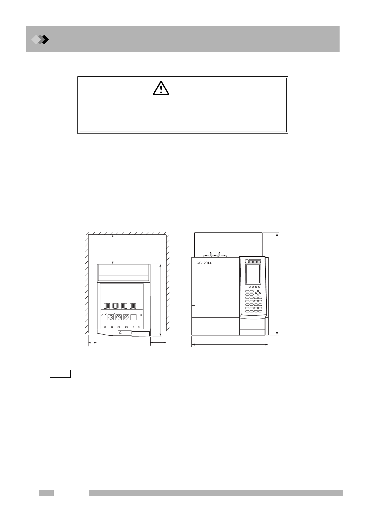
■ Installation clearances
Hot air is exhausted from the vent. Do not place flammable materials
where they will be exposed to the heat.
Hot air is vented at the back of the unit when the column oven cools. Consider the following
during installation.
1. Do not place flammable materials behind the unit.
2. Allow a clearance of 400 mm or more between the back cover and the wall.
3. Allow a clearance of 50 mm or more on the left side.
4. Allow a clearance of 100 mm or more on the right side in order to have a space to open/
close the oven door.
5. Reserve extra space for maintenance and inspection behind the unit.
WARNING
Hot air
NOTE
Minimum 400 mm
Height 690 mm
Depth 607 mm
Width 400 mm
Minimum 100 mmMinimum 50 mm
When the optional exhaust air duct (P/N 221-70675-91) is used, rear space of 200 mm or more is
required.
2
GC-2014
Page 15
■ Moving the GC
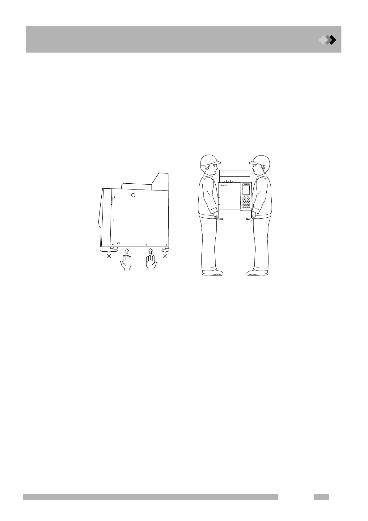
Move the GC carefully so it does not get bumped or jarred.
1. The GC weighs approximately 50 kg (GC-2014ATF).
2. Two people must carry the GC, one on the left and one on the right, with their hands
between the rubber legs on the left and right side of the unit.
3. Do not hold the oven door when carrying the GC because it may break the door.
4. Do not put your hands on the rubber legs or along the front/rear direction of the unit
because your fingers may get trapped under the unit when placing it on a table.
1 Installation
1.1 Verification of Installation Location
GC-2014
3
Page 16
1 Installation
1.2
1.
Before connecting the power supply, verify the following items.
Q Power supply voltage
Use a power source with the following specifications to maintain optimal unit performance.
1.2Power supply and wiring
WARNING
HIGH VOLTAGE
1.Before connecting the power cable to the distribution board, turn
OFF the power to the distribution board.
2.The power supply must have a circuit breaker.
3.Do not place heavy items on the power cable.
Commended power voltage: 115 VAC ± 5 %
230 VAC ± 5 %
Frequency 50/60 Hz
Operating power voltage: 115 VAC ± 10 %
230 VAC ± 10 %
Frequency 50/60 Hz
Q Power supply capacity
Calculate the power supply capacity by considering the total power consumption of the
individual components as shown below.
Connect the power source to a terminal with sufficient capacity.
GC-2014ATF (TCD, FID models):1,950 VA (115 V model)/2,750 VA (230 V model)
Optional temperature control block (INJ, etc.): 150 VA/pc
Maximum power is 2600 VA (115 V model), 3400 VA (230 V model)
NOTE
Q Connecting the power cable
NOTE
Performance of the unit may be affected if the power supply voltage fluctuates or the capacity is
insufficient.
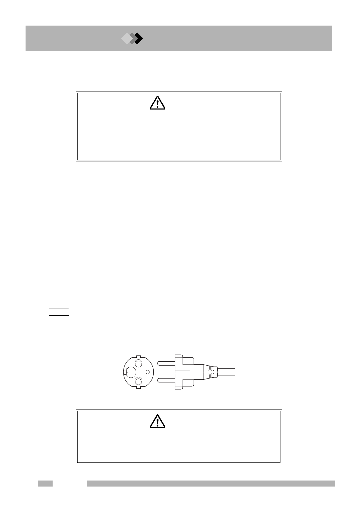
The power cable of the 230 V model uses a plug.
Fig. 1.2.1 Plug
WARNING
Make sure to ground the cable properly. Insufficient grounding may cause an
electric shock in the event of a breakdown.
Be careful to wire the plug correctly, as outlined on the next page to avoid
damage to the unit or supply fuse.
4
GC-2014
Page 17
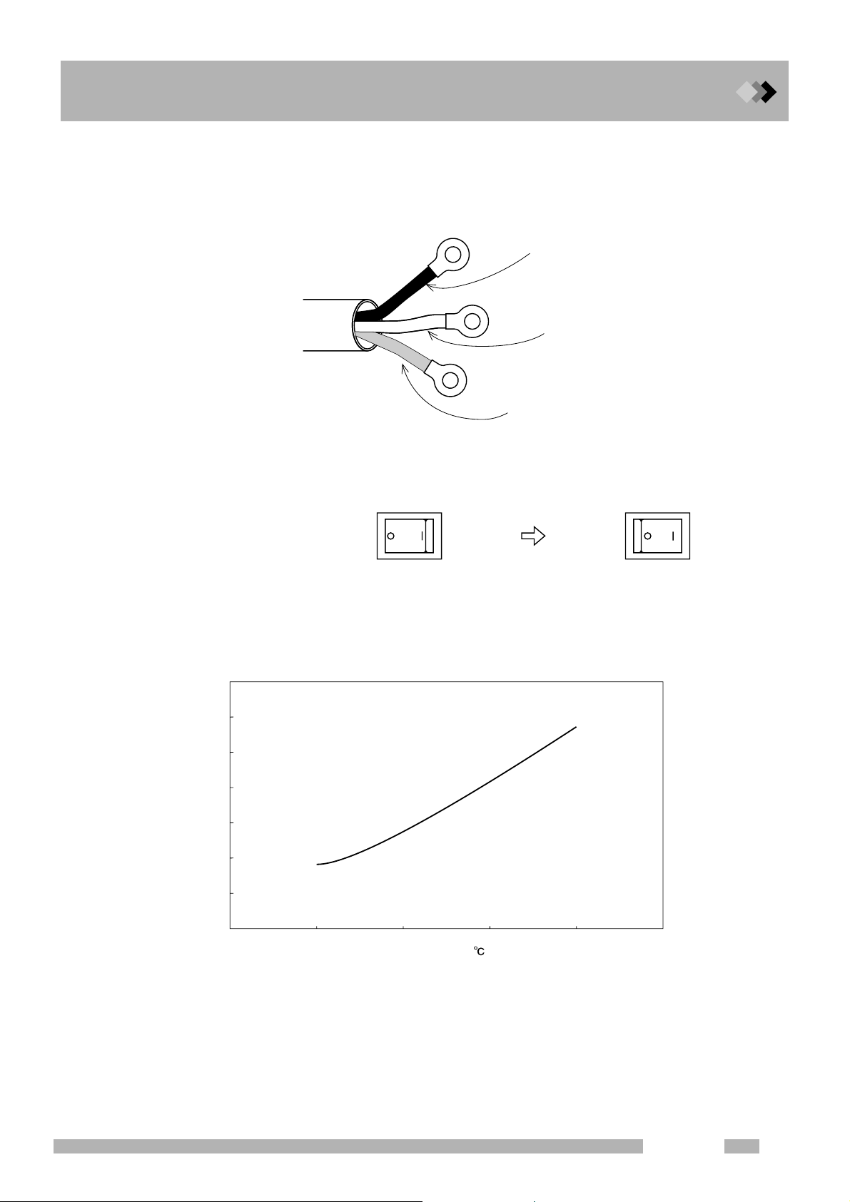
The power cable for 115 V model is color-coded as follows.
Black ... Connected to HOT of AC line.
White ... Connected to NEUTRAL of AC line.
Green ... Grounding (GROUND)
1 Installation
1.2 Power supply and wiring
Black
Power cable
Q Symbol conventions
~ : AC
○ : Off, Open
| : On, Close
Q Heating energy generation
The following graph shows the heating values generated by the unit.
3.5
3
Fig. 1.2.2 Power cable
OFF status
White
Green
Power switch
ON status
2.5
J/hour)
6
2
1.5
1
Heat generation (×10
0.5
0
0
100 200 300 400
Temperature (
)
Fig. 1.2.3
GC-2014
5
Page 18
1 Installation
1.2 Power supply and wiring
Q Fuse
The following fuses are used in the GC-2014.
Fuse, No.
F1, F2 15 A/250 V 10 A/250 V T
F3, F4 5 A/250 V 3.15 A/250 V T
F5, F6 5 A/250 V 5 A/250 V T
Rated current/voltage
Q Allowing the GC to dry after transport.
CAUTION
GC-2010 may get wet from humidity in some transport conditions. In
such case “drying-out” is necessary to avoid a short circuit at the
heater in the injection port or the detector.
Under some transport conditions, condensation may form inside the GC components. To
avoid injection port or detector heater unit short-circuits, allow the unit sufficient time to dry
after transport, and follow the procedure below after installation.
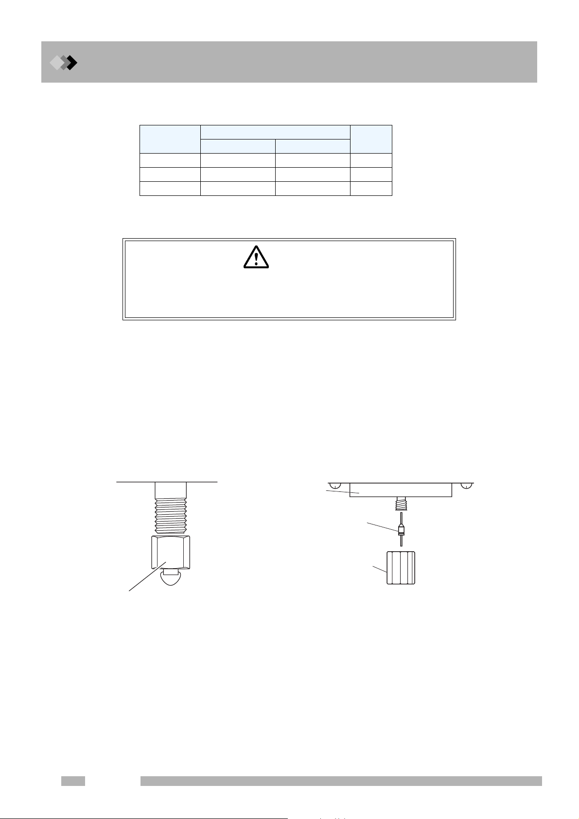
(1) Seal the injection port and detector without attaching a column. (Refer to the figure
below.)
(2) Remove the injection ports (INJ) and detectors (DET) from all configured analytical flow
lines to prevent the heater from turning ON.
(3) Set the column oven temperature to 300 °C and start the GC.
(4) Keep the column temperature at 300 °C for 2 hours or more.
Type *
∗Classification depending
on “IEC127”.115 V model 230 V model
2NWI
When a packed column connecting
joint is used
Thermal
insulation cup
Graphite ferrule
with a wire
Column nut
(or Column nut
of injection port)
When a capillary column connecting
joint is used
6
GC-2014
Page 19
1 Installation
1.3
1.
Q Supply gases
The following gases and associated purity values are required to maintain the optimum
performance of the unit.
For detectors other than FID and TCD, refer to the instruction manual corresponding to each detector.
1.3Gas Supply Plumbing
CAUTION
1.Gas supply pressure should not exceed the maximum pressure
listed below.
Excessive pressure may break pressure control valve or other parts.
2.When sharing a gas source with other instruments, check
specifications of all instruments to be used including this unit and
supply gas so that requirements of all the instruments can be
satisfied at the same time.
1. Gas types
•Carrier gas types
(Packed FID analysis)
Both helium and nitrogen can be used. Nitrogen is more reasonable in terms of price.
(Packed TCD analysis)
Using helium or hydrogen as carrier gas helps analyzing other materials at high
sensitivity. Because hydrogen is flammable, helium is generally used for safety.
However, to analyze helium or hydrogen, use nitrogen or argon as carrier gas. Nitrogen
is convenient to analyze minor components in the air because the nitrogen peak is not
detected when it is used as carrier gas.
(Capillary analysis)
Helium is the most suitable for separation.
Although nitrogen, which is more reasonable than helium, can also be used, the optimum
separation conditions may not be reached.
•Makeup gas types
(Capillary FID)
Both helium and nitrogen can be used. Nitrogen has a slightly higher sensitivity.
(Capillary TCD)
The same gas is used as makeup gas and reference gas for capillary TCD.
Select a type of gas by the same method to select carrier gas.
2. Gas purity
Helium (carrier gas, makeup gas) : 99.995 % or higher
Nitrogen (carrier gas, makeup gas) : 99.995 % or higher
Argon (carrier gas, makeup gas) : 99.995 % or higher
Hydrogen (FID detector gas) : 99.995 % or higher
Air (FID detector gas) : Dry air (oil and other organic components eliminated)
Compressed air(must be suppressed by an oil-free
compressor and dehumidified)
GC-2014
7
Page 20

1 Installation
1.3 Gas Supply Plumbing
3. Gas supply pressures
Carrier gas 300 - 980 kPa (Hydrogen: 300 - 500 kPa)
Makeup gas 300 - 980 kPa
Hydrogen 300 - 500 kPa
Air 300 - 500 kPa
NOTE
The relationship of kPa and bar is as follows
100 kPa = 1 bar
Convert units between kPa and kgf/cm2 as follows.
1 kPa = 1.0
1 kgf/cm2 = 98.1 kPa
Convert the units between kPa and psi as follows.
1 kPa = 1.45 × 10
1 psi = 6.89 kPa
2
× 10-2 kgf/cm
-1
2
psi
8
GC-2014
Page 21

Q High pressure gas cylinder precautions
WARNING
HIGH PRESSURE
Gas cylinders are under high pressure. When handling gas cylinders,
instruction and safety measures provided by the gas supplier must be
strictly observed to prevent accidents.
General precautions are provided below.
Consult state and local regulations for specific precautions.
Keep gas cylinders away from the lab, preferably outdoors, but not exposed to direct sunlight. The area must be well-ventilated. Use tubing to bring the gases to the lab.
The temperature of gas cylinders must not exceed 40 °C. Flammable items must be kept at
least 2 m from a gas cylinder.
When using high pressure gases, pay strict attention to ventilation, and perform daily leak
checks. In particular, when using flammable gases (such as hydrogen), never smoke or
allow open flame within 5 m of the equipment. Fire extinguishers must be present.
Secure gas cylinders firmly with cylinder clamps so they cannot fall over. Use oil-free pressure valves only. Never use tubing which has contacted oil. When finished with the gas,
tighten the main valve of the cylinder immediately.
1 Installation
1.3 Gas Supply Plumbing
GC-2014
9
Page 22
1 Installation
1.3 Gas Supply Plumbing
Q Precautions on handling hydrogen gas
WARNING
HYDROGEN GAS PRECAUTIONS
Hydrogen can explode if it is allowed to accumulate in a poorly ventilated area.
1.Connect gas lines correctly. Hydrogen is released into the room if
the tubing is accidentally connected to the air inlet.
2.When the unit is not in use, close the main valve of the hydrogen
gas cylinder. Check for leaks at the main valve.
3.Every time the unit is used, check for leaks along the flow line from
gas cylinder to the unit interior.
4.To prevent an explosion due to a hydrogen gas leak, the room in
which the unit is used should be well ventilated. Prohibit the use of
open flame in this room.
5.Close the main valve of the hydrogen cylinder immediately after
completing the analyses. Then, turn OFF the unit and perform
normal shut-down procedures.
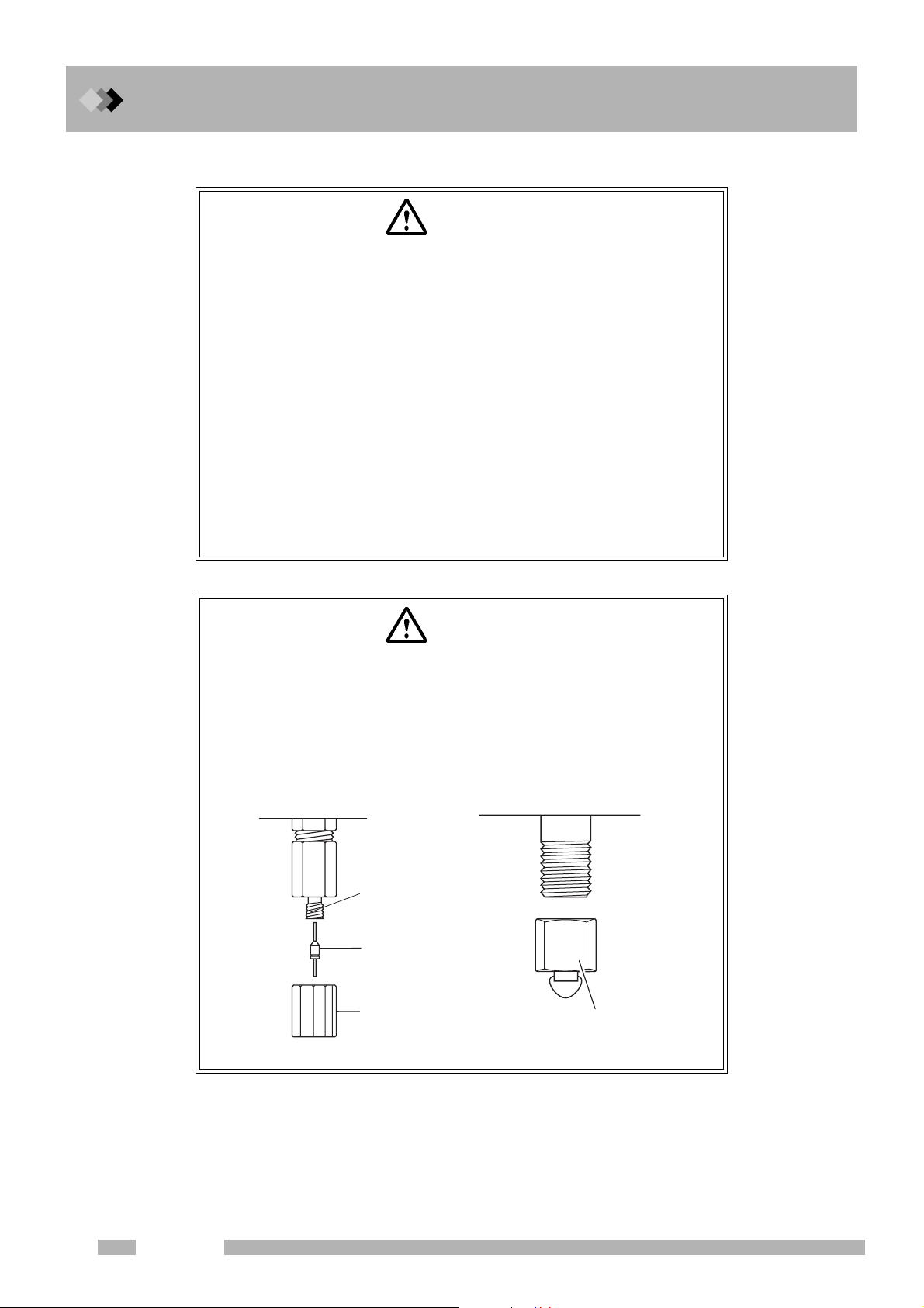
WARNING
HYDROGEN GAS HANDLING PRECAUTIONS
The accumulation of hydrogen gas inside the column oven can cause
an explosion.
Close all hydrogen regulator valves not in use and stop gas supply.
(When a manual regulator valve is used, turn its control to make the
pressure zero. For APC, turn off the APC for hydrogen gas.) Seal the
column connection.
Capillary adapter
Graphite ferrule
with a wire
Column nut
When a detector that uses hydrogen gas is not in use
Plug
10
GC-2014
Page 23
1.3 Gas Supply Plumbing
CAUTION
Hydrogen gas supply precautions
Make sure that the supply pressure to the flow controller does not
exceed 500 kPa.
If the flow controller fails with a hydrogen gas supply pressure over
500 kPa, a dangerous situation exists. Lange amounts of leaking
hydrogen could cause the FID flame to expand out of the detector.
Hydrogen gas is lighter than air. If it leaks, it can accumulate near the
ceiling. Pay strict attention to ventilation so that leaking hydrogen is
vented out of the room and cannot accumulate.
WARNING
1 Installation
Hydrogen carrier gas precautions
If much hydrogen gas is released into the poorly ventilated room, it
may cause the explosion.
1.In order to prevent hydrogen gas accumulate in the room, attach
tubes to split vent, purge vent, TCD vent and ECD vent. Discharge
the gas to open air or a ventilation equipment (such as the draft
chamber).
2.Install the GC in the well ventilated area. (Ex. in the draft chamber)
3.In order to measure hydrogen gas concentration, equip a hydrogen
gas sensor in the room. Keep the hydrogen concentration low.
GC-2014
11
Page 24
1 Installation
1.3 Gas Supply Plumbing
Q Supply gas tubing
There are two types connections in the Gas Chromatograph: Type M and Type G. Type M
connections are located at the main tubing connections in the instrument interior and exterior. The metal fittings contact directly.
Type G connectors, which are used in high temperature areas, are connected by tightening
three to five aluminum gaskets between the fittings.
MF fitting
MM fitting
Fig. 1.3.1 Joining Type M fittings
GF fitting
Alminum gaskets (3-5 pcs)
GM fitting
Fig. 1.3.2 Joining Type G fittings
Tightening the tubing connections
To ol s
2 wrenches 10×12 (standard accessory)
Use the 12 mm wrench for Type M connections and the 10 mm wrench for type G
connections.
12
Fig. 1.3.3 Tightening the joints
GC-2014
Page 25
Q Tubing between the gas cylinder and gas chromatograph
Gas filter <option>
Gas
cylinder
1 Installation
1.3 Gas Supply Plumbing
Fig. 1.3.4 Tubing between the gas cylinder and gas chromatograph
Use tubing with a 3 mm O.D. and 2 mm I.D. between the gas cylinder and gas chromatograph.
The use of a gas filter is highly recommended. Contaminated tubing or poor quality gases
can interfere with baseline stability.
<Option> Gas filter (P/N 221-05619-01)
This absorbs organic compounds and moisture in the supply gas, improving its
purity. The filter can be regenerated by baking in the GC oven at 250 °C with
30 mL/min carrier gas purging the filter.
Capacity: Approx. 200 mL
Absorbent: Molecular sieve 5 A
Fig. 1.3.5 Gas filter
GC-2014
13
Page 26
1 Installation
1.3 Gas Supply Plumbing
Q Gas chromatograph tubing connections
Connections are provided on the rear panel of the unit for connecting external tubing.
They are labeled as follows.
Carrier gas ..................... CARRIER
(“L” and “R” mean the left and right side of dual INJ.)
Makeup gas ................... MAKE UP
Hydrogen ....................... HYDROGEN
Air .................................. AIR
Flow controller
for the dual FID
Right Left
14
AFC for SPL AFC for the dual INJ
Supply the carrier gas for the left inlet of the dual INJ to CARRIER L
and the carrier gas for the right inlet of the dual INJ to CARRIER R.
Fig. 1.3.6 Plumbing (Example of the GC-2014ATF+SPL model)
GC-2014
Page 27

Q Checking for gas leaks
After plumbing the unit, check for gas leaks according to the following guidelines.
(1) Open the main valve of the gas cylinder.
(2) Adjust the gas supply to the specified pressures.
(3) Check for leaks with leak detecting fluid (option) or soapy water on all connections.
Bubbles can be observed if a leak exists.
(4) If a leak is detected:
• Further tighten the connection, or retighten it.
• Replace the seal material.
(5) Wipe off the leak detecting fluid or soapy water using a wet cloth.
Electronic leak detectors can also be used for hydrogen and helium leaks.
<Option> “Snoop” Gas leak detecting fluid (P/N 670-11514)
1 Installation
1.3 Gas Supply Plumbing
LIQUID LEAK DE
Fig. 1.3.7 Leak detecting fluid
GC-2014
15
Page 28

1 Installation
1.3 Gas Supply Plumbing
This page is intentionally left blank.
16
GC-2014
Page 29
2 Before Use
2.1
2.2.
2.1Setting Analytical Flow Lines
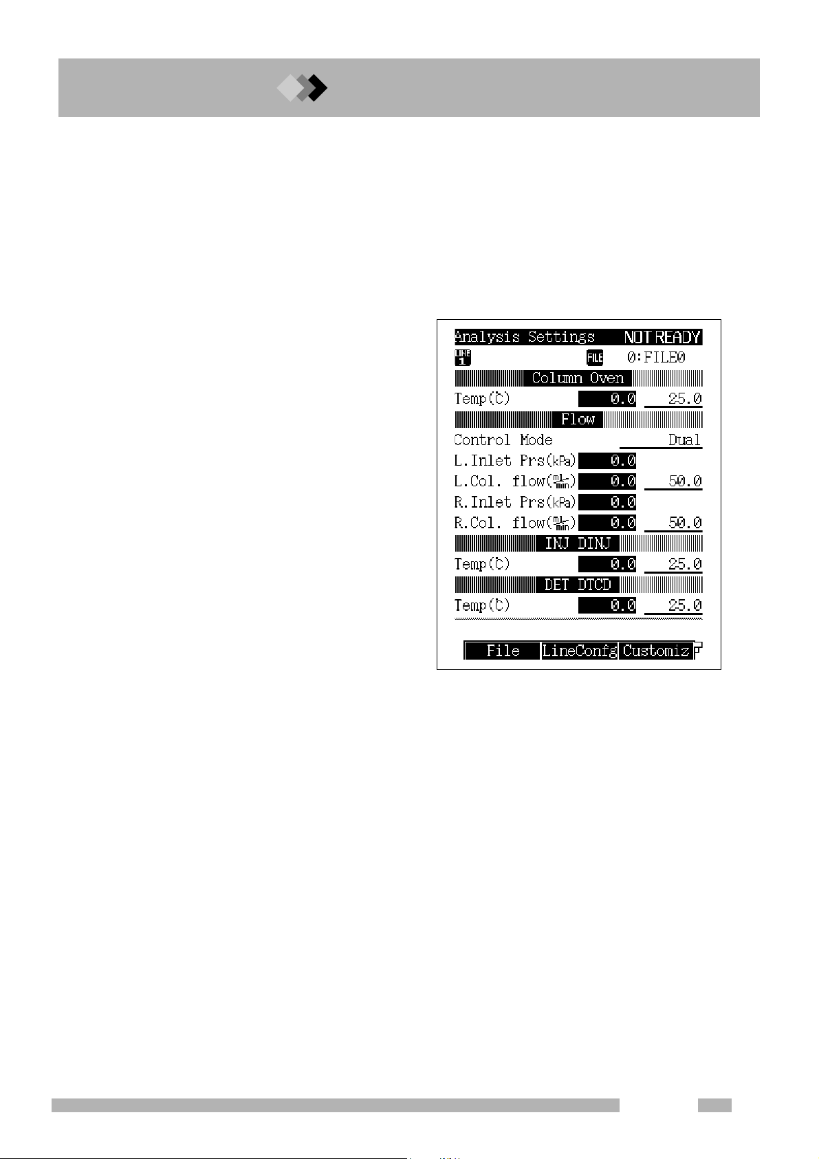
GC-2014 does not operate normally without setting analytical flow lines. Always set
analytical flow lines before using the unit. Refer to “Chapter 3. Installing Packed Columns
and Setting Analytical Flow Lines” and “Chapter 4. Installing Capillary Columns and Setting
Analytical Flow Lines” for detailed descriptions.
Setting analytical flow lines creates the following benefits during operation.
1. Conditions of analytical parameters for
each line can be set and monitored.
For example, when the [SET] key of
the gas chromatograph is pressed,
temperatures of columns, injection
ports, and detectors as well as carrier
gas flow rate can be set and monitored
on a single screen.
2. A protective mechanism operates to
foster more stable operation conditions.
For example, when a carrier gas
cylinder becomes empty while TCD is
used, the flow controller detects an
error and automatically lowers the
column temperature and stops
conduction to the TCD filament in order
to prevent damage to the column and
TCD filament.
GC-2014
17
Page 30
2 Before Use
2.1 Setting Analytical Flow Lines
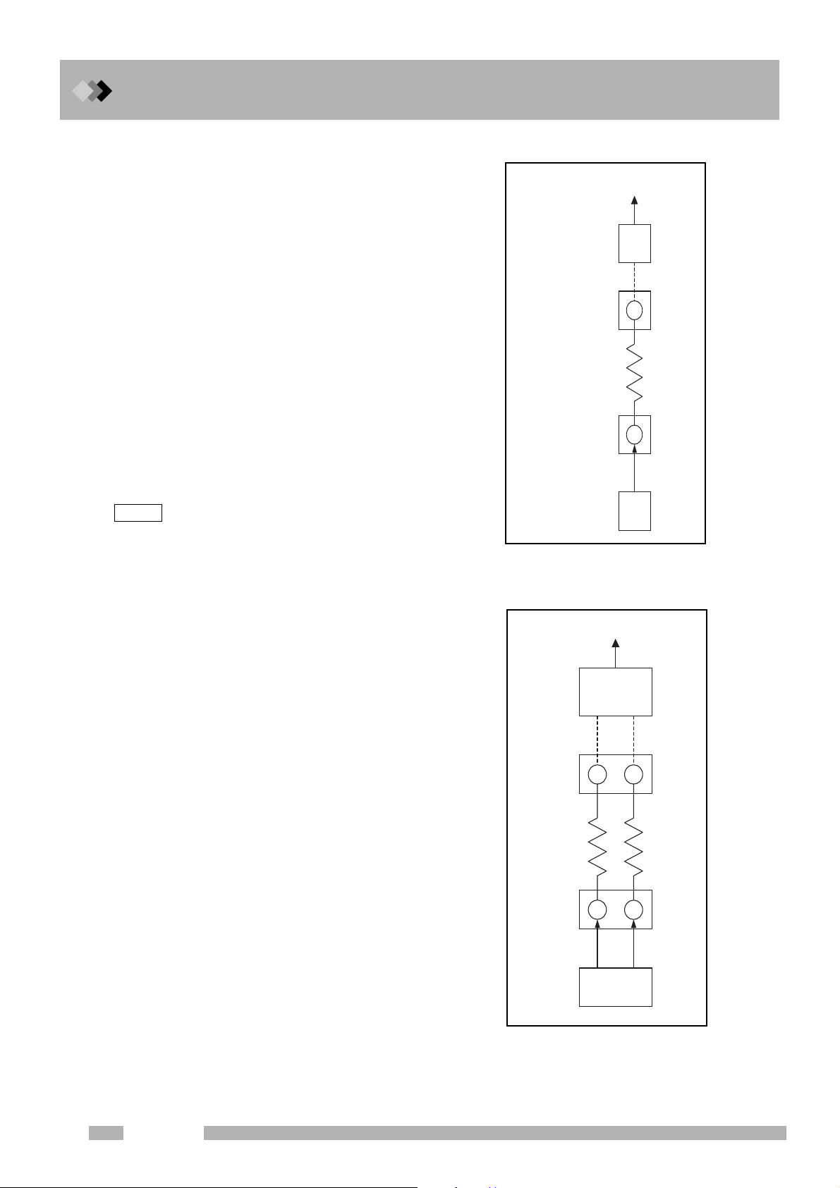
Q Analytical flow lines
An analytical flow line consists of the flow
controller, injection port, column, detector cell,
and detector amp as shown in Fig. 2.1.1.
During analysis, the flow controller feeds
carrier gas to the injection port, a sample
injected to the injection port goes through the
column to reach to the detector cell, and a
detected signal is amplified by the detector
amp to be outputted.
In order to allow the gas chromatograph to
recognize these units as an analytical flow line,
specification for the connection between them
is necessary.
For regular analysis, specify the combination
between an injection port and detector to
which a column is connected. (Refer to the
following page for setting procedures.)
Outputted Signal
Detector
amp
Detector
cell
Column
Injection
port
NOTE
Connections of the flow controller(s) and injection
port(s) and connections of detector cell(s), and
detector amplifier(s) are specified by a serviceperson
at shipment or installation. They do not need to be
specified for regular analysis.
Fig. 2.1.2 shows a representative example of
the line configuration for packed column FID
analysis using the GC-2014.
In this example, the dual INJ and dual FID are
connected with two columns and the difference
between two FID signals is outputted from the
dual FID amp. Two columns are used because
the dual INJ and dual FID are recognized as a
single unit respectively. However, this is
considered to be a single line.
flow
comtrol
Fig. 2.1.1 Concept of
analytical flow lines
Outputted Signal
Dual FID
amp
Dual FID
Column(L) Column(R)
Dual INJ
L R
L
R
18
GC-2014
Dual AFC
(L) (R)
Fig. 2.1.2 An example of
analytical flow lines
Page 31

■ How to set lines
(1) Press the [SET] key then press the
[PF2] key (Line Config).
(2) Move the cursor to the unit to be set in a
line and select a line using [
Make sure to specify an injection port
and a detector to which a column is
connected in the same line. Any
number from LINE1 through LINE4 can
be selected.
2 Before Use
2.1 Setting Analytical Flow Lines
Y ] [ Z ] keys.
■ Precautions for setting analytical flow lines
CAUTION
Set analytical flow lines correctly.
Incorrectly set analytical flow lines hinder the unit's normal operation
and may also damage columns or detectors at worst.
1. Specify units to be used as part of a line.
Only units specified as part of a line are temperature-regulated.
Gas is controlled only for injection ports (flow controllers) specified as part of a line.
Examples
• If an injection port that a column is connected is not specified as part of a line, carrier
gas does not flow. If the column's temperature rises in this condition, the column may be
damaged.
• To keep feeding gas to units or maintain their temperature even though they will not be
used for analysis for a while, specify the units as part of a line.
2. Remove the units not in use from a line.
Examples
• If a detector without a column stays on a line, it may damage TCD filament or cause an
error such as FID ignition error.
• If the setting for the flow controller is turned OFF without removing an injector port
without a column from a line, an error is detected and the protection mechanism works
to lower the column temperature.
• If a split/splitless injection port (SPL) without a column is not removed from a line, an
error is detected and the protection mechanism works to lower the column temperature.
GC-2014
19
Page 32

2 Before Use
A
A
2.2
2.2
2.
GC-2014 can output analog signals for two channels, and detector signals to be outputted to
each channel can be set using keys. When a detector is changed, output can be changed
using keys without changing the connection on the back of the GC.
■ Connecting the Chromatopac signal cable
Connect the attached Chromatopac signal cable to the connector (ANALOG OUT1 or 2) on
the back of the GC. (Fig. 2.2.1)
Using this cable, analog signals can be outputted and the Chromatopac can be started when
the GC starts. (Refer to “16.6.9 Setting the link device code”)
Outputting Analog Signals to the Chromatopac
NALOG OUT 1=Ch1
NALOG OUT 2=Ch2
Fig. 2.2.1 Connecting the Chromatopac signal cable
1
2
3
4
5
6
232C
-
RS
EVENT
OPTION
AOC
ANALOG
OUT 1
ANALOG
OUT 2
START IN
READY OUT
START OUT
AOC POWER SUPPLY
OUT/READY IN
232C OP1 LINKSTART
RS
INJECIOR1 INJECIOR2 SAMPLER
Back of the GC
AOC built-in power source
20
GC-2014
Page 33

■ Setting analog signal output
1. Set a line
(1) Press the [SET] key then press the
[PF2] key (Line Config).
(2) Specify an injection port and detector
to which a column is connected in the
same line.
The screen on the right shows an
example where a column is connected
to the dual INJ and dual FID.
2 Before Use
2.2 Outputting Analog Signals to the Chromatopac
NOTE
Without specifying a detector in a line, the screen to set analog signal output below does not appear.
2. Set analog signal output.
(1) Press the [DET] key.
(2) The outlined part is a parameter for
analog signal output for all detectors.
Set the parameter following the
description below.
For “Background signal save/
compensation” and “Detector signal
subtraction,” refer to “Chapter 13
Detector [DET].”
“Signal Output Port”
Specify a connector number to output
analog signals.
(ANALOG OUT 1 = Ch1, ANALOG OUT 2 = Ch2)
Channel number of a detector specified at
the last is effective. (If TCD signal was
outputted to Ch1 formerly and FID signal is
newly specified to be outputted to Ch1 as
shown in the screen on the right, TCD
signal becomes OFF automatically.)
GC-2014
21
Page 34

2 Before Use
2.2 Outputting Analog Signals to the Chromatopac
“Signal Attenuation” or “Signal Range”
Names of items automatically change according to types of analog signals as listed below.
Set multiplying power (attenuation rate) of output signals for all types. Change the setting
when the peak obtained by the data processing unit is saturated.
Signal attenuation: When analog signal type is wide
Output signal becomes smaller when the setting is changed from x 1
→ x 2
-3
→ x 2
-4
Signal range: When analog signal type is linear
Output signal becomes smaller when the setting is changed from x1
→ x 10
-3
→ x 10-4
“Analog Signal Type”
Set a signal type according to the type of Chromatopac to be connected. If this is set
incorrectly, data cannot be processed correctly.
Wide : C-R8A, C-R7A, C-R7Aplus
Linear: Chromatopacs other than C-R8A, C-R7A, C-R7Aplus
■ Calibration of analog wide range signal
When the GC is connected to the Chromatopac (C-R8A, C-R7A, C-R7Aplus) with a
chromatopac signal cable and the “analog signal type” described above is set to “Wide
calibration is necessary in order to match the zero level of the GC and Chromatopac.
-1
→ x 2
→ x10-1→ x10
→ x 2
-2
-2
,”
Perform calibration in the following cases.
• When the GC and Chromatopac are connected for the first time (during installation)
• When the GC or Chromatopac is changed with other instrument.
• When a connection channel number is changed by switching a connector on the GC side
• When a two-channel board is installed on the Chromatopac and a connection channel
number is changed by switching a connector on the Chromatopac side
NOTE
Calibration is not necessary when a detector is changed (e.g. when signal to be outputted to Ch1 is
changed from TCD to FID).
The following is calibration procedures.
(1) Press the [DET] key on the GC to turn OFF the detector control.
(2) Load the BASIC calibration program.
C-R7A, C-R7Aplus: Type “LOAD “ZCALIB”” on the [Win3] key screen.
C-R8A: Type “LOAD “8.ZCALIB.BAS”” when key input is possible.
(3) Press the [RUN] key of the Chromatopac.
(4) Enter the Chromatopac channel number
when the following sentence is displayed.
C-R7A, C-R7Aplus: “Channel No. (1:CH1 2:CH2) : ?”
C-R8A: “CH No. (1:CH1 2:CH2) : ?”
(5) Enter “Y” when the sentence below is displayed to save calibration results on the
Chromatopac. If they are not saved on the disk, calibration is required again when
starting the Chromatopac after turning its power off.
C-R7A, C-R7Aplus: “Save to disk (Y: Yes N: No) : ?”
C-R8A: “Save to the disk (Y: Save N: No) : ?”
(6) Press the [DET] key of the GC to turn ON the detector control.
22
GC-2014
Page 35

2 Before Use
2.3
2.
2.3Outputting Digital Signals to a Personal
Computer
GC-2014 can be directly connected to a personal computer to output digital signals.
GCsolution software allows a PC to control the unit and take data.
For operation of GCsolution, refer to its instruction manual.
■ Connecting the RS-232C cable
Connect the RS-232C cable attached to GCsolution workstation to the connector on the
back of the GC. (Fig. 2.3.1)
To connect one PC with more than one GCs, separate RS-232C cables are necessary and
an expanded COM port needs to be attached to the PC.
NOTE
AOC built-in power source has the same connector. Connect the cables correctly.
RS-232C
AOC POWER SUPPLY
Back of the GC
1
2
3
4
5
6
232C
-
RS
EVENT
OPTION
AOC
ANALOG
OUT 1
ANALOG
OUT 2
START IN
READY OUT
START OUT
OUT/READY IN
232C OP1 LINKSTART
RS
INJECIOR1 INJECIOR2 SAMPLER
AOC built-in power source
Fig. 2.3.1 Connection of RS-232C cable
GC-2014
23
Page 36

2 Before Use
2.3 Outputting Digital Signals to a Personal Computer
■ Setting transmission parameters
(1) Select “6. GC CONFIGURATION” on
the [FUNC] key screen and then select
“3. TRANSMISSION PARAMETER.”
(2) Set transmission parameters.
Protocol = LEVEL3
Baud rate (bps) = 115200
(3) Press the [PF2] key (Apply).
NOTE
Turning ON the power of the GC is not
necessary.
24
GC-2014
Page 37

2 Before Use
2.4
2.
2.4Connecting a RS-232C Cable to the
Chromatopac C-R8A
Connecting the GC-2014 and Chromatopac C-R8A with a RS-232C cable allows for various
functions such as printing out parameters of the GC.
For detailed information about C-R8A, refer to its instruction manual.
■ Connecting RS-232C cable
Connect an optional RS-232C cable to the connector on the back of the GC. (Fig. 2.4.1)
NOTE
AOC built-in power source has the same connector. Connect the cables correctly.
AOC POWER SUPPLY
RS-232C
1
2
3
4
5
6
232C
-
RS
EVENT
OPTION
AOC
ANALOG
OUT 1
ANALOG
OUT 2
START IN
READY OUT
START OUT
OUT/READY IN
232C OP1 LINKSTART
RS
INJECIOR1 INJECIOR2 SAMPLER
Back of the GC
AOC built-in power source
Fig. 2.4.1 Connection of RS-232C cable
GC-2014
25
Page 38

2 Before Use
2.4 Connecting a RS-232C Cable to the Chromatopac C-R8A
■ Setting transmission parameters
Set transmission parameters when performing digital-transmission between the GC and
Chromatopac for the first time. (This is not required for each operation.)
1. Set transmission parameters for the GC
(1) Select “6. GC CONFIGURATION” on
the [FUNC] key screen and then select
“3. TRANSMISSION PARAMETER.”
(2) Set transmission parameters.
Protocol = LEVEL2
Baud rate (bps) = 9600
Stop bit = 1 bit
Parity = EVEN
(3) Press the [PF2] key (Apply).
NOTE
Turning ON the power of the GC is not
necessary.
2. Set transmission parameters for the C-R8A
(1) Press the [CONFIG] key and then press the [T] key (T:TRS).
(2) Press the [ ↓ ] key until the STD2 Port (RS-232C) Setup screen appears.
[PORT | MODE | #No. | BPS ]
STD2 | 12917 | 8 | 9600
(3) Set transmission parameters.
MODE = 12917 (Protocol LEVEL2, Stop bit 1 bit, Parity EVEN)
#No. = 8 (logical port number)
BPS = 9600 (baud rate)
(4) After completing setting, press the [EXIT] key and then press the [Y] key to save the
settings.
(5) After changing transmission parameters, reboot the C-R8A to enable the new settings.
■ Procedures to start digital transmission
After setting transmission parameters, start digital transmission.
1. Start digital transmission.
(1) Type “OPEN TRS 8” using the C-R8A keyboard and press the [Enter] key.
(2) The transmission port will open and transmission between the GC and C-R8A will start.
NOTE
26
To turn OFF the power of the GC or Chromatopac after opening the transmission port, type “CLOSE
TRS 8” using the C-R8A keyboard and press the [Enter] key.
GC-2014
Page 39

2 Before Use
2.5
2.
2.5Connecting Auto Injector/Auto Sampler
AOC-20 Series
Connecting the GC-2014 and the auto injector/auto sampler power source unit using an
AOC RS-232C cable allows AOC parameters to be set using the GC’s keyboard.
Refer to AOC-20 user’s manual for details about AOC-20.
■ Cable connections
Connect the READY/START cable attached to the AOC built-in power source and the AOC
RS-232C cable to the connectors on the back of the GC. (Fig. 2.5.1)
Connect the AOC power cable to the connector on the back of the GC and the auto injector
or auto sampler.
NOTE
There are two identical RS-232C connectors. Make sure to make the correct connections.
READY/START cable
Wire the cables according to the
numbers on them. Press the
buttons on the terminal when
inserting or removing cables.
ButtonCable inlet
1
2
3
4
5
6
AOC RS-232C cable
Connect the cable to the "AOC"
connector and "RS-232C"
connector on the AOC built-in
power source.
Fig. 2.5.1 Connection of the AOC-20 series
1
2
3
4
5
6
232C
-
RS
EVENT
OPTION
AOC
ANALOG
OUT 1
ANALOG
OUT 2
START IN
READY OUT
START OUT
AOC POWER SUPPLY
OUT/READY IN
232C OP1 LINKSTART
RS
INJECIOR1 INJECIOR2 SAMPLER
Back of the GC
SMAPLER=auto sampler
AOC power cable
INJECTOR1=auto injector
AOC built-in power source
GC-2014
27
Page 40

2 Before Use
2.5 Connecting Auto Injector/Auto Sampler AOC-20 Series
■ Setting AOC parameters
1. Set a line.
(1) Press the [SET] key and then press the
[PF2] key (Line Config).
(2) Specify “AOC1” on the line with the
injection port that the auto injector has
been attached to.
(3) The GC and AOC built-in power source
will be automatically linked.
2. Set AOC parameters.
(1) Press the [OPTION] key. If other option
screens appear, press the [OPTION]
key repeatedly until the AOC
Parameter screen appears.
(2) Set AOC parameters.
Parameters will be transmitted to the
AOC as soon as they are set.
NOTE
For detailed information about setting AOC
parameters, refer to
Parameters”
If the AOC Parameter screen is not
displayed, check the connection of RS232C cable and settings for line
configuration.
or AOC-20 user’s manual.
“15.1 Auto Injector
28
GC-2014
Page 41

2 Before Use
2.6
2.
2.6Connecting the Relay Terminals
By using the optional relay cable (P/N221-48568-91), relay that operates according to event
commands can be used.
For detailed information about setting events, refer to “16.3 Time Program” or “16.5 Direct
Operation”.
For example, if the cable is connected to COM and NO found in Fig. 2.6.1, they are
connected by EVENT91 and disconnected by EVENT-91. If it is connected to COM and
2
NC, they will be connected by EVENT-91 and disconnected by EVENT91.
1 3
AOC POWER SUPPLY
OUT/READY IN
1
Back of the GC
EVENT91
EVENT92
COM
NC
NO
COM
NC
NO
㧝
㧞
㧟
㧠
㧡
㧢
(Red)
(White)
(Black)
(Yellow)
(Blue)
(Green)
1
2
3
4
5
6
232C
-
RS
EVENT
OPTION
AOC
ANALOG
OUT 1
ANALOG
OUT 2
START IN
READY OUT
START OUT
232C OP1 LINKSTART
RS
INJECIOR1 INJECIOR2 SAMPLER
Fig. 2.6.1 Connecting a relay cable
AOC built-in power source
GC-2014
29
Page 42

2 Before Use
2.6 Connecting the Relay Terminals
This page is intentionally left blank.
30
GC-2014
Page 43

3 Installing Packed Columns and Setting Analytical Flow Lines
3.1
3.3.
Injection ports and detectors for packed columns can be installed in positions described in
Table 3.1.1 and Fig. 3.1.1.
Injection ports
Detectors
Installation location numbers indicate the positions of column connecting joints.
3.1Installation Location for Packed Columns
Table 3.1.1 Installation location for injection ports/detectors for packed columns
Name Possible installation location
Dual INJ 1-2, 2-3, 3-4
Single INJ 1, 4
Dual FID 6-7
TCD 9-10
Single DET 5, 6, 7, 8
Fig. 3.1.1 Fig. 3.1.1 Installation location for injection ports/detectors for packed
columns (layout viewed from the top of the unit)
GC-2014
31
Page 44

3 Installing Packed Columns and Setting Analytical Flow Lines
3.1 Installation Location for Packed Columns
Check which units the joints found on the column oven correspond to.
Fig. 3.1.2 shows the layout for the GC-2014ATF+SPL model.
Left and right sides viewed from the front of the unit are indicated as L (left) and R (right)
respectively.
SPL
Dual INJ
.4
LR
Dual FID
.4
TCD
Fig. 3.1.2 Column connecting joints (GC-2014ATF+SPL model)
32
GC-2014
Page 45

3 Installing Packed Columns and Setting Analytical Flow Lines
3.2
3.
NOTE
3.2Dual-Column Packed FID Analysis
Connecting the left (L) sides and right (R) sides of the dual INJ and dual FID with columns
respectively allows for analysis with the dual-column configuration.
Dual-column configuration is used in following cases.
1. Same type of columns are connected to the left and right sides in order to backgroundcompensate the increase of the baseline during programmed temperature analysis.
2. Different types of columns are connected to the left and right sides in order to obtain a
different chromatogram when a sample is injected to the left (L) side and right (R) side
of the dual INJ.
Do not cross the columns (L/R). It hinders correct analysis.
Dual FID
L R
Column (L) Column (R)
Dual INJ
Dual AFC
Fig. 3.2.1 Dual-column configuration
L
(L) (R)
R
GC-2014
33
Page 46

3 Installing Packed Columns and Setting Analytical Flow Lines
3.2 Dual-Column Packed FID Analysis
■ Setting analytical flow lines
Setting analytical flow lines is described below.
For procedures to install columns and input analytical conditions, refer to the operation
manual.
1. Set a line.
(1) Press the [SET] key and then press the [PF2] key (Line Config).
(2) Set the dual INJ (DINJ) and dual FID (DFID) on a same line.
LINE1 is specified in the example below. Lines 1 through 4 can be selected.
2. Set the dual AFC.
(1) Press the [FLOW] key.
(2) Set “Control mode” to “Dual.”
34
GC-2014
Page 47

3. Set the dual FID.
(1) Press the [DET] key.
(2) Set “Control mode” to “Dual.”
(3) Set “Signal polarity” as described below.
+
: The FID (L) - FID (R) signal is outputted.
(When a sample is injected into the dual INJ (L))
-
: The FID (R) - FID (L) signal is outputted.
(When a sample is injected into the dual INJ (R))
3 Installing Packed Columns and Setting Analytical Flow Lines
3.2 Dual-Column Packed FID Analysis
GC-2014
35
Page 48

3 Installing Packed Columns and Setting Analytical Flow Lines
3.3
3.
NOTE
3.3Single-Column Packed FID Analysis
Connecting either of the left (L) sides or right (R) sides of the dual INJ and dual FID with a
column allows for analysis with the single-column configuration.
Single-column configuration is used in following cases.
1. Background-compensation is unnecessary because the baseline level does not
increase during isothermal analysis.
2. Background-compensation is unnecessary because the baseline level does not
increase so much even during programmed temperature analysis.
1. When single-column configuration is set, unspecified flow controller does not supply gases. Make
sure to remove unspecified column to prevent deterioration.
2. Make sure to stop the FID detector gas supply (hydrogen and air) on unspecified side. (Turn the
control of the flow controller to set the pressure to zero.)
3. Do not cross the columns (L/R). It hinders correct analysis.
Dual FID
L R
Column (L)
Dual INJ
Dual AFC
Fig. 3.3.1 Single-column configuration (FID)
(A column is connected to the left (L) sides.)
L
(L) (R)
R
36
GC-2014
Page 49

■ Setting analytical flow lines
Setting analytical flow lines is described below.
For procedures to install columns and input analytical conditions, refer to the operation
manual.
1. Set a line.
(1) Press the [SET] key and then press the [PF2] key (Line Config).
(2) Set the dual INJ (DINJ) and dual FID (DFID) on a same line.
LINE1 is specified in the example below. Lines 1 through 4 can be selected.
3 Installing Packed Columns and Setting Analytical Flow Lines
3.3 Single-Column Packed FID Analysis
2. Set the dual AFC.
(1) Press the [FLOW] key.
(2) Set “Control mode” as described below.
Set to “Single L” when the column is connected to the left (L) side of the dual INJ and “Single
R” when it is connected to the right (R) side.
GC-2014
37
Page 50

3 Installing Packed Columns and Setting Analytical Flow Lines
3.3 Single-Column Packed FID Analysis
3. Set the dual FID.
(1) Press the [DET] key.
(2) Set “Control mode” as described below.
Set to “Single L” when the column is connected to the left (L) side of the dual FID and “Single
R” when it is connected to the right (R) side.
38
GC-2014
Page 51

3 Installing Packed Columns and Setting Analytical Flow Lines
3.4
3.
3.4Packed TCD Analysis
Connecting the left (L) sides and right (R) sides of the dual INJ and TCD with columns
respectively allows for analysis with the dual-column configuration.
Dual-column configuration is used in following cases.
1. Almost equal columns are connected on the left and right sides to balance TCD's zero
point for analysis.
2. Different types of columns are connected to the left and right sides in order to obtain a
different chromatogram when a sample is injected to the L and R of the dual INJ.
TCD
L
R
Column (L) Column (R)
NOTE
Dual INJ
Dual AFC
Fig. 3.4.1 Dual-column configuration (TCD)
1.Carrier gas has to be fed to both of left and right (L/R) sides of the
TCD. Using the TCD without carrier gas will damage the filament.
2.During analysis with a single column, connect a pipe to the other
flow path instead of a column and feed carrier gas.
1. Do not cross the columns (L/R). It hinders correct analysis.
2. If left and right columns are extremely different (e.g. liquid quantity, flow rate), zero point may not be
achieved by turning the control on the right side of the GC unit. In this case, adjust the column flow
rate on the side that a sample is not analyzed (reference side).
L
(L) (R)
R
CAUTION
GC-2014
39
Page 52

3 Installing Packed Columns and Setting Analytical Flow Lines
3.4 Packed TCD Analysis
■ Setting analytical flow lines
Setting analytical flow lines is described below.
For procedures to install columns and input analytical conditions, refer to the operation
manual.
1. Set a line.
(1) Press the [SET] key and then press the [PF2] key (Line Config).
(2) Set the dual INJ (DINJ) and TCD (DTCD) on a same line.
LINE1 is specified in the example below. Lines 1 through 4 can be selected.
2. Set the dual AFC.
(1) Press the [FLOW] key.
(2) Set “Control mode” to “Dual.”
40
GC-2014
Page 53

3. Set the TCD.
(1) Press the [DET] key.
(2) Set “Signal polarity” as described below.
+
-
3 Installing Packed Columns and Setting Analytical Flow Lines
3.4 Packed TCD Analysis
: The TCD (L) - TCD (R) signal is outputted.
(When a sample, which a plus peak is detected, is injected into the dual INJ (L))
: The TCD (R) - TCD (L) signal is outputted.
(When a sample, which a plus peak is detected, is injected into the dual INJ (R))
NOTE
TCD signals do not necessarily have a plus peak because they are determined by relationship of heat
conduction between a substance to be analyzed and carrier gas. However, the data processing unit
normally calculates the area of a plus peak. When a minus peak is detected, “signal polarity” needs to
be inverted into a plus peak. In this case, inject a sample into the opposite inlet of the one instructed on
the popup screen shown below.
“Signal polarity” can be changed using the time program during analysis. (For detailed descriptions
about setting the time program, refer to
“16.3 Time Program”)
GC-2014
41
Page 54

3 Installing Packed Columns and Setting Analytical Flow Lines
3.5
3.
3.5Packed Analysis Using the Single DET
To perform glass packed column analysis using the unit with the single DET (single FID,
ECD, FPD, and FTD for packed analysis), move the dual INJ to the front of the single DET
prior to connecting a column.
Dual FID/TCD
L R
Dual INJ
Single DET
Column
L
R
NOTE
Dual AFC
Fig. 3.5.1 Single DET configuration
1. When a SUS column is used, the dual INJ does not need to be moved.
2. If the single packed INJ is installed in front of the single DET, analysis can be performed without
moving the dual INJ. For detailed descriptions, refer to instruction manual of the single packed INJ.
Dual INJ is set on the single mode so carrier gas is not fed to the
unspecified port (L on the figure above). Do not connect a column to
the port.
(L) (R)
CAUTION
42
GC-2014
Page 55

3 Installing Packed Columns and Setting Analytical Flow Lines
■ Procedures to move the dual INJ
Carry out the procedures after the injection port becomes 40 °C or
less to prevent burns.
Some insulation materials include ceramic fibers.
Refer to “When Handling Insulation” of “Introduction” in the GC-2014
Operation manual before you handle these materials.
When cutting a heat insulator, handle a cutting knife, etc. with care.
3.5 Packed Analysis Using the Single DET
WARNING
CAUTION
CAUTION
Move the dual INJ following the procedures below. Perform backward processes to return it
to its original position.
(1) Set the dual INJ temperature at room temperature or lower and wait until it becomes
40 °C or less.
(2) Turn OFF the power of the GC unit.
(3) Remove the column connected to the dual INJ.
(4) Detach wiring connected to the dual INJ in order to improve workability.
(5) Unfasten the three screws that fasten the dual INJ (Fig. 3.5.2 (a)) and pull the dual INJ
upward.
(Sems screws with a flat washer are used. Be careful not to drop flat washers.)
(6) Take out the heat insulator laid on the bottom of the dual INJ using tweezers or other
similar tools.)
Screws (sems screws + flat washers)
Fig.3.5.2 (a)
Dual INJ
Single DET
GC-2014
43
Page 56

3 Installing Packed Columns and Setting Analytical Flow Lines
3.5 Packed Analysis Using the Single DET
(7) Cut out the heat insulator using a cutting knife, etc. as shown in Fig. 3.5.2 (a).
(The heat insulator is approximately 3 cm thick. Cut the sheet metal on the bottom of the
heat insulator as well.)
(8) Move the cut heat insulator to the left.
50mm
Fig.3.5.2 (b)
(9) Insert the dual INJ on top of the heat insulator that has been taken out in step (6) and
fasten it with three screws. (Refer to Fig. 3.5.2 (c)).
(10) Connect the wiring that has been removed in step (4) to the dual INJ as it was originally.
Screws (sems screws + flat washers)
44
Fig.3.5.2 (c)
GC-2014
Page 57

■ Setting analytical flow lines
Setting analytical flow lines is described below.
For procedures to install columns and input analytical conditions, refer to the operation
manual.
1. Set a line.
(1) Press the [SET] key and then press the [PF2] key (Line Config).
(2) Set the dual INJ (DINJ) and single DET (PECD in the screen below) on a same line.
LINE1 is specified in the example below. Lines 1 through 4 can be selected.
3 Installing Packed Columns and Setting Analytical Flow Lines
3.5 Packed Analysis Using the Single DET
2. Set the dual AFC.
(1) Press the [FLOW] key.
(2) Set “Control mode” as described below.
Set to “Single L” when the column is connected to the left (L) side of the dual INJ and “Single
R” when it is connected to the right (R) side.
GC-2014
45
Page 58

3 Installing Packed Columns and Setting Analytical Flow Lines
3.5 Packed Analysis Using the Single DET
This page is intentionally left blank.
46
GC-2014
Page 59

4 Installing Capillary Columns and Setting Analytical Flow Lines
4.1
4.4.
Injection ports and detectors for capillary columns can be installed in positions described in
Table 4.1.1 and Fig. 4.1.1.
(Injection ports and detectors that can be used for packed columns are included.)
Injection ports
Detectors
Installation location numbers indicate the positions of column connecting joints.
4.1Installation Location for Capillary Columns
Table 4.1 Installation location for injection ports/detectors for capillary columns
Name Possible installation location
SPL 1, 4
WBI 1, 4
Dual INJ 1-2, 2-3, 3-4
Single INJ 1, 4
Dual FID 6-7
Single DET 5, 6, 7, 8
FTD-2014c 11, 12
TCD 9-10
Fig. 4.1.1 Installation location for injection ports/detectors for capillary columns
(layout viewed from the top of the unit)
GC-2014
47
Page 60

4 Installing Capillary Columns and Setting Analytical Flow Lines
4.1 Installation Location for Capillary Columns
Check which units the joints found on the column oven correspond to.
Fig. 4.1.2 (a) and (b) show the layout for the GC-2014ATF+SPL model and GC-2014AFsc
model. Left and right sides viewed from the front of the unit are indicated as L (left) and R
(right) respectively.
SPL
Dual INJ
.4
.4
Dual FID
.4
Dual TCD
Fig.4.1.2 (a) Column connecting joints (GC-2014ATF+SPL model)
52.
48
GC-2014
Single FID
Fig.4.1.2 (b) Column connecting joints (GC-2014AF
SC model)
Page 61

4 Installing Capillary Columns and Setting Analytical Flow Lines
4.2
4.
4.2Capillary Analysis Using the Dual FID
(When a detector adapter with purge is used)
To perform capillary analysis using a unit with the dual FID, makeup gas needs to be
supplied to the FID that a column is connected to.
In order to supply makeup gas, attach a detector adapter with purge (P/N 221-34012-91) to
the joint of the dual FID. Connect the purge piping of the adapter to the dual INJ so that
makeup gas is supplied from the dual AFC through the dual INJ.
(The dual AFC is off the line and operates as an independent mass flow controller.)
Although an adapter and column are connected to the right (R) sides of the dual INJ and
dual FID in the figure below, they can be connected to either side (L/R).
Dual FID
L
Column
R
Detector
adapter
with purge
SPL
AFC
Fig. 4.2.1 Dual FID (detector adapter)
L
(L) (R)
Dual AFC
R
Dual INJ
GC-2014
49
Page 62

4 Installing Capillary Columns and Setting Analytical Flow Lines
4.2 Capillary Analysis Using the Dual FID (When a detector adapter with purge is used)
■ Setting analytical flow lines
Setting analytical flow lines is described below.
For procedures to install an adopter and columns and input analytical conditions, refer to the
operation manual.
1. Change the dual AFC configuration.
(1) Select “6. GC CONFIGURATION” on the [FUNC] key screen and then select “9. Other
configuration.”
(2) Specify “AMC.LR” at “DAFC unit.”
2. Set a line.
(1) Press the [SET] key and then press the [PF2] key (Line Config).
(2) Set the SPL and dual FID (DFID) on a same line.
NOTE
If the dual AFC is specified for AMC.LR, the indication of DINJ disappears.
LINE1 is specified in the example below. Lines 1 through 4 can be selected.
50
GC-2014
Page 63

4.2 Capillary Analysis Using the Dual FID (When a detector adapter with purge is used)
3. Set the makeup gas flow rate.
(1) Press the [OPTION] key.
(2) Set AMC.L when the detector adopter is connected to the left (L) side of the dual INJ
and set AMC.R when it is connected to the right (R) side.
Start control and set the makeup gas flow rate and gas type.
4 Installing Capillary Columns and Setting Analytical Flow Lines
4. Set the dual FID.
(1) Press the [DET] key.
(2) Set “Control mode” as described below.
Set to “Single L” when the column is connected to the left (L) side of the dual FID and “Single
R” when it is connected to the right (R) side.
GC-2014
51
Page 64

4 Installing Capillary Columns and Setting Analytical Flow Lines
4.3
4.
4.3Capillary Analysis Using the Dual FID
(When a makeup gas flow controller is used)
To perform capillary analysis using a unit with the dual FID, makeup gas needs to be
supplied to the FID that a column is connected to.
In order to supply makeup gas, the optional makeup gas flow controller (P/N 221-70877-91:
1 flow path, 221-70877-92: 2 flow paths) are used.
Prior to installing a column, install the detector adapter (P/N 221-33193-91) to the detector's
joint.
Although an adapter and column are connected to the right (R) side of the dual FID in the
figure below, they can be connected to either side (L/R).
Dual FID
Hydrogen
L
Column
R
Flow controller
Makeup gas
Detector
adapter
SPL
AFC
Fig. 4.3.1 Dual FID (flow controller)
L
(L) (R)
Dual AFC
R
Dual INJ
52
GC-2014
Page 65

4.3 Capillary Analysis Using the Dual FID (When a makeup gas flow controller is used)
■ Setting analytical flow lines
Setting analytical flow lines is described below.
For procedures to install an adopter and columns and input analytical conditions, refer to the
operation manual.
1. Set a line.
(1) Press the [SET] key and then press the [PF2] key (Line Config).
(2) Set the SPL and dual FID (DFID) on a same line.
LINE1 is specified in the example below. Lines 1 through 4 can be selected.
4 Installing Capillary Columns and Setting Analytical Flow Lines
2. Set the dual FID.
(1) Press the [DET] key.
(2) Set “Control mode” as described below.
Set to “Single L” when the column is connected to the left (L) side of the dual FID and “Single
R” when it is connected to the right (R) side.
GC-2014
53
Page 66

4 Installing Capillary Columns and Setting Analytical Flow Lines
4.4
4.
4.4Capillary TCD Analysis
To perform capillary analysis using a unit with the TCD, makeup gas needs to be supplied to
the TCD joint that a column is connected to and carrier gas (called reference gas) also
needs to be supplied to the TCD joint that a column is not connected.
In order to supply makeup gas, install the detector adapter with purge (P/N 221-34012-91) to
the TCD joint. Connect the purge piping of the adapter to the dual INJ so that makeup gas is
supplied from the dual AFC through the dual INJ.
(The dual AFC is off the line and operates as an independent mass flow controller.)
Reference gas is supplied from the dual AFC when the dual INJ and TCD are connected
with a MF-MF joint.
TCD
LR
Detector
adapter
with purge
Column
MF-MF
piping
SPL
AFC
Fig. 4.4.1 Capillary TCD
The figure above shows an example where makeup gas and reference gas are connected to
the left (L) and right (R) sides of the dual INJ respectively and a column and reference gas
piping are connected to the left (L) and right (R) sides of the TCD respectively. They can be
connected to either side (L/R).
1.Carrier gas (makeup gas and reference gas) has to be fed to both
of left and right (L/R) sides of the TCD. Using the TCD without
carrier gas will damage the filament.
2.When makeup gas and reference gas are supplied from the dual
AFC, TCD filament's protection mechanism does not work even if
an error occurs.
L
(L) (R)
Dual AFC
CAUTION
R
Dual INJ
54
GC-2014
Page 67

■ Setting analytical flow lines
Setting analytical flow lines is described below.
For procedures to install columns and input analytical conditions, refer to the operation
manual.
1. Change the dual AFC configuration.
(1) Select “6. GC CONFIGURATION” on the [FUNC] key screen and then select “9. Other
configuration.”
(2) Specify “AMC.LR” at “DAFC unit.”
4 Installing Capillary Columns and Setting Analytical Flow Lines
4.4 Capillary TCD Analysis
2. Set a line.
(1) Press the [SET] key and then press the [PF2] key (Line Config).
(2) Set the SPL and dual TCD (DTCD) on a same line.
NOTE
If the dual AFC is specified for AMC.LR, the indication of DINJ disappears.
LINE1 is specified in the example below. Lines 1 through 4 can be selected.
GC-2014
55
Page 68

4 Installing Capillary Columns and Setting Analytical Flow Lines
4.4 Capillary TCD Analysis
3. Set the makeup gas/reference gas flow rates.
(1) Press the [OPTION] key.
(2) The left (L) side of the dual INJ corresponds to AMC.L and the right (R) side
corresponds to AMC.R. Start controlling both AMC.L and AMC.R and set the flow rates
and gas types according to the connection of detector adopter and reference gas
piping.
4. Set the TCD.
(1) Press the [DET] key.
(2) Set “Signal polarity” as described below.
+
-
: The TCD (L) - TCD (R) signal is outputted.
(When a column is connected to TCD (L) and a sample that a plus peak is
detected is injected)
: The TCD (R) - TCD (L) signal is outputted.
(When a column is connected to TCD (R) and a sample that a plus peak is
detected is injected)
56
GC-2014
Page 69

4 Installing Capillary Columns and Setting Analytical Flow Lines
4.4 Capillary TCD Analysis
NOTE
TCD signals do not necessarily have a plus peak because they are determined by relationship of heat
conduction between a substance to be analyzed and carrier gas. However, the data processing unit
normally calculates the area of a plus peak. When a minus peak is detected, “signal polarity” needs to
be inverted into a plus peak.
“Signal polarity” can be changed using the time program during analysis. (For detailed descriptions
about setting the time program, refer to “16.3 Time Program.”)
GC-2014
57
Page 70

4 Installing Capillary Columns and Setting Analytical Flow Lines
r
4.5
4.
4.5Single DET
To perform capillary analysis using a unit with the single DET (single FID, ECD, FPD, and
capillary FTD), makeup gas is used as described below.
Install the detector adapter to the detector joint then install a column. Detector adapter
comes with all single DET units listed above.
Single FID, ECD, and capillary FTD
A makeup gas flow controller comes with them.
FPD
Makeup gas is unnecessary.
Single DET
Hydrogen
Flow controller
Makeup gas
Column
Detecto
adapter
SPL
AFC
Fig. 4.5.1 Single DET (In case of FID)
58
GC-2014
Page 71

■ Setting analytical flow lines
Setting analytical flow lines is described below.
For procedures to install columns and input analytical conditions, refer to the operation
manual.
1. Set a line.
(1) Press the [SET] key and then press the [PF2] key (Line Config).
(2) Set the SPL and single DET (SFID in the screen below) on a same line.
LINE1 is specified in the example below. Lines 1 through 4 can be selected.
4 Installing Capillary Columns and Setting Analytical Flow Lines
4.5 Single DET
GC-2014
59
Page 72

4 Installing Capillary Columns and Setting Analytical Flow Lines
4.5 Single DET
This page is intentionally left blank.
60
GC-2014
Page 73

5 Analysis
5.1
5.5.
For detailed descriptions about analysis procedures, refer to the operation manual.
5.1Analysis Flow Chart
5.1.1 Preparation
Injection port preparation Select an injection port suitable to the sample injection method.
Confirm that the septum and insert are properly attached.
Check dirt on the septum and the number of injections and replace it
when necessary (after approximately 100 injections).
Column preparation Attach the column to the injection port and detector correctly.
When the above preparations are complete, turn ON the GC (power switch on the lower
right side of the GC).
5.1.2 Setting Parameters
Set the column information
and the flow rates column length, and the film thickness on [Column] (PF menu). For
Set parameters on the [FLOW] key screen. Set the column inner diameter,
the SPL and WBL, set the purge flow rate on [Purge] as well.
(When the column flow rate is set by the AFC, changing the column
temperature changes the column flow rate.)
Set the temperature of the
detector and the injection port is set to “Off,” turn it “On.”) When the APC is used, set hydrogen, air,
Set the COL temperature and From the screen of the [COL] key, set the column initial temperature
the temperature program and the temperature program. Temperature settings must be within
Start GC control Press the [SYSTEM] key to display the main screen.
Set the detector From the screen of the [DET] key, set the range and the time filter
When all parameters reach
becomes green and the system is ready for analysis.
When the dual packed INJ is used, a monitor injection screen to show the inlet to be used
appears.
Set the temperatures on the [INJ] and [DET] key screens. (If the detector
makeup gas, etc. from [DET Gas] (PF menu).
the allowable column and detector ranges.
Press [Start GC] (PF menu) to start GC control.
Press the [MONIT] key, and ensure that the temperature of each
zone, the gas flow rate, the gas pressure, etc. are correct.
constant.
Ensure that the temperature of the detector is rising, then ignite the
FID or set the TCD current value.
their respective setup values, the STATUS indicator light
The default zero parameter, “Zero at Ready” zeroes the detector signal when the GC is ready.
GC-2014
61
Page 74

5 Analysis
5.1 Analysis Flow Chart
5.1.3 Analysis
Set the data processing Perform the required settings for the data processing unit, such as
unit specifying the processing parameters.
Check the baseline Press the [MONIT] key, and ensure that the baseline is stable.
When the baseline is stable, you can start analysis. Press [Zero
Adg] (PF menu) to zero the detector output if necessary.
Inject the sample Aspirate the sample in the syringe, inject it into the GC injection port,
and press [START] to analyze it.
WARNING
Wear protective goggles when using a
syringe to inject samples.
The syringe plunger could be expelled
due to injection port back pressure.
Sample could get into the eyes.
By holding and supporting the plunger
from the side with your middle finger,
you can smoothly inject the sample and
keep the plunger in the syringe.
Do not bend the plunger when holding
the syringe in this position.
Hold here
(Example)
How to hold a syringe
when injection
62
GC-2014
Page 75

5 Analysis
5.2
5.
Q Analytical column
・ Make sure that carrier gas is flowing through the column before increasing the column
oven temperature because the column cannot separate compounds properly when its
liquid phase is oxidized. This is especially important for polar columns. Press the
[SYSTEM] key and set a start time so that carrier gas flows for the set time prior to
temperature control of the heated zones.
・ Selection of the analysis column is very important in GC analysis. In general, select a
liquid phase whose polarity and chemical characteristics are similar to those of the
analysis target compound to obtain good peak shape. However, highly polar columns
require low temperatures and do not last long.
Therefore, when analyzing an unknown sample, begin by analyzing it on a neutral column
with a higher allowable temperature limit. Switch to a more polar column if necessary.
Q Sample injection modes(Capillary column analysis)
[Split injection]
In capillary columns, the inner diameter is small and the sample load capacity is low. Unlike
packed columns, only a small (1-2 µL) amount of sample can be injected at onetime. The
split injection mode only allows part of the injected sample to enter the column. This method
is useful for samples of high consentration or about which nothing is known.
Try to perform a split injection method first. Set the split ratio to approximately 1:50. If the
target peak is too large, increase the split ratio. If the target peak is too small or cannot be
detected, decrease the split ratio. Select a proper split ratio in this way.
If the peak is still small with a split ratio set to “1:10” or less, try the splitless injection method.
[Splitless injection]
In the splitless injection method, almost all of the sample amount injected is introduced in the
column by temporarily suspending the split flow.
This method is effective for analyzing a low concentration sample which cannot be easily
analyzed by the split injection method.
To reduce band broadening and sharpen peaks, create a temperature ramp program. The
column initial temperature is set to a temperature lower than the boiling point of the sample
solvent.
[Direct injection]
In the direct injection method, almost the entire amount of injected sample is introduced into
a wide bore column. Because the inner diameter of the wide bore column is 0.53 mm or
more, separation is not as good as that of a column with smaller inner diameter. Because
the peak shape is broad, sensitivity may not be good enough.
For the direct injection method, the WBI (Wide Bore Injection) injection port is required.
5.2Notes for Analysis
GC-2014
63
Page 76

5 Analysis
5.2 Notes for Analysis
Q Setting the heated zone temperatures
The temperature of the injection port, the column oven and the detector are set individually.
Usually, the injection port and the detector are set to a temperature 20 °C higher than the
column.
Never set the column temperature higher than the detector because the detector could
become contaminated.
When creating a temperature program, be careful not to set the final oven temperature
higher than that of the detector.
Q Column temperature program
Use a temperature program mainly to analyze samples with a wide boiling point range.
When developing analytical conditions for an unknown sample or a sample which will generate an unpredictable elution attend, use an initial program with a temperature increase rate
of approximately 10 °C/min. Based on the results, check the temperature range in which the
peaks appear, then examine the analytical conditions. This procedure facilitates time program development.
Q Injection counter
The injection port septum and the glass insert are required to be inspected and replaced
periodically. The GC-2014 probides a function which counts the number of injections. When
the number of injections exceeds the limit, you are prompted to perform maintenance. (What
is actually counted is the number of START times.)
Select the analysis counter on the [DIAG] key screen to set and reset the counter limit. Set
the limit to perform maintenance on a regular basis.
The septum/glass insert replacement cycle varies, depending on the analytical conditions
and samples. If the glass insert is easily contaminated (when analyzing non-volatile compunds for example), set a low counter limit. On the other hand, when analyzing cleaner samples, the limit can be increased.
Q Starting up the GC
Turn on the power and/or press the [SYSTEM] key to display the GC starup screen. On this
screen, specify the files used for instrument startup and instrument cleaning (column bake out).
Press [Start GC] (PF menu) to start temperature control of each heated zone accoding to the
parameters set in the file.
A start up method should be used to initialize the system once it has been turned on. Set the
start up method to “auto” to start the file as soon as the power is on; this helps with instrument recovery after a power failure.
The initial step in the startup method should be turning on the carrier gas flow. After a set
time, increase the injection port and detector temperatures. The column oven temperature
can then be set to increase. The oven temperature increases last to protect the column from
damate and the detctor from contamination. The GC-2014 is designed to control the temperatures so that the column temperature never exceeds the detector temperature, even if all
temperatures are set to increase at the same time.
A clean up method uses higher oven temperatures than those used for the analysis. After
set bake-out time, return the temperatures to their normal analytical parameter.
64
GC-2014
Page 77

Q Shutting down the GC
To shut down the system, select [Stop GC] (PF menu) on the [SYSTEM] key screen. Then,
the system stops temperature control after the period of time set as the stop time, flows the
carrier gas for the period of time set as the flow-off time, then stops.
When shutting down the GC, the temperature of each part should be decreased at first, then
the carrier gas should be stopped so that the column can be protected. It is convenient to
use the stop time and the flow-off time.
Do not turn off the power, before select [Stop GC] (PF menu).
When shutting down the GC, the heated zones are cooled, and then the carrier gas flow is
turned off. To accomplish these in the correct sequence automatically, use a stop time (this
stops temperature control at the set time) and flow off time (turns off carrier gas flow at the
set time). Do not turn off the GC without first selecting [Stop GC] (PF menu).
Q Obtaining reproducible analysis results
Follow these suggestions to obtain reproducible results:
・ Using an AOC-20i auto injector is suggested in order to inject a sample to obtain highly
reproducible results.
・ Do not increase the temperatures of unused injection ports.
・ The GC is designed to perform optimally at room temperatures of 18-28 °C. Room tem-
peratures above 28 °C will negatively inpact reproducibility.
5 Analysis
5.2 Notes for Analysis
GC-2014
65
Page 78

5 Analysis
5.2 Notes for Analysis
This page is intentionally left blank.
66
GC-2014
Page 79

6 Basic Key Operation
START key
STOP key
Screen
MONIT key
FUNC key
UNIT key
HELP key
+
6.1
6.6.
6.1Keypad Description and Operation
The keypad functions control the unit, and displays the operational status.
STATUS TEMP FLOW
STOP DIAG SYSTEM
PF1 PF2 PF3
ON
OFF
INJ 4 5 6
START/
STOP key
Screen
SET key
MONIT key
FUNC key Displays items
UNIT keys Displays the setup
HELP key Explains currently
Starts/stops analysis.
Displays 16 lines of
information at a time on
the large display area.
Displays the list of
frequently accessed
items.
Monitors the GC status
and the chromatogram.
which are not
frequenty used.
screen for the zone
indicated on the key.
displayed items.
START
MONIT SET
COL FUNC
FLOW 7 8 9
DET 1 2 3
OPTION 0 • –
HELP CE ENTER
STATUS/
TEMP/
FLOW lamp
SYSTEM
key
DIAG key Executes and allows
PF key
Toggle key Toggles among PF items
Toggle key
+
Cursor
keys
Cursor
keys
Numeric
keys
ENTER
key
Indicates the status of
the entire GC, the
heater and the flow
controller, respectively.
Starts/stops the GC.
diagnosis settings.
Selects “PF (programmable
functions)” displayed at the
bottom of the screen.
displayed.
Sets On/Off of backlight
and adjustment of
contrast.
Moves the cursor up,
down, left and
right respectively.
Inputs numeric values.
Validates input or
selection.
STATUS
lamp
TEMP lamp
Flow lamp
SYSTEM
key
DIAG key
PF key
Toggle key
Cursor keys
ENTER
CE key
CE key Clears a numeric input
or error.
GC-2014
67
Page 80

6 Basic Key Operation
6.1 Keypad Description and Operation
6.1.1 Keypad operation
The keypad is used to operate the system and make parameter settings. The table below
shows the function of each key.
Name Function
START key Starts the temperature program, pressure/flow rate program and time program.
If a Pre-Run program is set, the Pre-Run program starts.
STOP key Stops the program.
DIAG key Performs unit self-diagnosis.
Also, used for maintenance functions such as confirmation of various logs, part
replacement status, and standard signal out put.
SYSTEM key Starts/stops GC.
Manages the analytical condition file.
PF key Selects the PF menu displayed at bottom of the screen.
(PF = programmable function)
Toggle key Toggles through the PF menu displayed at bottom of the screen.
MONIT key Monitors the GC status and analysis status.
Displays the GC temperature, pressure and flow rate status for each heated zone,
as well as chromatograms.
SET key Accesses commonly-used items, such as temperature, pressure and flow rate for
each component on one screen.
Manages the analytical condition file like the [SYSTEM] key.
FUNC key Accesses less frequently used items.
COL key Sets the oven temperature program.
FLOW key Sets the carrier gas flow rate parameters, such as pressure, flow rate and split
ratio.
INJ key Sets the temperature of injection port (or temperature program for an OCI/PTV).
DET key Sets the detector temperature, range and current or other detector-related param-
+
-
OPTION key Sets the parameters for auto injector, AUX temperature controller, AUX APC, AUX
HELP key Describes the procedure and sugggests valid parameter ranges.
Cursor key
[ △], [ ▽], [] and []
Numeric keys
[0] ~ [9]
Clear key
[CE] key
ENTER key Validates parameter input or item selection.
△
eters.
AMC, and CRG.
Jumps to a desired item using an index function.
Moves cursor up, down, left and right.
△
A blinking cursor indicates the location of parameter value entry.
[ ] and [ ] keys may be used to change the selection.
△
Enter numeric values.
・ Clears the current numeric value.
・ Clears display and alarm during an error.
△
68
GC-2014
Page 81

6.1.2 Screen
The areas of the 16-line screen display a variety of items. These items are divided by lines
on the screen.
If all items cannot be displayed on one screen, “ △ ” and “ ▽ ” are displayed in the message
line. Scroll through the screen by moving the cursors.
6 Basic Key Operation
6.1 Keypad Description and Operation
Displays the screen
title and the GC
status (“READY”,
“NOT READY
“RUN
” etc.).
” or
When the DINJ is used When the SPL is used
Q [Return] (PF menu)
[Return] (PF menu) displayed in the PF menu line returns the display to the previous screen.
[Return] (PF menu) is displayed in PF1.
Q Actual and set values
Actual (current) values are highlighted, while set values are underlined. The actual value
blinks when it is NOT READY (the actual value has not reached the set value). When the
values are equal (READY status), the actual value stops blinking.
Displays a message
or error about the
operating procedure.
Displays the menu
selected by the [PF]
key.
Fig. 6.1.1
Actual values Set values
Actual values Set values
When the DINJ is used When the SPL is used
Fig. 6.1.2
GC-2014
69
Page 82

6 Basic Key Operation
6.1 Keypad Description and Operation
6.1.3 Status indicators
Three status lights indicate the GC status regardless of the screen display. The STATUS,
TEMP and FLOW lights indicate the GC status, the temperature control status and the gas
control status, respectively. Light color and illumination are also used to indicate instrument
parameter status.
Q STATUS indicator
Color Status Meaning
Off Power is OFF.
Green
Yellow
Red On An error has occurred in system.
Q TEMP indicator
On System is ready.
Blinking Program, like the temperature program, are executing.
On System is OFF. Alternatively, the system is ON, but is not ready.
Blinking Diagnosis, baking or flow controller calibration is being executed.
Color Status Meaning
Off Temperature control is not performed.
Green
Yellow
Red On An error related to temperature control has occurred.
Q FLOW indicator
Color Status Meaning
Off Gas control is not performed.
Green
Yellow
Red On An error related to gas control has occurred.
On All temperature controlled zones are ready.
Blinking Temperature program is running.
On One of the temperature controlled zones is not ready.
Blinking Temperature program is finished, and system is being cooled.
On All gas control lines are ready.
Blinking
On One of the gas control lines is not ready.
Blinking
Pressure/flow rate program is running, it is sampling time, or
high pressure injection is occurring.
Pressure/flow rate program is finished, and default values are
being set.
70
GC-2014
Page 83

6 Basic Key Operation
6.2
6.
NOTE
6.2Adjusting The Display
In the following procedure, [Toggle] + [ ▽ ] key indicates that [ ▽ ] key is pressed while pressing and
holding the [Toggle] key.
Turn the backlit LCD display on and off by pressing [Toggle] + [ ▽ ] to turn it off and [Toggle]
+ [ △ ] to turn it on.
When the keypad is not in use, turning the backlit LCD display off is recommended, to prolong the life of the display.
The display turns off automatically with the backlit display saver (See “16.6.11 Other
Settings”). When the display turns itself off, turn it back on by pressing any key.
To adjust the contrast the contrast, stand in front of the screen and press the [Toggle] + [ ]
△
or [ ] keys.
PF1 PF2 PF3
ON
[Toggle] key
△
MONIT SET
COL FUNC
OFF
FLOW 7 8 9
INJ 4 5 6
Fig. 6.2.1
GC-2014
71
Page 84

6 Basic Key Operation
PF menu
PF key
-
6.3
6.
6.3Basic Key Operations
6.3.1 Screen display
Use the following 10 keys to display the parameter and status screens:
[DIAG], [SYSTEM], [MONIT], [SET], [FUNC], [COL], [FLOW], [INJ], [DET] and [OPTION].
Access the main function screens by pressing one of these keys, then the secondary
screens by selecting a PF menu item displayed at the bottom of the screen. (Because the
PF menu includes direct operations, some PF menu items do not have secondary screens.)
Q PF menu item selection
Select a desired PF menu item by pressing the PF keys ([PF1], [PF2] and [PF3]) underneath
the screen, which correspond to PF menu items.
PF menu
PF key
File LineConfg Customiz
PF1 PF2 PF3
ON
Toggle key
[Toggle] key
MONIT SET
Fig. 6.3.1
If the PF menu continues over two or more pages, press the [Toggle] key to display the
desired PF menu, then press the [PF] key.
Example:
1st page of PF menu
Indicates page 1.
Press the [Toggle] key to display the 2nd page.
Indicates page 2.
72
GC-2014
Page 85

6.3.2 Moving the cursor
6 Basic Key Operation
6.3 Basic Key Operations
Use the four keys, [ △ ], [ ▽ ], [ ] and [ ] to move the cursor to an item to be set.
However, for screens with listed items, only the [△ ] and [ ▽ ] keys may be available to move
the cursor. The [ ] and [ ] keys may perform a different function.
△
△
△
△
△
Q Moving the cursor using the [ △ ], [ ▽ ], [] and [] keys
Example: Main screen of the [COL] key
△
Move the cursor using the
[△ ], [▽], [ ] and [ ] keys.
△
△
Fig. 6.3.2
Q Moving the cursor using only the [ △ ] and [ ▽ ] keys
Example: Main screen of the [FLOW] key
Fig. 6.3.3
Move the cursor to each
parameter using the [ △ ]
and [ ▽ ] keys.
Items marked with “ ” and
△
“ ” use the [ ] and [ ]
keys to change the selection.
In this case, the selection is
changed from On →Off → On.
△
△
△
GC-2014
73
Page 86

6 Basic Key Operation
△
6.3 Basic Key Operations
6.3.3 Entering numeric values
Enter a numeric value using the following procedure:
(1) Move the cursor to an item to be set.
(2) Use the numeric keys to enter a number.
(3) Press the [ENTER] key to validate the input.
NOTE
The value becomes valid when the [ENTER] key is pressed.
If you move the cursor or display another screen before pressing the [ENTER] key, the value is
deleted.
To clear a value before pressing the [ENTER] key, press the [CE] key.
6.3.4 Changing a selection
Parameters marked with “ ” and “ ” are changed by making another selection. Change
the selection using the following procedure.
(1) Move the cursor to the item.
(2) Select a desired choice by pressing the [ ] and [ ] key.
(3) Press the [ENTER] key to validate the selection.
NOTE
The selection change becomes valid when the [ENTER] key is pressed.
If you move the cursor or display another screen before pressing the [ENTER] key, the change is not
made.
To clean the selection before pressing the [ENTER] key, press the [CE] key.
△
△
△
Change the selection by
pressing the [ ] and [ ] key.
In this example, the selection
changes in this order:
On → Off → On ...
Press the [ENTER] key to
validate the selection.
△
△
74
Fig. 6.3.4
GC-2014
Page 87

6.3.5 Changing item names
Customize file names and other names with alphanumeric characters and symbols. Change
the name using the following procedure:
(1) Move the cursor to an item to be changed using the [ △ ] and [ ▽ ] keys.
(2) Move the cursor to a character to be changed using the [ ] and [ ] keys.
(3) Input a character as described in the following section on entering characters. The
character input procedure described below.
(4) Press the [ENTER] key to validate the input.
(5) Repeat steps (2) to (4) to enter a name.
(6) Press the [CE] key to delete one character at the cursor’s current position.
6 Basic Key Operation
6.3 Basic Key Operations
△
△
Fig. 6.3.5
GC-2014
75
Page 88

6 Basic Key Operation
6.3 Basic Key Operations
Q Entering characters
Initially, the character input screen is in the upper case mode. Press [LowerChr] (PF menu)
to select the lower case mode. Press [NumerChr] (PF menu) to select the numeric mode.
Alphabetic mode (upper case/lower case)
Key Toggled characters
1
2
3
4
5
6
7
8
9
0
. (blank) → .→ ,→ + → - → * → / → # → $ → % → & → (blank) →・ ・ ・
-& → % → $ → # → / → * → - → + → ,→ .→(blank) → & →・・・
A/a → B/b → C/c → A/a →・・・
D/d → E/e → F/f → F/f →・・・
G/g → H/h → I/i → G/g →・・・
J/j → K/k → L/l → J/j →・・・
M/m → N/n → O/o → M/m →・・・
P/p → Q/q → R/r → P/p →・・・
S/s → T/t → U/u → S/s →・・・
V/v → W/w → X/x → V/v →・・・
Y/y → Z/z → Y/y →・・・
0 → 1 → 2 → 3 → 4 → 5 → 6 → 7 → 8 → 9 → 0 → ・・・
Numeric mode
Press the [0] to [9] keys to input numbers “0” to “9”.
Press the [-] and [ ・ ] keys to toggle the symbols.
76
GC-2014
Page 89

6 Basic Key Operation
6.4
6.
The Help function describes items on the setup screens.
Understanding the items helps to quickly and efficiently set up analytical parameters and proceed
analyses smoothly.
6.4Getting Help
6.4.1 Screen description
If you do not know the meaning of an item on the screen, press the [HELP] key on the
screen to display the item and its description. For example, the screen shown in Fig. 6.4.1
appears when the [HELP] key is pressed on the [DIAG] key screen.
Items which may be difficult to understand are linked to further descriptions. Set the cursor
on one of these underlined items and press [Display] (PF menu) to access to the linked
descriptions. Fig. 6.4.2 shows the pop-up screen linked to the word “log” on the screen
shown in Fig. 6.4.1.
[Display]
[Back]
Fig. 6.4.1 Help screen Fig. 6.4.2 Linked screen
6.4.2 PF menu
PF menu Description
Return Returns to the screen displayed before the [HELP] key was pressed.
Display Displays the explanation on an item at the cursor position.
Back Returns to the previous screen.
GC-2014
77
Page 90

6 Basic Key Operation
6.4 Getting Help
This page is intentionally left blank.
78
GC-2014
Page 91

7
Starting and Stopping the GC [SYSTEM]
7.1
7.7.
7.1[SYSTEM] Key Main Screen
7.1.1 Screen Description
The [SYSTEM] key main screen contains parameters related to starting and stopping the
GC. When you press the [SYSTEM] key while the GC is in the system Off status, the screen
shown in Fig. 7.1.1 appears. (However, if automatic start was set, the GC starts as soon as
the power is turned on, and the screen shown in Fig. 7.1.1 does not appear.) To set up
parameters related to the GC start, such as start time and clean up method on or off, press
[Start GC] (PF menu). The GC starts, then enters standby mode according to the main
screen setting.
However, if the GC is in system ON mode, pressing the [SYSTEM] key will access the
screen shown in Fig. 7.1.2. Here, set up parameters relating to turning off the GC (such as
stop time, flow off time, sleep time, etc.). Once the parameters have been specified, press
[Stop GC] (PF menu) to begin the GC stop operations. If no program is running, the stop
time countdown begins immediately. If a program is running, the countdown begins once the
program is finished. When the countdown elapses, the GC stops and shuts down according
to the GC stop parameters.
Fig. 7.1.1 Main screen accessed in system
Off status
Fig. 7.1.2 Main screen accessed in system
On status
GC-2014
79
Page 92

7 Starting and Stopping the GC [SYSTEM]
7.1 [SYSTEM] Key Main Screen
7.1.2 Parameter
CURRENT FILE
Selection: File No. 0−9, Default: File No. 0
Changes the currently loaded file.
The GC will be controlled based on the parameters in the specified file.
START TIME
Range: 0.0−6000.0 min, Default: 0.0 min
Sets the period of time after flow control starts until temperature/detector control starts.
START TEMP/DET
Selection: Yes/No, Default: Yes
Select “Yes” to start temperature/detector control after the start time is finished.
Select “No” to continuously flow the carrier gas and not to start temperature/detector control.
DETECTOR
Selection: On/Off, Default: On
Prepaies the configured detector for analysis, but does not ignite the FID or FPD.
AUTO IGNIT
Selection: On/Off, Default: On
Ignites the FID/FPD detector automatically.
Select “On” for the FID/FPD detector to stand by in the ignited status. Select “Off” for it to
standby without igniting.
CLEAN UP
Selection: Off/ Analysis Para/Clean Up Para, Default: Off
“Clean up” indicates running a GC program without injecting sample. Select whether to run
the clean up program after the GC enters Ready status.
If the maximum temperature of the clean up oven temperature program is too close to
maximum temperature of the column, select “Analysis Para” to perform clean up using a
regular analysis program.
STOP TIME
Range: 0.0−6000.0 min, Default: 0.0 min
Sets the period of time after [Stop GC] (PF menu) is pressed (or after a program finishes if
the program was running) to stop temperature control and cool the heated zones.
FLOW OFF TIME
Range: 0.0−6000.0 min, Default: --- (because the gas control is set to “Cont”.)
Sets the period of time after temperature/detector control ends until gas control ends.
This item cannot be set if “Flow Control” is “Cont” (that is, if carrier gas is kept flowing).
FLOW CONTROL
Selection: End/Cont, Default: Cont
Select [End] to stop gas control after the flow OFF time finishes. This stops the flow of carrier
gas.
Select [Cont] to continue the carrier gas flow.
SLEEP TIME
Range: 0.0−6000.0 min, Default: --- (because the RESTART GC is set to “Off”.)
Sets the period of time after temperature/detector control ends until the GC restarts.
This item cannot be set if the GC is set to not restart.
RESTART GC
Selection: On/Off, Default: Off
Select [On] to restart the GC after the sleep time elapses.
Select [Off] to disable automatic GC restart.
80
GC-2014
Page 93

7.1.3 PF menu
7 Starting and Stopping the GC [SYSTEM]
7.1 [SYSTEM] Key Main Screen
PF menu
item
Start GC Starts GC according to the parameters on the [SYSTEM] key main screen.
Starts GC according to the parameters on the [SYSTEM] key main screen.
If no program is running,the stop time countdown begins immediately when
Stop GC
File
Clean Up
Star t Seq
Stop Seq
Maint INJ
Anal.
[Stop GC] (PF menu) is selected.
If [Stop GC] is selected while a program is running, the stop time countdown
begins after the program finishes.
Displays the file list to change to another method file.
On this sub screen, select files to load, edit, copy, initialize and rename.
Sets clean up parameters.
In system ON status, select direct operation (PF menu) to run the clean up.
Sets the parameters for the next GC start up.
Start time, detector and clean up parameters on this sub screen are
immediately reflected on the [SYSTEM] key main screen.
Sets the stop procedures.
This item is not displayed in system ON status.
Prepares the GC for maintenance of the injection port (replacement of
septum, glass insert, etc.) .
When GC is ready for maintenance, the message “GC is ready for maintenance”
appears.
Restores the GC for analysis after performing injection port maintenance.
When pressed after maintenance of injection port is completed.
Description
Reference
section
――
――
8.2
7.2
7.3
7.4
4.3 General
maintenance
procedures
in the operation
manual
――
GC-2014
81
Page 94

7 Starting and Stopping the GC [SYSTEM]
7.2
7.
7.2.1 Screen Description
Select [Clean Up] (PF menu) from the [SYSTEM] key main screen to display the clean up
parameter setup screen shown in Fig. 7.2.1. The parameters set for the clean up program
are set by including “Clean Up Para” as part of the GC start procedure.
Clean up should be performed to eliminate contamination before analysis.
Reform the clean up when the gas chromatograph has not been used for a while or if a new
column has been installed.
7.2Specifying Clean Up Parameters
82
(a) DINJ (b) SPL
Fig. 7.2.1 Setting the clean up parameters
GC-2014
Page 95

7.2.2 Parameter list
Q Main screen of clean up
• COLUMN OVEN
TEMP
Range: 0.0−400.0 °C, Default: 25.0 °C
Sets the default value of the column oven temperature for the clean up method.
The clean up oven temperature should be 20 to 30 °C higher than the temperature
program used for actual analysis. (Neither temperature should exceed the maximum
temperature indicated on the column).
If the clean up oven temperature exceeds the maximum column temperature, indicate
that the regular analysis parameters should be used for clean up by setting “Analysis
Para” for the start procedure.
•FLOW
Dual packed INJ (DAFC is used)
L column flow rate, R column flow rate
Range: 0.0−100.0 ml/min, Default: 50.0 ml/min
Sets the initial pressure for the clean up column flow rate.
SPL(AFC is used)
INLET PRESS
Range: 0.0−970.0 kPa (Refer to Fig. 12.2.5.), Default: 100.0 kPa
Sets the default value of the column inlet pressure for the clean up method.
PURGE FLOW RATE
Range: Refer to Fig. 12.2.15, Default: 3.0 ml/min
Sets the septum purge flow rate for the clean up method. The septum purge removes
contamination in the injection port near the septum. If the split ratio is set to “-1.0”, the
total flow rate remains fixed regardless of to the oven temperature.
SPLIT RATIO
Range: -1.0/0.0−9999.9, Default: -1.0
Sets the split ratio for the clean up method.
Set the split ratio to “-1.0” for the total flow rate to remain fixed regardless of the oven
temperature.
• INJECTION PORT
Temperature
Range: 0.0−400.0 °C, Default: 250.0 °C
Sets the injection port temperature for the clean up method.
• DETECTOR
Temperature
Range: 0.0−400.0 °C (FID), Default: 250.0 °C
Sets the detector temperature for the clean up method.
For any detector other than an FID, its set temperature must be within the valid range of
the detector.
Makeup flow rate
The range and default value depends upon the kind of detector. Refer to the values
given for each detector.
This sets the flow rate of an inert gas supplied to the detector side during clean up.
• AMC.L, AMC.R
Flow rate
Range: 0.0−100.0 ml/min, Default: 50.0 ml/min
Sets the AMC.L, R flow rate for the clean up method. (Usually equivalent to the flow rate
of the inert gas supplied to the detector.)
7 Starting and Stopping the GC [SYSTEM]
7.2 Specifying Clean Up Parameters
GC-2014
83
Page 96

7 Starting and Stopping the GC [SYSTEM]
7.2 Specifying Clean Up Parameters
This item is only valid when DAFC is set to AMC.LR.
• AUXAPC
Pressure
Range: 0.0−970.0 kPa, Default: 100.0 kPa
Sets the AUX APC pressure for the clean up method.
This item is only valid when an AUX APC has been installed.
• AUXAMC
Flow rate
Range: 0.0−100.0 ml/min, Default: 50.0 ml/min
Sets the AUXAMC flow rate for the clean up method. This item is only valid when an
AUX AMC has been installed.
NOTE
When a manual flow controller is used, turn the control of the pressure regulator to set a pressure.
Q Clean up column oven temperature program
(The clean up temperature program consists of a single program ramp.)
CLEAN UP RATE
Range: END/-250.00−250.00 °C/min, Default: END
Sets the rate of column temperature increase for the clean up program.
CLEAN UP TEMP
Range: 0.0−450.0 °C, Default: 25.0 °C
Sets the final temperature for the column oven temperature clean up program.
Do not exceed the maximum column temperature.
CLEAN UP TIME
Range: 0.00−9999.99 min, Default: 0.00 min
Sets the final temperature hold time for the clean up program.
Q
Clean up column Inlet pressure program (when the AFC control mode is “pressure”)
(The clean up pressure program consits of a single program ramp.)
CLEAN UP RATE
Range: END/-400.00−400.00 kPa, Default: END
Sets the rate of column inlet pressure for the clean up program.
CLEAN UP PRESS
Range: 0.0−970.0 kPa (Refer to Fig. 12.2.5.) , Default: 0.0 kPa
Sets the final pressure for the column inlet pressure clean up program.
CLEAN UP TIME
Range: 0.00−9999.99 min, Default: 0.00 min
Sets the final pressure hold time for the clean up program.
84
Q
Clean up flow rate program (when the DAFC and AFC control mode is “flow rate”)
(The clean up total flow rate program consists of a single program ramp.)
CLEAN UP RATE
Range: END/-400.00−400.00 ml/min
Sets the rate of total flow increase for the clean up program.
CLEAN UP FLOW RATE
Range: 0.0−100.0 ml/min (DAFC), 0.0−1,200.0 ml/min (AFC)
(refer to Fig. 12.2.5), Default: 50.0 ml/min
Set the final flow rate for the total flow rate clean up program.
2
, Default: END
GC-2014
Page 97

CLEAN UP TIME
Range: 0.00−9999.99 min, Default: 0.00 min
Sets the final flow rate hold time for the clean up program.
7.2.3 PF menu
7 Starting and Stopping the GC [SYSTEM]
7.2 Specifying Clean Up Parameters
PF menu Description
Temp Prog Sets the column oven temperature for the clean up program. 11.2
Sets the column inlet pressure for the clean up program.
Press Prog
Flow Prog
Run
Stop
Next Line Displays the clean up program set up screen for another analytical flow line.
It is displayed when the control mode is “pressure” on the [FLOW] key
screen of the AFC.
Sets the flow rate for the clean up program.
Sets the column flow rate program for the DAFC and the total flow rate
program for the AFC.
Display is possible for the DAFC and when the control mode is set at “flow
rate” on the [FLOW] key screen of the AFC.
Displayed only while GC is in system ON status. Immediately runs the clean
up program.
Stops clean up.
This item is displayed only when the clean up program is in progress.
Reference
section
12.5.5
12.5.6
――
――
――
GC-2014
85
Page 98

7 Starting and Stopping the GC [SYSTEM]
7.3
7.
7.3.1 Screen description
Select [Start Seq] (PF menu) from the [SYSTEM] key main screen to display the start
procedure setup screen shown in Fig. 7.3.1.
On this screen, set whether the system automatically starts (Auto Start) when the power is
next turned on, or whether the system does not start until [Start GC] (PF menu) is pressed
(Manual Start). Alternatively, only carrier gas flow is turned on the next time the power is
turned on. To start the system, select [Start GC] (PF menu) as for a manual start. This is
known as a semi-auto start. Finally, an analysis file can be set to begin the next time the
power is turned on or the GC is restarted. Any settings changed on this screen are reflected
in the [SYSTEM] key main screen.
7.3Specifying Start Procedures
86
Fig. 7.3.1 Setting the start procedures for the next GC restart
GC-2014
Page 99

7.3.2 Parameter list
FILE LOAD
Selection: File No. 0−9, Default: Current file
Selects a file to be loaded the next time the power is turned on or the GC restarted.
START GC
Selection: Auto Start/ Manual Start/Semi-Auto, Default: Manual Start
Sets the start method for the next time the power is turned on:
Select “Auto Start” to automatically start the GC.
Select “Manual Start” to start the GC by presssing [Start GC] (PF menu) from the [SYSTEM]
key main screen.
Select “Semi-Auto” to start carrier gas flow only. The GC must still be started by pressing
[Start GC] (PF menu) from the the [SYSTEM] key main screen.
START TIME
Range: 0.0−6000.0 min, Default: 0.0 min
Sets the period of time after gas control starts until temperature/detector control starts.
The “Start Time” value on the [SYSTEM] key main screen is set here.
7 Starting and Stopping the GC [SYSTEM]
7.3 Specifying Start Procedures
NOTE
The start time set here can be overridden by entering another start time in the [Start GC] (PF menu)
screen.
This function is useful if the preset start time is too long.
START TEMP/DET
Selection: Yes/No, Default: Yes
Select “Yes” to start temperature/detector control after the start time is elapses.
Select “No” to continue carrier gas flow only without starting temperature/detector control.
DETECTOR
Selection: On/Off, Default: On
Prepares the configured detector for analysis, but does not ignite the FID or FPD.
The “DETECTOR” setting on the [SYSTEM] key main screen is set here.
AUTO IGNITE
Selection: On/Off, Default: On
Establishes FID/FPD ignition conditions.
Select “On” for the FID/FPD detector to stand by in the ignited status. Select “Off” for it stand
by without igniting.
The “AUTO IGNIT” setting on the [SYSTEM] key main screen is set here.
CLEAN UP
Selection: Off/Analysis Para/Clean Up Para, Default: Off
When performing clean up, select whether to use an analysis method or the program set in
[Clean Up] (PF menu).
The “CLEAN UP” setting on the [SYSTEM] key main screen is set here.
7.3.3 Example: starting the system with carrier gas flow
In this example, carrier gas flows for a certain period of time before temperature control
begins. The length of time the carrier gas should flow depends on how long the carrier gas
flow was shut off.
• If the same column is used in the same analytical flow line as the day before:
set a START TIME of approx. 10 minutes.
• If a different column is installed on the same flow line that has been in use:
set a START TIME of approx.10 minutes.
• If the system has been out of use for a time with no column connected:
set a START TIME of 1 to several hours.
GC-2014
87
Page 100

7 Starting and Stopping the GC [SYSTEM]
7.4
7.
7.4.1 Screen
Select [Stop Seq] (PF menu) from the [SYSTEM] key main screen to display the stop
procedure setup screen shown in Fig. 7.4.1. “Stop Seq” is displayed only when the system is
in OFF status.
The stop procedure setup screen consists of parameters equivalent to those on the
[SYSTEM] key main screen when the GC is in system ON status, except that the current file
cannot be changed.
Parameter changes on the stop procedure setup screen are reflected on the [SYSTEM] key
main screen.
7.4Specifying the Stop Procedures
88
Fig. 7.4.1 Setting the stop procedures
7.4.2 Parameter list
STOP TIME
Range: 0.0−6000.0 min, Default: 0.0 min
Sets the period of time after [Stop GC] (PF menu) is pressed (or after a program finishes if
the program was running) to stop temperature/detector control.
The “STOP TIME” value on the [SYSTEM] key main screen is set here.
FLOW OFF TIME
Range: 0.0−6000.0 min, Default: --- (because the gas control is set to “Cont”.)
Sets the period of time between the end of temperature/detector control and the end of gas
control.
This item cannot be set if “Flow Control” is “Cont” (that is, if carrier gas is kept flowing).
The [FLOW OFF TIME] setting on the [SYSTEM] key main screen is set here.
GC-2014
 Loading...