

Page 1

DROSOPHILA SPECIFIC
INCUBATORS
SRI21F SRI21F-2
SRI21FV SRI21FV-2
Previously designated
LIFLY LIFLY-2
LIFLY-VIEW LIFLY-2VIEW
Installation and operations manual
Revised 5/2014
Sheldon Manufacturing Inc. P.O. Box 627 Cornelius, Oregon 97113
EMAIL: tech@Shellab.com INTERNET: http://www.Shellab.com/~Shellab
1-800-322-4897 (503) 640-3000 FAX (503) 640-1366
4861614
Page 2

2
TABLE OF CONTENTS
SECTION 1.0 RECEIVING AND INSPECTION
SECTION 2.0 INSTALLATION
SECTION 3.0 GRAPHIC SYMBOLS
SECTION 4.0 CONTROLS OVERVIEW
SECTION 5.0 OPERATION
SECTION 6.0 MAINTENANCE
SECTION 7.0 TROUBLESHOOTING
SECTION 8.0 PARTS LIST
UNIT SPECIFICATIONS
SCHEMATICS
These units are Drosophila Specific incubators for professional, industrial or educational
use where the preparation or testing of materials is done at approximately atmospheric
pressure and no flammable, volatile or combustible materials are being heated. These
units are not intended for hazardous or household locations or use.
Page 3

3
RECEIVING AND INSPECTION
Section
Your satisfaction and safety require a complete understanding of this unit. Read
the instructions thoroughly and be sure all operators are given adequate training
before attempting to put the unit in service. NOTE: This equipment must be used
only for its intended application; any alterations or modifications will void your
warranty.
1.1 Inspection: The carrier, when accepting shipment, also accepts responsibility for
safe delivery and is liable for loss or damage. On delivery, inspect for visible
exterior damage, note and describe on the freight bill any damage found and
enter your claim on the form supplied by the carrier.
1.2 Inspect for concealed loss or damage on the unit itself, both interior and exterior.
If necessary, the carrier will arrange for official inspection to substantiate your
claim.
1.3 Return Shipment: Save the shipping crate until you are sure all is well. If for
any reason you must return the unit, first contact your Customer Service
representative for authorization. Supply data plate information including model
number and serial number. For information on where to contact Customer
Service, please see the manual cover.
1.4 Accessories: Verify that all of the equipment indicated on the packing slip is
included with the unit. Carefully inspect all packaging before discarding. The
incubator is supplied with eight (8) shelves.
Page 4

4
Section
INSTALLATION
This unit should remain upright for 24 hours prior to operating to allow the oil in the
refrigeration compressor to settle.
Local city, county or other ordinances may govern the use of this equipment. If you have any questions about local
requirements please contact the appropriate local agency. Installation may be performed by the end user.
Operating Conditions: For optimum performance use your incubator at room temperatures
between 18 and 25 C, at no greater than 80% relative humidity. If you intend to operate the
unit in conditions outside of these limits contact customer service.
2.1 Power Source: Before connecting the unit to the power source, the electrical supply
circuit must conform to all national and local electrical codes. The power source must
match the cycle and ampere requirements as noted on the data plate located on the side
of the incubator. This unit is intended for 50/60 HZ application. VOLTAGE SHOULD
NOT VARY BY MORE THAN 10% FROM THE DATA PLATE RATING. A separate
circuit is recommended to prevent possible loss of product due to the overloading or
failure of other equipment on the same circuit.
2.2 Location: When selecting a site for the incubator, consider all conditions that may
affect performance, such as extreme heat from radiators, stoves, ovens, autoclaves, etc.
Avoid direct sun, fast moving air currents, heating and cooling ducts, and high traffic
areas. To ensure air circulation around the unit, allow a minimum of 20cm (8”) between
incubator and any walls or partitions that may obstruct free airflow.
2.3 Lifting and Handling: These units are heavy and care should be taken to use
appropriate lifting devices that are sufficiently rated for these loads. Units should only be
lifted from their bottom surfaces. Doors, handles and knobs are not adequate for lifting
or stabilization. The unit should be completely restrained from tipping during lifting or
transport. All moving parts, such as shelves and trays should be removed and doors
need to be positively locked in the closed position during transfer to prevent shifting and
damage.
2.4 Leveling: The unit must sit level and solidly. Turn the leveling feet counterclockwise to
raise the level. If the unit must be moved, turn the leveling feet in all the way to prevent
bending and damage.
2.5 Cleaning: The unit chamber should be cleaned and disinfected prior to use. Remove all
of the interior parts, if assembled, and clean thoroughly, including all corners using a
suitable disinfectant that is appropriate to your application. DO NOT use spray cleaners
that might leak through openings and cracks and get on electrical components, or that
may contain solvents that will harm coatings. DO NOT use chlorine-based bleaches or
abrasives as they will damage the stainless steel interior. Regular periodic cleaning is
required. Special care should be taken when cleaning around sensing heads to prevent
damage.
WARNING: Never clean the unit with alcohol or flammable cleaners with the unit connected to the
electrical supply. Always disconnect the unit from the electrical service when cleaning and assure
all volatile or flammable cleaners are evaporated and dry before reattaching the unit to the power
supply.
Page 5
5
GRAPHIC SYMBOLS
Section
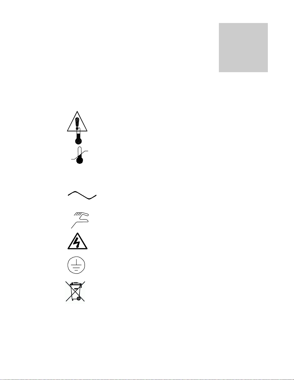
Your incubator is provided with a display of graphic symbols on the control panel which
are designed to help identify the use and function of the adjustable components.
1. Indicates that you should consult your manual for further
description and discussion of a control or user item.
2. Indicates “Temperature”
3. Indicates “Overtemperature”
4. C Indicates “Degrees Centigrade”
5. Indicates “AC Power”
6. Indicates “Manual Adjustment”
7. Indicates “Potential Shock Hazard” behind partition
8. Indicates “Earth Ground”
9. Indicates “Unit should be recycled” (Not disposed of in
land-fill)
Page 6
6
20.0
20.0
EZ1
EZ2
1 2 3
C
ACTUAL PROCESS
TEMPERATURE DISPLAY
PROCESS SETPOINT
DISPLAY
INDICATES OUTPUT 1 ACTIVE
HEATING ELEMENT ON
INDICATES OUTPUT 2
COOLING ACTIVE
INDICATES OUTPUT 3
ACTIVE LIGHTS ON
RAMPING SYMBOL
INDICATES PROGRAM
RUNNING WHEN ACTIVE
ADVANCE KEY
ALLOWS TO SCROLL
THROUGH PARAMETER LIST
DOWN ARROW KEY
ALLOWS TO LOWER SETPOINT
OR CHANGE PARAMETERS
UP ARROW KEY
ALLOWS TO RAISE SETPOINT
OR CHANGE PARAMETERS
INFINITE KEY
ALLOWS TO BACK UP
ONE LEVEL OR RETURN
TO HOME PAGE
EASY ZONE KEY 1
STARTS AND STOPS
PROGRAM
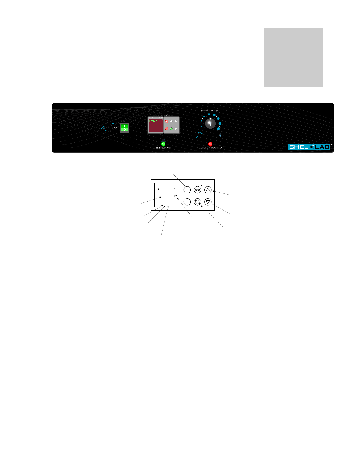
CONTROLLER KEYS AND DISPLAYS
Section
CONTROLS OVERVIEW
4.1 Power Switch: The main power I/O (on/off) switch controls all power to the unit and must be in the I/ON
position before any systems are operational.
4.2 Main Temperature Control: The Main Temperature Control is a Watlow P.I.D. (Proportional Integral
Derivative) dual output control. We strongly recommend that all operators read the included Watlow manual
to become familiar with the control. This unit is specifically designed for drosophila applications and the
actual chamber temperature will fluctuate above and below setpoint. This is normal.
4.3 HEATING Light: This pilot lamp is ON when the unit is heating up to set point and is blinking when
controlling temperature at set point.
4.4 Overtemperature Thermostat: This controller is marked SET OVERTEMPERATURE and is equipped with
an adjustment knob and a graduated dial from 0 to 10. Completely independent of the Main Temperature
Controller, the Overtemperature Thermostat guards against any failure of the Main Temperature Controller
which would allow temperature to rise past set point. If temperature rises to the Overtemperature set point,
the Overtemperature Thermostat takes control of the heating element and allows continued use of the
incubator until the problem can be resolved, or service can be arranged. It is not recommended that the unit
be allowed to operate for an extended period of time using only the Thermostat as temperature uniformity
will suffer.
4.5 OVER TEMP Light: This pilot light comes on when the Overtemperature Thermostat has been activated.
Under normal operating conditions this light should never come on.
4.6 Low Limit Thermostat: Located on the lower right rear of the unit, the Low Limit Thermostat keeps the unit
4.7 Defrost Switch: Used to defrost the unit if frost should form. It is an ON/OFF switch located on the top
4.8 Fuse: Located on the back, bottom near the cord inlet. adjacent t the defrost switch in place of the circuit
from freezing. It is factory set to activate at 1 and disengage at 3C and should not be adjusted.
right, rear of the unit.
breaker, the fuse offers protection against power source variations. Protection is in addition to the automatic
high temperature limit designed into the heating element. If the fuse is blown, the unit will shut down and the
cause should be determined and corrected before replacing the fuse.
Page 7

7
OPERATION
Section
The refrigeration system, heater, and air circulating fan are used in conjunction with the temperature control circuit to
achieve sensitive temperature control. The thermostat sensor located in the air stream senses any temperature
deviation from the control point, and heat is provided to maintain desired temperature. The circulating fan provides
even air distribution throughout the chamber and assures temperature uniformity.
The factory PID settings of the control will cycle the compressor on and off at regular, temperature controlled
intervals. This cycling will cause the temperature to fluctuate above and below setpoint and is perfectly normal. This
setting is highly recommended for Drosophila applications; however it can be changed for other applications. Note
that a factory set Low-Limit Thermostat will shut off the compressor when temperatures reach 1C.
5.1 The power supply must match the unit’s requirements listed on the data plate located on the side of the
incubator.
5.2 Plug the service cord into the power supply and turn the Power Switch to the ON position. Turn the
Overtemperature Thermostat to its maximum position, clockwise using a coin or flat edged tool.
5.3 Place a certified reference thermometer (not supplied) in the center of the chamber. Be certain the
thermostat is not touching any shelving or chamber walls. Taping the thermometer to a petri dish raises it
off the shelf and keeps the scale in view. Placing the reference thermometer in the chamber at this stage of
operation will allow for calibrating the control with out the loss of processing time.
5.4 Loading Procedure: Adequate spacing should be allowed between items whenever possible. Proper
spacing will allow maximum air circulation, which is necessary for temperature uniformity.
5.5 Set Main Temperature: The main temperature control has two displays. The upper displays the actual
temperature of the unit and the lower is the set point. To change the set point, push the up or down arrow
until the desired value is reached. Allow at least 24 hours for temperature to stabilize. It is highly
recommended that operators read the included Watlow manual and refer to it for for advanced programming
applications. As mentioned earlier, the PID settings from the factory will cycle the compressor on and off at
regular intervals. This is done to prevent damage to the incubator during Drosophila applications.
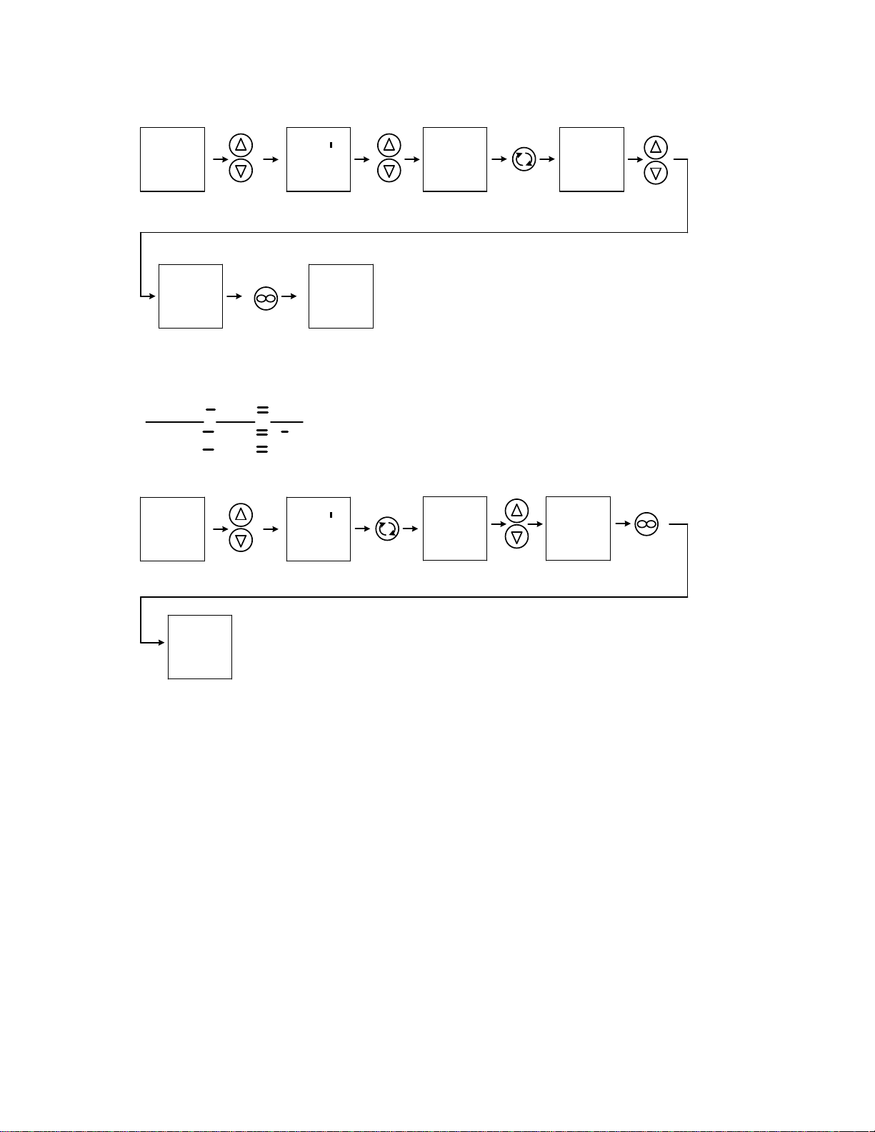
5.6 Calibrating Main Temperature Control: As mentioned previous the main control is set up to cycle the
compressor on and off causing the temperature to fluctuate. To calibrate temperature the incubator must run
at a stable temperature. To make the incubator to run at a stable temperature the PID values must be
changed in the Watlow control. Follow the instructions below to change the PID values to make the
incubator to stabilize and calibrate the temperature. Before starting place a reference thermometer on the
middle shelf like it was explained previously.
Page 8
8
PRESS AND
HOLD BOTH UP
AND DOWN
ARROWS FOR
3 SECONDS
OR UNTIL
NEXT SCREEN
20.0
20.0
OPer
A
USE UP
OR DOWN
ARROWS
TO SELECT
NEXT SCREEN
DISPLAY
OPer
LooP
PUSH
ADVANCE KEY
REPEATEDLY
UNTIL NEXT
SCREEN
DISPLAY
APPEARS
0.2
db
USE UP
OR DOWN
ARROWS
TO CHANGE
PARAMETER
O.2 TO -5.0
-5.0
db
PRESS INFINTE
KEY REPEATEDLY
TO RETURN
TO HOME
PAGE
20.0
20.0
Changing the parameter from 0.2 to -5.0 allows the compressor to stop cycling on and off and run continuously so the incubator will run stable at set point.
Allow several hours for the incubator to stabilize before calibrating. After incubator has stabilized take a reading from the reference thermometer and
subtract it from the process display. This value can be negative or positive depending on the reading of the reference thermometer. This value is also
called the offset value. See examples on determining offset value below.
PRESS AND
HOLD BOTH UP
AND DOWN
ARROWS FOR
3 SECONDS
OR UNTIL
NEXT SCREEN
20.0
20.0
OPer
A
PUSH
ADVANCE KEY
REPEATEDLY
UNTIL NEXT
SCREEN
DISPLAY
APPEARS
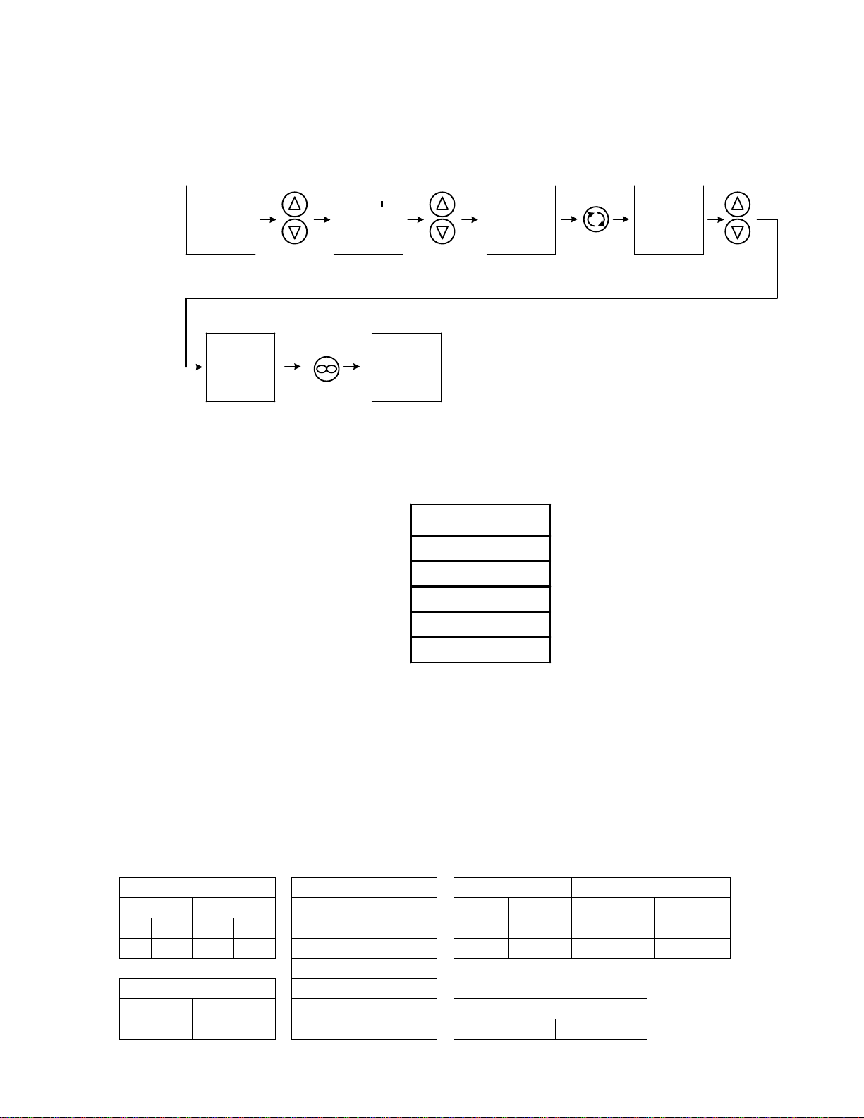
CAL
VALUE #
REFERENCE
THERMOMETER
READING
PROCESS
DISPLAY
READING
OFFSET
VALUE
20
20
18
22
2
2
To enter the offset value into the control follow the instruction below.
USE UP
OR DOWN
ARROWS
TO ENTER
THE OFFSET
VALUE
CAL
VALUE #
PRESS INFINTE
KEY REPEATEDLY
TO RETURN
TO HOME
PAGE
20.0
20.0
After the offset value has been entered allow sufficient time for incubator to stabilize and recheck reference
5.7 Set Overtemperture Thermostat: As mentioned in Step 5.2, the Overtemperature Thermostat should be
5.8 Low Temperature Control: This control is factory set and should NOT be adjusted. It is pre-set at 1C and
5.9 High Temperature Cut Off: This is a non-settable Thermo Disc that will turn the element off 50˚C to
5.10 Accessory Outlet: There is an electrical outlet inside the chamber for use with equipment not exceeding
thermometer and process display to make sure they match. If there is a unacceptable difference between
the two renter the new offset value again using the same procedure above. After calibration has been
achieved reset the C.hy parameter back to 0.2 using the same procedure above.
turned up to the maximum. Also, it is mentioned previously, the Main Control will cycle the compression on
and off causing the temperature to fluctuate up and down across setpoint. To set Overtemperature
Thermostat, turn the Key Knob counter-clockwise when the Main Temperature is at its high point swing just
until the Overtemperature Light activates. Then, turn it clockwise about 1/16 of an inch or until light goes off.
is an added feature that keeps samples from freezing.
prevent temperature runaway that could cause permanent damage to the interior of the unit.
one (1) amp. Note that equipment in the chamber may provide additional heat that could affect the
temperature range of the incubator. It is recommended that testing be done with the incubator and any
additional equipment to insure that the desired operating conditions can be met.
CAUTION: When operating at normal conditions, this incubator is capable of damaging certain accessory
equipment. Make certain that accessory equipment is capable of operating under the conditions you intend
to run your incubator.
Page 9

9
5.11 Exterior Heat: Under normal operating conditions the unit will generate enough heat to be felt by the hand
20.0
20.0
USE UP OR
DOWN ARROWS
TO SELECT HOUR OF
DAY IN TOP
DISPLAY
hoU1
HOUR OF DAY
Mi1
ENTER REAL TIME
IN HOUR OF DAY
MINUTE OF HOUR
ENTER REAL TIME
IN MINUTE OF HOUR
TO SELECT MINUTE
OF HOUR IN TOP
DISPLAY
hoU2
HOUR OF DAY
hoU1
Mi1
TO SELECT
HOUR OF DAY IN TOP
DISPLAY
ENTER DAY CYCLE
START TIME IN
HOUR OF DAY
hoU2
Mi2
Mi2
TO SELECT HOUR
OF DAY IN TOP
DISPLAY
MINUTE OF HOUR
ENTER DAY CYCLE
START TIME IN
MINUTE OF HOUR
t.SP3
DAY CYCLE SET
POINT VALUE
TO SELECT DAY
CYCLE SET POINT
IN TOP DISPLAY
t.SP3
ENTER DAY CYCLE
SET POINT
hoU4
HOUR OF DAY
TO SELECT MINUTE
OF HOUR IN TOP
DISPLAY
hoU4
ENTER NIGHT
CYCLE START TIME
IN HOUR OF DAY
Mi4
MINUTE OF HOUR
TO SELECT MINUTE
OF HOUR IN TOP
DISPLAY
Mi4
ENTER NIGHT
CYCLE START TIME
IN MINUTE OF HOUR
t.SP5
NIGHT CYCLE
SET
POINT VALUE
TO SELECT NIGHT
CYCLE SET POINT
IN TOP DISPLAY
t.SP5
ENTER NIGHT
CYCLE
SET POINT
20.0
20.0
EZ1
20.0
20.0
PROGRAMING THE DAY AND NIGHT CYCLE
PROGRAMING THE DAY AND NIGHT CYCLES ARE DONE IN JUST 8 EASY STEPS. THE FIRST TWO STEPS ARE ENTERING THE REAL TIME IN
HOURS AND MINUTES. THE NEXT THREE STEPS ARE ENTERING THE DAY CYCLE START TIME IN HOURS AND MINUTES AND THE SET POINT
AT WHICH THE DAY CYCLE WILL RUN. THE LAST THREE STEPS ARE ENTERING THE NIGHT CYCLE START TIME IN HOURS AND MINUTES
AND THE SET POINT WHICH THE NIGHT CYCLE WILL RUN. BELOW ARE INSTRUCTIONS ON HOW TO SCROLL THROUGH THE 8 STEPS AND
HOW TO CHANGE THE TIMES AND SET POINTS FOR THE REAL TIME, DAY CYCLE, AND NIGHT CYCLE.
PUSH
ONCE
PUSH
ONCE
USE UP OR
DOWN ARROWS
PUSH
ONCE
USE UP OR
DOWN ARROWS
PUSH
ONCE
USE UP OR
DOWN ARROWS
PUSH
ONCE
USE UP OR
DOWN ARROWS
PUSH
ONCE
USE UP OR
DOWN ARROWS
PUSH
ONCE
USE UP OR
DOWN ARROWS
USE UP OR
DOWN ARROWS
PUSH
ONCE
TO START
DAY/NIGHT
CYCLE
PROGRAM
PUSH
ONCE
PUSH
ONCE
TO RETURN
TO HOME
PAGE
HOME PAGE IS WHERE THE
CONTROL IS IN NORMAL CONTROL
MODE MEANING UPPER DISPLAY
IS PROCESS AND LOWER DISPLAY
IS SET POINT. TO START THE DAY
AND NIGHT CYCLE PROGRAM
PUSH THE EZ1 BUTTON ONCE.
PROGRAM IS
RUNNING WHEN
THE RAMP
SYMBOL IS
ILLUMINATED ON
THE RIGHT HAND
SIDE OF THE
DISPLAY
WHEN STARTING THE DAY AND NIGHT CYCLE IT WILL ALWAYS WAIT FOR THE DAY CYCLE FIRST. IF THE DAY TIME ENTERED IS EARLIER
THAN THE PROGRAM START TIME ( THE TIME YOU PUSH THE EZ1 BUTTON) THE PROGRAM WILL WAIT TILL THE NEXT DAY TO START.
Hou1 = REAL TIME IN HOURS OF DAY
Mi1 = REAL TIME IN MINUTES OF DAY
Hou2 = DAY CYCLE START TIME IN HOURS OF DAY
Mi2 = DAY CYCLE START TIME IN MINUTES OF THE HOUR
t
.SP3 = DAY CYCLE SET POINT VALUE
Hou4 = NIGHT CYCLE START TIME IN HOURS OF THE DAY
Mi4 = NIGHT CYCLE START TIME IN MINUTES OF THE HOUR
.SP5 = NIGHT CYCLE SET POINT VALUE
t
when touching the sides of the unit. This is normal and does not indicate improper performance.
5.12 Programming Controller for Light Operation:
Page 10
10
20.0
20.0
PRESS AND
HOLD BOTH UP
AND DOWN
ARROWS FOR
3 SECONDS
OR UNTIL
NEXT SCREEN
OPer
A
USE UP
OR DOWN
ARROWS
TO SELECT
NEXT SCREEN
DISPLAY
OPer
P.StA
PUSH
ADVANCE KEY
REPEATEDLY
UNTIL NEXT
SCREEN
DISPLAY
APPEARS
oFF
Ent 1
USE UP
OR DOWN
ARROWS
TO SELECT
on IN TOP
DISPLAY
on
Ent 1
PRESS INFINTE
KEY REPEATEDLY
TO RETURN
TO HOME
PAGE
20.0
20.0
PID SETTINGS (from factory)
P.I.D.
h.Pb 12.0
c.hy
0.2
ti
180
td
50
db
0.2
=
=
=
=
=
diO SET
LOOP SET 1
FUN 1
FUN 2
diO 5
diO 6
n.Ag
pid
LEV
HIGH
LEV
HIGH
dir
otPt
dir
otPt Ca.g
ON Off
fn
P.Str
Fn
NONE
FN
OFF
FN
OFF h.Pb
12.0
Fi I Fi 0
c.hy
0.2
A1 SET
t1
180
SEN
RO.1H
td
50
gLbL SET
Rtl
2 db
02 C.F
C
5.13 Operating Lights Manually Without Running Program: To turn lights on without running a program
ENT1 (event output 1) must be turned on. Follow instruction below on how to turn the output on.
To turn the lights off follow the same procedure but, turn ENT1 to off.
The PID values or stored in the loop menu under operation page. These parameters control how the unit
will control at set point. The incubator is setup from the factory to cycle the compressor on and off to keep
the evaporator from freezing up to eliminate damage to the coil from off gassing from Fruit Fly growth. Due
to the cycling of the compressor the temperature will fluctuate up and down above and below set point. To
run the incubator at a stable temperature, change the parameter c.hy to -5.0. This will make the compressor
to run continuously and should make the incubator run stable at set point. All other parameters are control
sensitive and should not be changed. To enter the loop menu follow the instruction under calibration
procedure.
5.14 Set Up Parameters: The setup parameters are parameters that configure the control on how it functions
and should not be changed. Below is the list of parameters that is sent from the factory for reference. They
should never be changed unless there is a complete understanding of what they do and how they will affect
control functions. For better understanding on what these functions do refer to the Watlow manual on the
Watlow disk.
Page 11

11
F.L
0.5
t.tun
no AC.LF
60
lEr
OFF
A.tsp
90 Rtyp
t1
dEL
0.0
t.agr
Crit P.tyt
StPt
i.ca
0.0
P.dL
5.0 gSE
OFF
A.in
ambient
U.FA
USEr SiA
5
i.Er
none
FAIL
USEr Sib 6
L.dE
No Pot1
9999
rtC
rP
OFF C.Led
both
Hour
Current
time hours
L.SP
0.0 ZonE
on
Min
Current
time
minutes
h.SP
45 ChAn
on
dow
Day of
week
C.SP
20.0 d.Prs
1
l.dS
AMPIENT
d.t1
0
CoM SET
SP.lo
100 USr.S
none
Ads
1
SP.hi
100 USr.r
none
map
1
0.SP
0.00
NUS
YES
C.M
Auto
OtPt SEt
OtPt 1 OtPt 2 OtPt
3
Fn
heat
Fn
COOL
ENT A
FN
0.Ct
Vtb
40.0
O.Tb
0.Lo 0 0%
o.lo
0.hI
100
100%
o.hi
ALM SEt
ALM 1
ALM 2
ALM 3
ALM 4
A.ty OFF
A.ty OFF
A.ty OFF
A.ty FN
Page 12

MAINTENANCE
Section
The design of the chamber is such that periodic maintenance is kept to a minimum. NO lubrication or adjustments of
components is needed. If the incubator is used frequently at temperatures below ambient room temperature or in any
manner that increases moisture build-up within the chamber, a frequent defrosting schedule is recommended.
6.1 Defrosting: Frost can appear inside the unit due to moisture accumulating and condensing on the coldest
surface. The unit should be defrosted and cleaned on a regular basis. The unit can be defrosted either
manually or automatically. The water drains from the chamber into a evaporate pan. Make sure to
completely dry out the interior and evaporate tray in the bottom of the body when defrosting is complete.
A. Manual Defrost: Turn the unit off, open the door and allow the frost to melt. Then clean the
chamber following the directions in 6.2.
B. Automatic Defrost: The automatic defrost switch is located on the back of the unit in the top right
corner. It is an ON/OFF switch. In the ON position, the frost sensor is activated once every twelve
(12) hours. If the sensor detects frost, the compressor is shut down until the frost has melted, and the
compressor is reactivated. The amount of time the compressor is shut down is roughly one-half hour.
During this time, the temperature in the chamber will spike and the Main temperature Controller will
cycle off, shutting down the heating element. When the compressor is reactivated, the temperature
will stabilize at set point.
6.2 Cleaning: Clean the incubator with a mild soap and water solution, rinse clean with water and wipe dry with
a soft cloth.
6.3 Disinfecting: Disinfect the incubator on a regular basis. Remove all of the interior parts and clean
thoroughly, including all corners using a suitable disinfectant that is appropriate for your application. DO
NOT use spray cleaners that might leak through openings and cracks and get on electrical components, or
that may contain solvents that will harm the coatings. DO NOT use abrasives of any kind as they will
damage the interior. Special care should be taken when cleaning around sensing heads to prevent damage
and around the door gasket so as not to impair the positive seal.
WARNING: Never clean the unit with alcohol or flammable cleaners with the unit connected to the electrical
supply. Always disconnect the unit from the electrical service when cleaning and assure all volatile or
flammable cleaners are evaporated and dry before reattaching the unit to the power supply.
6.4 Compressor Compartment: Located at the back and bottom of the unit, the compressor compartment can
collect dust which will inhibit proper airflow. This compartment should be vacuumed out at least once every
six (6) months to ensure maximum efficiency. Note that the unit must be disconnected from the power
supply during this procedure, and removal of the wire safety screen is required if it is equipped with one.
6.5 Electrical Components: There is NO maintenance to electrical components such as Temperature
Controllers and Probes. If the incubator fails to operate properly, read the Troubleshooting guide prior to
contacting Customer Service. If service is required, access to all electrical components is available by
removing the panel cover at the top rear of the unit. Temperature Controllers are accessible from behind the
control panel. Main Temperature Probe is located on the interior chamber back. Thermostat Probe is
located in the element chamber. If the Low Limit Temperature Thermostat needs adjustment, contact the
factory for assistance.
Page 13

13
TROUBLESHOOTING and SERVICE
TEMPERATURE
Temperature too high
1/ controller set too high-see section 5.5
2/ controller failed on – call Customer Service
Temperature too low
1/ Overtemperature set too low
2/ controller set too low
3/ unit not recovered from power failure or being turned off –
incubators will need to warm up and stabilize.
4/ element failure – see if heating light is on; compare current
draw to data plate.
5/ controller failure – confirm with front panel lights that controller
is calling for heat.
6/ Overtemperature Thermostat failure – confirm with front panel
lights that thermostat is operating correctly.
Unit will not heat
1/ verify that controller is asking for heat by looking for heating
light is activated.
2/ do all controller functions work?
3/ is the Thermostat set high enough? – for diagnostics, should
be fully clockwise with the pilot light never on.
Display and reference thermometer
don’t match
1/ calibration error – see chapter 4 of Watlow Manual- calibration
offset 1
2/ temperature sensor failure – evaluate if pilot light is operating
correctly.
3/ controller failure – evaluate if pilot light is operating correctly
4/ allow at least two hours to stabilize.
5/ see if reference thermometer is certified.
Calibrated at one temperature, but
not at another
This can be a normal condition when operating temperature varies
widely. For maximum accuracy, calibration should be done as
close to the set point temperature.
REFRIGERATION
Temperature can't get up to set point
1/ if light not coming on, check control set point and
Overtemperature set point .
2/ confirm that fan is operating and airflow is not blocked.
Section
When troubleshooting, always make a visual inspection of the incubator and its control console to find
loose or disconnected wires which may be source of the trouble. In the event the incubator does not
operate properly, check the following before calling for service.
Page 14

14
Unit won't cool
1/ be sure that fan is circulating air in the chamber and over the
compressor.
2/ confirm proper sensor location and operation.
3/ look for leaks in the chamber or around the door gasket.
4/ assure ample room around the unit as described in Installation
section 2.2.
5/ compare ambient specifications to Unit specifications in section
8.0.
Ice build up in chamber
1/ Search for leak in door gasket.
2/ door being opened too often.
3/ open container inside the chamber.
4/ check tightness of seal around all chamber wire and plumbing
access to outside.
5/ turn defrost switch on, Note: defrost switch must be turned off
for best temperature uniformity; If no defrost option available, call
Customer Service.
MECHANICAL
Door not sealing
1/ Confirm that unit has not been damaged and body is not
square.
OTHER
Front panel displays are all off
Check for wire damage.
Unit or wall fuse/circuit breaker is
blown
1/ check wall power source.
2/ see what other loads are on the wall circuit.
Unit will not turn on
1/ check wall power source.
2/ check fuse/circuit breaker on unit or in wall.
Contamination in chamber
1/ see cleaning procedure in operator’s manual
2/ develop and follow Standard operating procedure for specific
application; include definition of cleaning technique and
maintenance schedule.
Service
If none of the suggestions listed above in the Troubleshooting guide have solved
the problem Customer Service should be contacted for assistance.
Call 1-800-322-4897, and have the model number, serial number and voltage
(listed on the date plate on the side of the incubator) as your service
representative will require it.
Page 15

15
PARTS LIST
Description
100-120V
Units
220-240V
Units
Blower Motor
4880564
4880564
Circuit Breaker
1100500
1100500
Convenience Outlet
6100525
6100531
Defrost Switch
7850579
7850579
High Limit Control
1750538
1750538
I/O (on/off) Switch
7850553
7850553
Low Limit Control
1750538
1750538
Temperature Controller Watlow PM
9660515
9660515
Overtemperature Thermostat
1750862
1750862
Pilot Light, Green
4650554
4650554
Pilot Light, Red
4650553
4650553
Relay Mechanical
7030536
7030536
Relay Solid State
7030533
7030533
RTD Temperature Probe
6600520
6600520
Fan Guard
2600518
2600518
Power Cord
1800529
1800541
Section
Page 16

16
UNIT SPECIFICATIONS
SRI21F (LIFLY) &
SRI21FV (LIFLY-
VIEW )
SRI21F-2 (LIFLY-2) &
SRI21FV-2 (LIFLY-
2VIEW)
Shipping Weight
340 lbs.
340 lbs.
Net Weight
246 lbs.
246 lbs.
Exterior WxDxH (in.)
Dimensions
32 x 32 x 77
32 x 32 x 77
Interior WxDxH (in.)
Dimensions
27 x 23.5 x 57
27 x 23.5 x 57
Capacity
20.3 cubic feet
20.3 cubic feet
Capacity
305 bottles
305 bottles
Temperature Range
0° TO 45°C
0° TO 45°C
Electrical
100-120V
9.5
220-240V
4.0
The equipment is rated for ingress protection IPX0.
Page 17

17
WIRING DIAGRAM
SRI21F (LIFLY) SRI21FV (LIFLY-VIEW) 100V-120V
9851583
Page 18
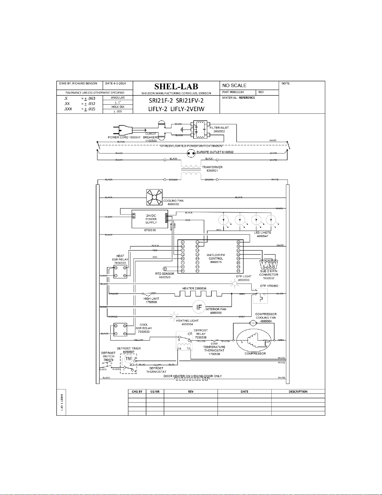
18
WIRING DIAGRAM
SRI21F-2 (LIFLY-2) SRI21FV-2 (LIFLY-2VIEW) 220-240V
9851584
 Loading...