


WATERJACKET CO2 INCUBATORS
WITH MICROPROCESSOR CONTROL
SCO2W SCO2W-2
PREVIOUSLY DESIGNATED
3503 3503-2
INSTALLATION AND OPERATION MANUAL
12/2013
4861610
Sheldon Manufacturing Inc. P.O. Box 627 Cornelius, Oregon 97113
EMAIL: tech@Shellab.com INTERNET: http://www.Shellab.com/~Shellab
1-800-322-4897 (503) 640-3000 FAX (503) 640-1366
TABLE OF CONTENTS
SECTION 1.0 |
RECEIVING AND INSPECTION |
SECTION 2.0 |
GRAPHIC SYMBOLS |
SECTION 3.0 |
INSTALLATION |
SECTION 4.0 |
CONTROL PANEL OVERVIEW |
SECTION 5.0 |
OPERATION |
SECTION 6.0 |
FYRITE CO CHECKING |
SECTION 7.0 |
HEPA C02 FILTER |
SECTION 8.0 |
MAINTENANCE |
SECTION 9.0 |
TROUBLESHOOTING |
SECTION 10.0 |
PARTS LIST |
|
UNIT SPECIFICATIONS |
|
SCHEMATICS |
These units are CO Water Jacketed incubators for professional, industrial or educational use where the preparation or testing of materials is done at approximately atmospheric pressure and no flammable, volatile or combustible materials are being heated. These units are not intended for hazardous or household locations or use.
2

1Section
RECEIVING AND INSPECTION
IMPORTANT: READ THIS INSTRUCTION MANUAL IMMEDIATELY!
Your satisfaction and safety require a complete understanding of this unit, including its proper function and operational characteristics. Be sure operators are given adequate training before attempting to put the unit in service. NOTE: This equipment must be used only for its intended application; any alterations or modifications will void your warranty.
1.1Inspection: The carrier, when accepting shipment, also accepts responsibility for safe delivery and is liable for loss or damage claims. On delivery, inspect for visible exterior damage, note and describe on the freight bill any damage found and enter your claim on the form supplied by the carrier.
1.2Inspect for concealed loss or damage on the unit itself, both interior and exterior. If any, the carrier will arrange for official inspection to substantiate your claim. Save the shipping crate until you are sure the unit has been delivered in good condition.
1.3Return Shipment: If for any reason you must return the unit, contact your customer service representative for authorization and supply nameplate data. For information on where to contact Customer Service please see the manual cover.
1.4Accessories: Make sure that all of the equipment indicated on the packing slip is included with the unit. Carefully check all packaging before discarding. Each chamber comes equipped with 3 shelves, 4 shelf standards, 1 humidity pan and a power cord. All units are shipped with 4 leveling feet and supply hose kit.
3
2Section
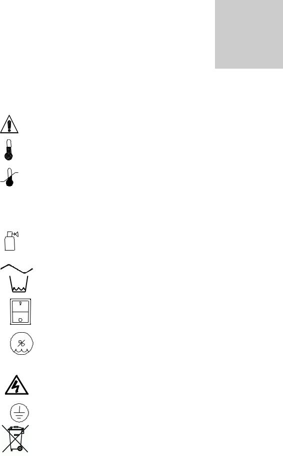
GRAPHIC SYMBOLS
Your incubator has been provided with a display of graphic symbols which is designed to help in identifying the use and function of the available user adjustable components.
2.1 |
|
Indicates that you should consult your manual for further description |
|
|
or discussion of a control or user item. |
2.2 |
|
Indicates "Temperature". |
2.3 |
|
Indicates "Over-temperature safety". |
2.4 |
C |
Indicates "Degrees Centigrade". |
2.5CO2 Indicates "Carbon Dioxide".
2.6 |
Indicates "Gas" (CO2 for this unit). |
2.7 |
Indicates "AC Power ". |
2.8 |
Indicates "Water Jacket Low". |
2.9 |
Indicates "ON/I" and "OFF/O". |
2.10 |
Indicates "Relative Humidity". |
2.11%RH Indicates "Percent Relative Humidity".
2.12 |
Indicates "Potential Shock Hazard" behind this protective partition. |
2.13 |
Indicates "Protective Earth Ground". |
2.14 |
Indicates “Unit should be recycled” (Not disposed of in land-fill) |
4

3Section
INSTALLATION
Local city, county, or other ordinances may govern the use of this equipment. If you have any questions about local requirements, please contact the appropriate local agency. Installation may be performed by the end user.
Under normal circumstances this unit is intended for use indoors, at room temperatures between 5 and 40 C, at no greater than 80% Relative Humidity (at 25 ) and with a supply voltage that does not vary by more than 10%. The unit’s technical and environmental specifications includes: altitude not exceeding 2000 m operating and Pollution Degree of 2. Customer service should be contacted for operating conditions outside of these limits.
CAUTION: Make sure that the incubator is located in its intended position and level before filling the water jacket. Directions for filling the jacket are in Section 5.2.
3.1Power Source: The power supply must be properly grounded (earthed) and correctly sized to match the unit nameplate rating. The supply voltage must match the nameplate voltage within +/- 10%. These units are intended for 50/60 Hz application. If supplied with a detachable cord set, plug the female end into the inlet on the unit and the male plug into the supply. Assure that units requiring a fuse have a fuse installed. This fuse may be at the inlet or a part of the cord set male plug.
3.2Location: When selecting a site for the unit, consider conditions which may affect performance, such as heat from steam radiators, ovens, autoclaves, etc. Avoid direct sun, fast-moving air currents, heating/cooling ducts, and high-traffic areas. To ensure air circulation around the unit, allow a minimum of 10cm of clearance between the incubator and surrounding walls, or obstructions to free air flow.
3.3Lifting / Handling: These units are heavy and care should be taken to use appropriate lifting devices that are sufficiently rated for these loads. Units should only be lifted from their bottom surfaces. Doors, handles and knobs are not adequate for lifting or stabilization. The unit should be completely restrained from tipping during lifting or transport. All moving parts, such as shelves and trays should be removed and doors need to be positively locked in the closed position during transfer to prevent shifting and damage.
3.4Leveling: The unit must sit level and solidly. Leveling feet are supplied and must be installed in the four holes in the bottom corners of the unit. With the feet installed and the unit standing upright, each foot can be raised by turning it in a counterclockwise direction. Adjust the foot at each corner until the unit stands level and solid without rocking. If the unit must be moved, drain all of the water from the unit and turn the leveling feet in (clockwise) all the way to prevent damage while moving.
3.5Cleaning: The unit chamber should be cleaned and disinfected prior to use. Individual operating conditions and appropriate protocol will determine the correct procedure for decontamination. A typical decontamination procedure that is adequate for many situations has been described below. As well, certain steps are listed that will help reduce the likelihood of contamination and the necessity of decontamination. Whatever process is appropriate, it needs to be done on a regularly scheduled basis. Depending on usage and protocol, this may be monthly, quarterly or otherwise. Regardless of the decontamination procedure used, certain precautions will need to be taken:
A.Always disconnect the unit from the electrical service when cleaning.
Assure all volatile or flammable cleaners are evaporated and dry before reconnecting the unit to the power supply.
5
B.Special care should be taken when cleaning around sensing heads to prevent damage.
C.If you use chlorine-based bleaches or abrasive cleaners this will modify the stainless steel interior finish. DO NOT USE hard tools such as metal wire brushes or steel wool. Use non-abrasive cleaners and soft tools such as plastic brushes.
TYPICAL DECONTAMINATION PROCEDURE
1.Remove the humidity pan every week and autoclave, or wash with soap and water then disinfect with 70% alcohol solution. Replace in the incubator with fresh, DISTILLED water.
2.Flush the sample port tubing with 70% alcohol solution. Replace any lines that have a green color.
3.Remove the door gaskets, clean and disinfect. Clean and disinfect all mounting grooves for the door gaskets.
4.Remove all shelves, shelf supports, shelf standards and shields. Autoclave, or wash and disinfect as described in item 1.
5.Wash and disinfect all interior surfaces.
6.Give special attention to cleaning and disinfecting all access ports, air bleeds, shaft holes, electrical pass-through and any other passages into the chamber.
7.Replace all air and CO2 filters every six months or when noticeably dirty on the upstream side. CO2 filters are located in the shadow box just behind the GAS IN fitting and in line with the CO2 tubing kit. Units with flow meters require operatorsupplied air pumps. These pumps should be checked for proper air filtering.
OPERATION FOR MINIMIZING CONTAMINATION
1.Keep the outside of the incubator, including the air in the laboratory, as clean as possible. This is particularly important for units placed directly on the floor. Do not place
incubators near doors, air vents or other areas of high air movement or traffic.
2.The floor around the unit needs to be clean. Units that are placed on the floor should be mounted higher – typically on a caster platform – for ease of moving the unit during cleaning and access to the back of the unit.
3.Minimize the number of times access is made to the chamber during normal operation.
4.Do not depend on the use of antibiotics to maintain uncontaminated conditions, as this is an inadequate technique for sterilization. Preferably use aseptic techniques as described above for maintaining sterile conditions in the incubator.
6

3.6Shelves and Interior Parts: Shelving, shelf supports and a humidity pan are supplied with each unit. See Figure 1, for proper placement of these accessories.
Figure 1
3.7Download USB Software: Go to www.shellab.com website home page and scroll down towards the bottom of the page. Click on this section:
To use your SHEL LAB CO2 Incubator USB features, you need to download the software by clicking on the image below.
Open the Excel Spreadsheet SLDL0092 and download information.
7

4Section
CONTROL PANEL OVERVIEW (See Figure 2)
All controls are located on the front panel. Units with a detachable cord have a fused inlet located at the top rear of the control panel. This inlet has a recessed male plug, fuse and an EMI filtering system designed to filter out electrical interference. This inlet also prevents any internally generated interference from feeding out to the power grid.
4.1Power Switch: The I/O (ON/OFF) switch controls all of the power for the incubator and must be in the I/ON position before any systems are operational. Both temperature and CO2 displays will illuminate when the power switch is in the ON position.
4.2Water Low Light: This pilot lamp is on whenever the internal water jacket float switch has been tripped to the closed position. When the water drops low enough the float switch closes the circuit turning on the indicator light.
4.3Over Temperature Light: This pilot lamp is on whenever the Over Temperature Safety thermostat has been activated and taken control of the element. During normal operating conditions this indicator should never be on.
4.4Main Temperature Control: This controller is marked in C and indicates the actual temperature within the chamber to .1 C. The UP/DOWN buttons are used for inputing the set point, calibrating the display, and muting or unmuting the audible alarm. The HIGH and LOW alarm indicators will light whenever there is an alarm condition associated with the temperature within the chamber. The MUTE indicator will light whenever the audible alarm has been deactivated. Some alarm conditions have a delay programmed in.
4.5Heating Light: This pilot lamp is on whenever the Temperature Controller is activating the heating element.
4.6 C02 Control On Water Jacket Incubators: The control sets the rate and the limit of injection of CO2 into the incubator based on input value and some variables. The input value is set by the operator. This is set at 5% CO2 in production. The variables are the amount of humidity in the chamber, and the amount of time the control has been trying to inject CO2.
At start-up, the incubator must be warmed up to operating temperature. This is set in production at 37°C. During warm up, the water tray for humidity should be filled and placed inside. This allows the humidity to reach 95% before CO2 is injected.
The CO2 should be turned OFF during warm up. Failure to do so will cause the control overshoot the set value input by the operator, the injection value can be reset by setting the CO2 levels down until the display shows “CL”. Resetting the desired value resets the injection rate and limit values to that which was input by the operator. The unit would be then be reset to the selected temperature on main and the door and the CO2 set to the desired level.
4.7Injection Light: This pilot lamp is on whenever the CO2 controller is injecting CO2 into the chamber.
4.8Over Temperature Safety Control (OTP): Located front left of the control panel, this is a hydraulic thermostat that is wired between the Main Temperature Controller and the heating element and functions as an override control. If at any time the Main Temperature Control fails in the ON position and the temperature in the chamber rises above its set point, the OTP is activated and maintains temperature at its own set point. Note that the HEATING indicator will continue to function under the control of the OTP.
8
 Loading...