

Page 1

1-800-322-4897
(503) 640-3000
FAX (503) 640-1366
LOW TEMPERATURE
DIURNAL ILLUMINATION
INCUBATOR
SRI21D SRI21D-2
Previously designated as:
LI15 LI15-2
INSTALLATION AND OPERATION MANUAL
Revised 11/2013
4861575
Sheldon Manufacturing Inc. P.O. Box 627 Cornelius, Oregon 97113
EMAIL: tech@Shellab.com INTERNET: http://www.Shellab.com/~Shellab
Page 2

2
TABLE OF CONTENTS
SECTION 1.0 RECEIVING AND INSPECTION
SECTION 2.0 INSTALLATION
SECTION 3.0 GRAPHIC SYMBOLS
SECTION 4.0 CONTROL PANEL OVERVIEW
SECTION 5.0 OPERATION
SECTION 6.0 MAINTENANCE
SECTION 7.0 TROUBLESHOOTING
SECTION 8.0 PARTS LIST
UNIT SPECIFICATIONS
WIRE DIAGRAMS
These units are general purpose Biochemical Oxygen Demand (BOD) incubators for
professional, industrial or educational use where the preparation or testing of materials is done
at approximately atmospheric pressure and no flammable, volatile or combustible materials are
being heated. These units are not intended for hazardous or household locations or use.
Page 3

3
RECEIVING AND INSPECTION
Section
Your satisfaction and safety require a complete understanding of this unit. Read the instructions
thoroughly and be sure operators are given adequate training before attempting to put the unit into
service. This equipment must be used only for its intended application; any alterations or
modifications will void your warranty.
1.1 Inspection: The carrier, when accepting shipment, also accepts responsibility for safe
delivery and is liable for loss or damage. On delivery, inspect for visible exterior damage,
note and describe on the freight bill any damage found, and enter your claim on the form
supplied by the carrier.
1.2 Inspect for concealed loss or damage on the unit itself, both interior and exterior. If
necessary, the carrier will arrange for official inspection to substantiate your claim.
1.3 Return Shipment: Save the shipping crate until you are sure all is well. If for any reason
you must return the unit, first contact your customer representative for authorization. Supply
nameplate data, including model number and serial number. Please see the manual cover
for information on where to contact Customer Service.
1.4 Accessories: Verify that your accessory package is complete. Each unit is equipped with
a key and four (4) shelves.
WARNING: Never use this unit for the growth, cultivation, incubation or storage of fruit flies
(drosophila melanogaster). This unit is not designed for use with fruit flies. Improper use of
this unit, including use with fruit flies, will void any warranty. Other units are specifically
manufactured for fruit fly application, and you should consult your dealer or the manufacturer
in order to identify another model suitable for your application.
Page 4

4
INSTALLATION
Section
Local city, county, or other ordinances may govern the use of this equipment. If you have any questions about local
requirements, please contact the appropriate local agency. Installation may be performed by the end user. It is
unnecessary for this unit to be installed by a technician.
Under normal circumstances this unit is intended for use indoors, at room temperatures between 18 and 28C, at no
greater than 80% Relative Humidity ( at 25C ) and with a supply voltage that does not vary by more than 10%.
Customer service should be contacted for operating conditions outside of these limits.
This unit should remain upright for 24 hours prior to operating. This will allow the oil to settle in the compressor.
2.5 Power Source: See the incubator's serial/data plate for the voltage, cycle, phase and
ampere requirements. VOLTAGE SHOULD NOT VARY MORE THAN 10% FROM THE
DATA PLATE RATING. These units are intended for 50/60 Hz application. Electrical
supply to the unit must conform to all national and local electrical codes. A separate circuit
is recommended to avoid overloading or failure of other equipment on the same circuit.
2.6 Location: When selecting a site for the incubator, consider all conditions which may
affect performance, such as extreme heat from steam radiators, stoves, ovens,
autoclaves, etc. Avoid direct sun, fast-moving air currents, heating/cooling ducts, and high
traffic areas. To ensure air circulation around the unit allow a minimum of 20cm between
incubator and any walls or partitions which might obstruct free air flow.
2.7 Lifting / Handling: These units are heavy and care should be taken to use appropriate
lifting devices that are sufficiently rated for these loads. Units should only be lifted from
their bottom surfaces. Doors, handles and knobs are not adequate for lifting or
stabilization. The unit should be completely restrained from tipping during lifting or
transport. All moving parts, such as shelves and trays should be removed and doors need
to be positively locked in the closed position during transfer to prevent shifting and
damage.
2.8 Leveling: The unit must sit level and solidly. Turn the leveling feet counterclockwise to
raise level. If the unit must be moved, turn the leveling feet in all the way to prevent
bending or damage.
2.9 Cleaning: The incubator's interior was cleaned at the factory, but not sterilizied. Remove
all interior parts, including shelves and clean thoroughly with a disinfectant that is
appropriate for your application. Regular periodic cleaning is required. Special care
should be taken when cleaning around sensing heads to prevent damage. DO NOT USE
chlorine based bleaches as this may damage the incubator interior. DO NOT USE spray
cleaners that might leak through cracks and openings and get on electrical components,
or that may contain solvents that will harm coatings.
WARNING: Never clean the unit with alcohol or flammable cleaners with the unit connected to
the electrical supply. Always disconnect the unit from the electrical service when cleaning and
assure all volatile or flammable cleaners are evaporated and dry before reattaching the unit to the
power supply.
Page 5
5
GRAPHIC SYMBOLS
Section
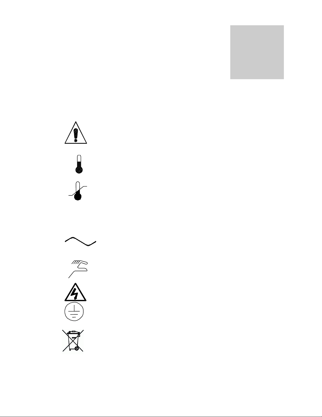
Your incubator is provided with a display of graphic symbols on the control panel which
are designed to help identify the use and function of the adjustable components.
1. Indicates that you should consult your manual for further
description and discussion of a control or user item.
2. Indicates “Temperature”
3. Indicates “Overtemperature”
4. C Indicates “Degrees Centigrade”
5. Indicates “AC Power”
6. Indicates “Manual Adjustment”
7. Indicates “Potential Shock Hazard” behind partition
8. Indicates “Earth Ground”
9. Indicates “Unit should be recycled” (Not disposed of in
land-fill)
Page 6
6
CONTROL PANEL OVERVIEW
Section
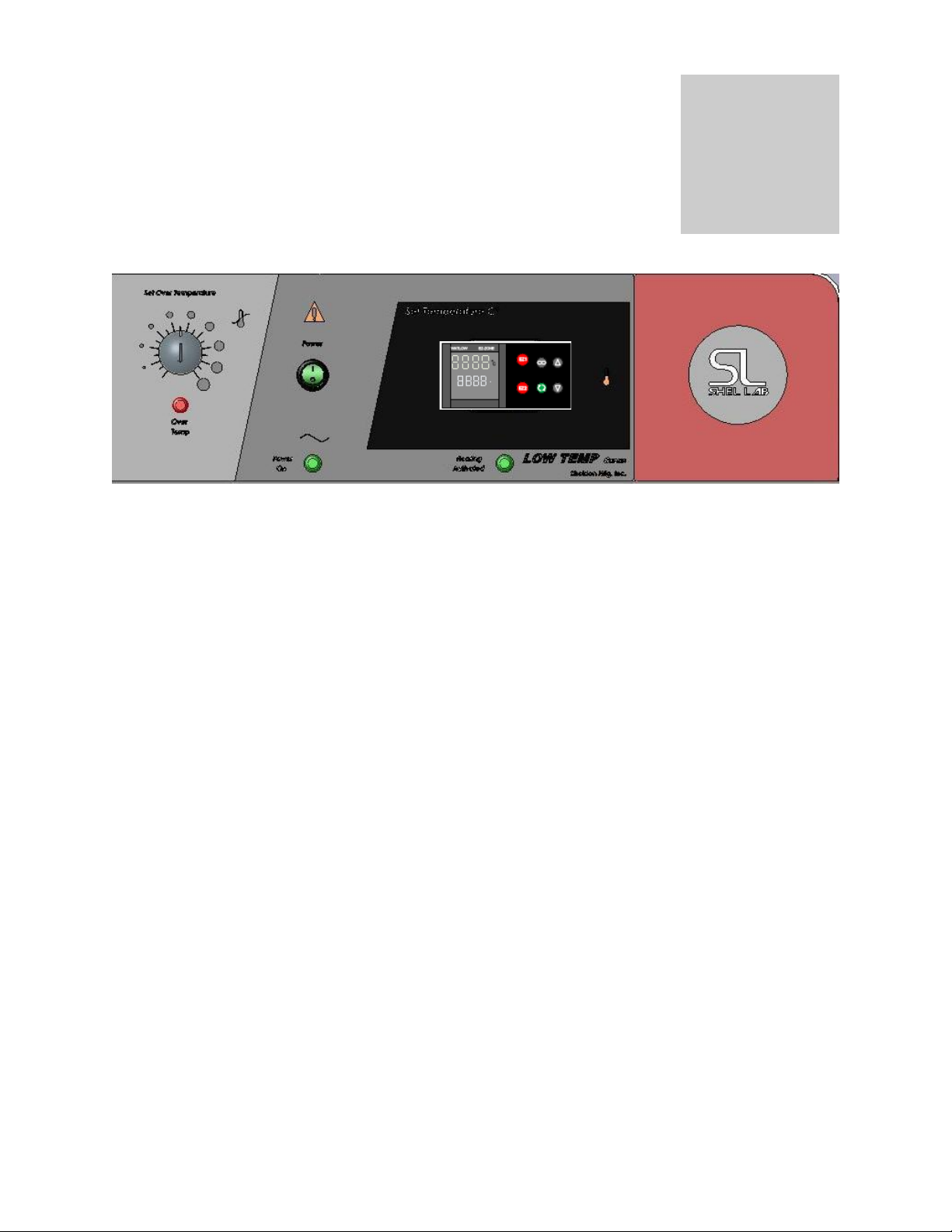
The SRI21D (LI15) comes with one control (Watlow PM) that can be set to do all light and
temperature setting functions. It has an ON/OFF Power Switch to turn the unit ON or OFF and
one Over Temperature Protection for High Temperature Limit.
4.1 Power Switch: The main power I/O (on/off) switch controls all power to the unit and must
be in the I/On position before any systems are operational.
4.2 Main Temperature Control: This control is marked SET TEMPERATURE and AM/PM
LIGHT CONTROL. It has two digital displays. Top Display reads PROCESS
TEMPERATURE and bottom display reads SET POINT TEMPERATURE. The control is a
40-Step Ramp and Soak Programmable Control with two (2) Event Outputs.
4.3 Over Temperature Thermostats: This control are marked SET OVER TEMPERATURE
4.4 HEATING Light: Marked HEATING ACTIVATED, this pilot light indicates when the Main
4.5 OVERTEMP Light: Marked OVER TEMPERATURE ACTIVATED, this pilot light indicates
4.6 Circuit Breaker: Located on the rear bottom next to the cord inlet provides protection
and are equipped with adjustment knob and graduated dial. Completely independent of the
Main Controller, the Thermostat guards against any failure which would allow temperature
to rise past the Main Controllers set point. If temperature rises to the Over Temperature set
point, this thermostat takes control of the heating element and allows continued use of the
incubator until the problem can be resolved or service can be arranged. It is not
recommended that the unit be allowed to operate for an extended period of time using only
the Over Temperature thermostat as temperature uniformity will suffer.
Controller has activated the heating elements to reach and maintain set point temperatures.
when the Over Temperature Thermostat has been activated. Under normal operating
conditions this pilot light should never come on.
against power source variations. Protection is in addition to the automatic high temperature
limit designed into the heating element. If the Circuit breaker opens, the unit will shut down
and the cause should be determined and corrected before resetting the circuit breaker.
Page 7

7
OPERATION
Section
The refrigeration system, heater, and air circulating fan are used in conjunction with the
temperature control circuit to achieve sensitive temperature control. The temperature sensor
located in the air stream senses any temperature deviation from the control point, and heat is
provided to maintain desired temperature. The circulating fan provides even air distribution
throughout the chamber and assures temperature uniformity.
Regardless of the temperature maintained, the refrigeration system operates continuously. This
constant operation minimizes component failures which are more frequently associated with a
cycling type operation. Note that a factory set Low-Limit Thermostat will shut off the compressor
when temperatures reach around 1C so samples will not freeze.
5.1 Plug incubator into electrical service corresponding to data plate rating located on the side
of the unit. Turn the power switch to the ON position and turn the Overtemperature
Thermostat to its maximum position, clockwise using a coin or flat edged tool.
5.2 Place a certified reference thermometer (not supplied) in the center of the chamber. Be
certain the thermometer is not touching any shelving or chamber walls. Taping the
thermometer to a petri dish raises it off the shelf and keeps the scale in view. Placing a
reference thermometer in the chamber at this stage of operation will allow for calibrating
the control without the loss of processing time.
5.3 Loading Procedure: Adequate spacing should be allowed between items whenever
possible. Proper spacing will allow maximum air circulation, which is necessary for
temperature uniformity.
5.4 Frost Buildup: Excessive frost buildup on the evaporator coil located on the lower rear
wall can affect temperature uniformity. Liquid containers should never be placed in the
chamber without covers. The evaporation of moisture within the chamber will only add
frost and hasten the need for defrosting. Defrosting instructions are available in
Maintenance Section 6.
Page 8
8
WATLOW PM CONTROLLER START GUIDE
20.0
20.0
EZ1
EZ2
1 2 3
C
ACTUAL PROCESS
TEMPERATURE DISPLAY
PROCESS SETPOINT
DISPLAY
OUTPUT 1 INDICATES
HEATING ELEMENT ON
OUTPUT 2 INDICARES
LIGHTS ON
OUTPUT 3 INDICATES
CALIBRATION OFFSET
ON FOR DAY CYCLE
RAMPING SYMBOL
INDICATES PROGRAM
RUNNING WHEN ACTIVE
ADVANCE KEY
ALLOWS TO SCROLL
THROUGH PARAMETER LIST
DOWN ARROW KEY
ALLOWS TO LOWER SETPOINT
OR CHANGE PARAMETERS
UP ARROW KEY
ALLOWS TO RAISE SETPOINT
OR CHANGE PARAMETERS
INFINITE KEY
ALLOWS TO BACK UP
ONE LEVEL OR RETURN
TO HOME PAGE
EASY ZONE KEY 1
STARTS AND STOPS
PROGRAM
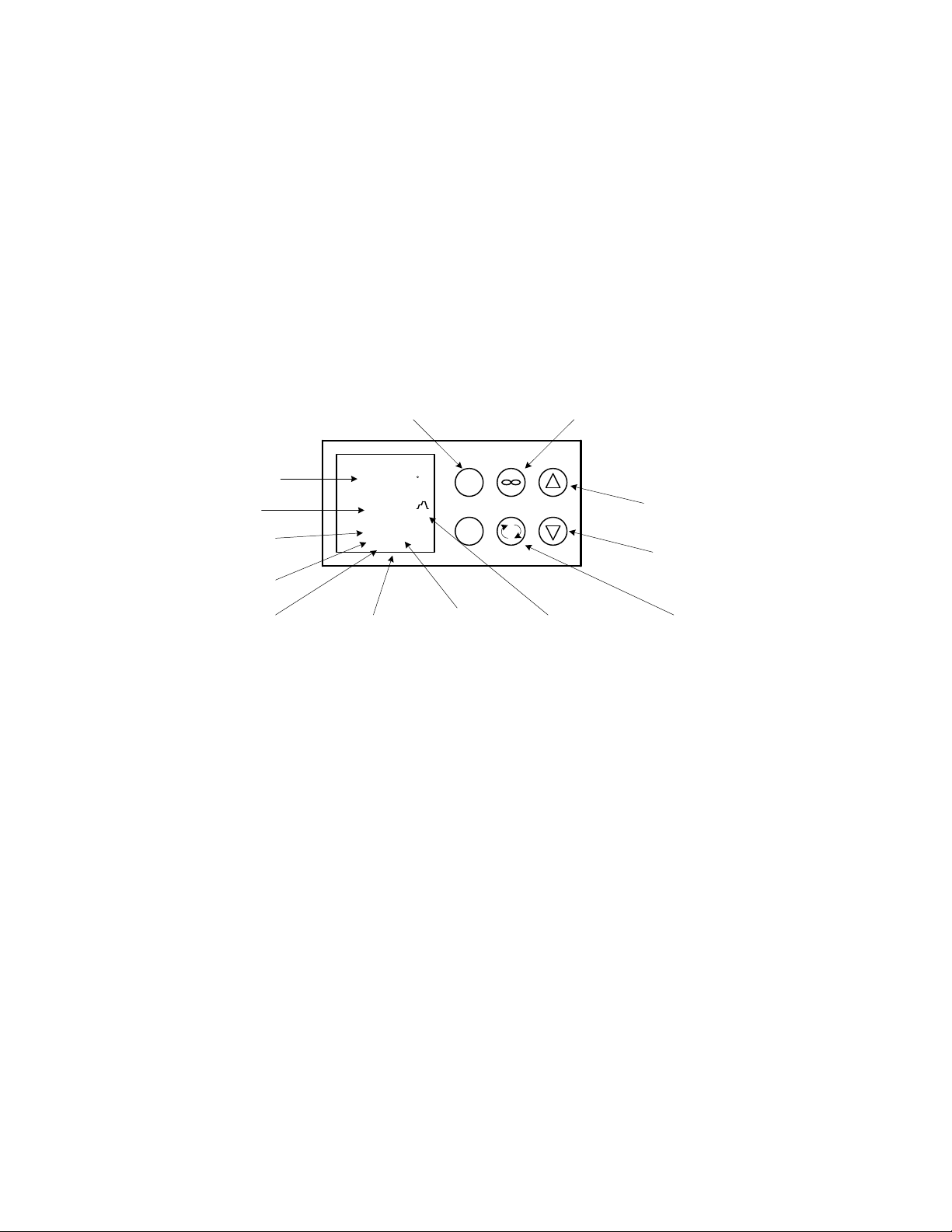
CONTROLLER KEYS AND DISPLAYS
5 6
OUTPUT 5 INDICATES
DAY OPERATION
OUTPUT 6 INDICATES
NIGHT OPERATION
Easy Zone Key 1
Starts and stops program
Infinite Key
Backs up one level or returns to normal display
mode
Up Arrow Key
Raises Setpoint or changes parameters
Ramp Symbol
Indicates program is running when active
Down Arrow Key
Lowers Setpoint or changes parameters
Advance Key
Scrolls through parameter list
Easy Zone Key 2
Not in use but can be programmed
Output 1
Active Heating Element
Light On
Indicates heating element is ON
Output 3
Active Calibration
Indicates calibration is ON for Day Cycle
Output 5
Day Cycle is active
Output 6
Night Cycle is active
Process Setpoint Display
Factory preprogrammed Setpoint
Actual Process
Temperature Display
Factory preprogrammed Setpoint
The SRI21D (LI15) comes from the factory preprogrammed to run a 12 hour day and 12 hour night cycle
using one setpoint. The setpoint from the factory is 20 degrees C and the program is set to start the day
cycle first.
Before Getting Started
Before getting started, it’s a good idea to become familiar with the control display and keys, terms, and
factory steps. Doing so will make getting started easier.
Controls
Normal Display Mode
Keys
Page 9

9
Terms
A1
Analog 1 input menu
CLoC
Setting hour, minutes, seconds for run time
dOW
Day Of Week
ED
Every Day
ENT1
Event output 1
ENT2
Event output 2
Event Timer
Factory installed timer (internal)
gLbL
Global menu
HoUr
Hour of day / night
i.CA
Calibration offset
JC
Jump Count
JL
Jump Loop
JS
Jump Step
Min
Minutes
SoAH
Soak
oPEr
Operation page
P1 PROF
Profile 1 of 4
rtCSet
Real Time Clock Set
SEC
Seconds
S.tyP
Active step type
Ti
Time
t.SPI
Target set point
Usr.s
User set
UStp
Unused Step
1P1, 2P1, 3P1, etc.
# indicates step, P1 indicates Profile 1
Page 10

Getting Started
There are four parts to setting up and running your SRI21D (LI15). Each part has instructions for powering
up the unit, setting the temperature setpoint, calibrating the offset value for day cycle and storing it into
memory, and calibrating the offset value for the night cycle and storing it into memory.
Powering Up Unit
To power up the unit, do the following:
On the front panel, turn the power OFF.
Plug the unit into a dedicated power source.
Turn the power ON.
The Power On light appears.
Turn the Set Over Temperature knob clockwise all the way over.
SETTING AND CALIBRATING DAY CYCLE
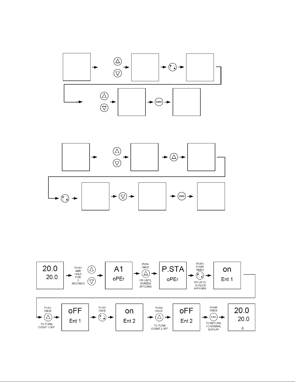
Use the up/down arrows to choose desired Setpoint. After Setpoint is entered, turn ON both Event Outputs.
To simulate Day Cycle, turn on Event Outputs following direction below.
Outputs 2,3, and 5 should be illuminated in the Bottom Display and light in incubator should be on. Allow unit
to stabilize for several hourse before calibrating.
Page 11
11
BEFORE CALIBRATION IS MADE MAKE SURE THAT INDICATOR 2, 3, 5, AND RAMP SYMBOL ARE ON INDICATING DAY
CYCLE ACTIVE. FIGURE OUT # VALUE OF OFFSET (ACTUAL TEMPERATURE MINUS PROCESS DISPLAY TEMPERATURE).
BELOW SHOWS WHERE AND HOW TO ENTER THE OFFSET # VALUE.
20.0
20.0
PUSH
AND
HOLD
FOR
5
SECONDS
PUSH
THREE
TIMES
i.CA
# VALUE
USE
UP AND
DOWN
BUTTONS
TO
ENTER
CALIBRATION
# VALUE
i.CA
# VALUE
PUSH
TWICE
20.0
20.0
TO RETURN
TO NORMAL
DISPLAY
A1
oPEr
OR UNTIL
SCREEN
APPEARS
AFTER THE OFFSET HAS BEEN ENTERED ALLOW UNIT TO STABALIZE. RECHECK TEMPERATURE AGAIN
AND IF CALIBRATION IS WITHIN EXCEPTABLE LIMITS THE OFFSET # VALUE NEEDS TO BE STORED INTO
MEMERY OR IT WILL REVERT BACK TO THE LAST # VALUE ON THE NEXT SWITCHING CYCLE.
BELOW SHOWS HOW TO STORE OFFSET # VALUE FOR THE DAY CYCLE
A1
SET
20.0
20.0
PUSH
AND
HOLD
FOR
10
SECONDS
PUSH
THREE
TIMES
LbL
g
SET
PUSH
FOUTEEN
TIMES
OR UNTIL
SCREEN
APPEARS
nonE
Usr.S Usr.S
SET 2
PUSH
ONCE
PUSH
TWICE
20.0
20.0
TO RETURN
TO NORMAL
DISPLAY
SELECTING SET 2 UNDER Usr.S SAVES THE OFFSET CALIBRATION FOR THE DAY CYCLE.
SETTING AND CALIBRATING NIGHT CYCLE
Use the up/down arrows to choose desired Setpoint. After Setpoint is entered, turn ON both Event Outputs.
To simulate Day Cycle, turn Event Outputs OFF to simulate Night Cycle. To turn OFF the Event Outputs,
follow directions below.
Outputs 2,3, and 5 should be OFF and 6 should be illuminated in the bottom of display. The lights inside
incubator should be off. Allow unit to stabilize for several hours before calibration.
Page 12

12
BEFORE CALIBRATION IS MADE MAKE SURE THAT INDICATOR 2, 3, 5, AND RAMP SYMBOL ARE ON INDICATING DAY
CYCLE ACTIVE. FIGURE OUT # VALUE OF OFFSET (ACTUAL TEMPERATURE MINUS PROCESS DISPLAY TEMPERATURE).
BELOW SHOWS WHERE AND HOW TO ENTER THE OFFSET # VALUE.
20.0
20.0
PUSH
AND
HOLD
FOR
5
SECONDS
PUSH
THREE
TIMES
i.CA
# VALUE
USE
UP AND
DOWN
BUTTONS
TO
ENTER
CALIBRATION
# VALUE
i.CA
# VALUE
PUSH
TWICE
20.0
20.0
TO RETURN
TO NORMAL
DISPLAY
A1
oPEr
OR UNTIL
SCREEN
APPEARS
AFTER THE OFFSET HAS BEEN ENTERED ALLOW UNIT TO STABALIZE. RECHECK TEMPERATURE AGAIN
AND IF CALIBRATION IS WITHIN EXCEPTABLE LIMITS THE OFFSET # VALUE NEEDS TO BE STORED INTO
MEMERY OR IT WILL REVERT BACK TO THE LAST # VALUE ON THE NEXT SWITCHING CYCLE.
BELOW SHOWS HOW TO STORE OFFSET # VALUE FOR THE DAY CYCLE
A1
SET
20.0
20.0
PUSH
AND
HOLD
FOR
10
SECONDS
PUSH
THREE
TIMES
LbL
g
SET
PUSH
FOUTEEN
TIMES
OR UNTIL
SCREEN
APPEARS
nonE
Usr.S Usr.S
SET 2
PUSH
ONCE
PUSH
TWICE
20.0
20.0
TO RETURN
TO NORMAL
DISPLAY
SELECTING SET 2 UNDER Usr.S SAVES THE OFFSET CALIBRATION FOR THE DAY CYCLE.
SETTING OVER TEMPERATURE LIMIT (OTL)
If using two different temperatures, pick the cycle with the higher Setpoint.
1. Allow unit to stabilize.
2. Turn OTL counter clockwise slowly until the OTL Light illuminates.
3. Turn OTL clockwise slowly until the OTL light goes out.
4. OTL is now set.
Page 13

13
20.0
20.0
USE UP OR
DOWN ARROWS
TO SELECT HOUR OF
DAY IN TOP
DISPLAY
hoU1
HOUR OF DAY
Mi1
ENTER REAL TIME
IN HOUR OF DAY
MINUTE OF HOUR
ENTER REAL TIME
IN MINUTE OF HOUR
TO SELECT MINUTE
OF HOUR IN TOP
DISPLAY
hoU2
HOUR OF DAY
hoU1
Mi1
TO SELECT
HOUR OF DAY IN TOP
DISPLAY
ENTER DAY CYCLE
START TIME IN
HOUR OF DAY
hoU2
Mi2
Mi2
TO SELECT HOUR
OF DAY IN TOP
DISPLAY
MINUTE OF HOUR
ENTER DAY CYCLE
START TIME IN
MINUTE OF HOUR
t.SP3
DAY CYCLE SET
POINT VALUE
TO SELECT DAY
CYCLE SET POINT
IN TOP DISPLAY
t.SP3
ENTER DAY CYCLE
SET POINT
hoU4
HOUR OF DAY
TO SELECT MINUTE
OF HOUR IN TOP
DISPLAY
hoU4
ENTER NIGHT
CYCLE START TIME
IN HOUR OF DAY
Mi4
MINUTE OF HOUR
TO SELECT MINUTE
OF HOUR IN TOP
DISPLAY
Mi4
ENTER NIGHT
CYCLE START TIME
IN MINUTE OF HOUR
t.SP5
NIGHT CYCLE
SET
POINT VALUE
TO SELECT NIGHT
CYCLE SET POINT
IN TOP DISPLAY
t.SP5
ENTER NIGHT
CYCLE
SET POINT
20.0
20.0
EZ1
20.0
20.0
PROGRAMING THE DAY AND NIGHT CYCLE
PROGRAMING THE DAY AND NIGHT CYCLE IS DONE IN JUST 8 EASY STEPS. THE FIRST TWO STEPS IS ENTERING THE REAL TIME IN HOURS
AND MINUTES OF THE DAY. THE NEXT THREE STEPS IS ENTERING THE DAY CYCLE START TIME IN HOUR AND MINUTES OF THE DAY PLUS
THE SET POINT IN WHICH THE DAY CYCLE WILL RUN. THE LAST THREE STEPS IS ENTERING THE NIGHT CYCLE START TIME IN HOUR AND
MINUTES OF THE DAY PLUS THE SET POINT WHICH THE NIGHT CYCLE WILL RUN.BELOW ARE INSTRUCTIONS ON HOW TO SCROLL
THROUGH THE 8 STEPS AND HOW TO CHANGE THE TIMES AND SET POINTS FOR THE REAL TIME, DAY CYCLE, AND NIGHT CYCLE.
PUSH
ONCE
PUSH
ONCE
USE UP OR
DOWN ARROWS
PUSH
ONCE
USE UP OR
DOWN ARROWS
PUSH
ONCE
USE UP OR
DOWN ARROWS
PUSH
ONCE
USE UP OR
DOWN ARROWS
PUSH
ONCE
USE UP OR
DOWN ARROWS
PUSH
ONCE
USE UP OR
DOWN ARROWS
USE UP OR
DOWN ARROWS
PUSH
ONCE
TO START
DAY/NIGHT
CYCLE
PROGRAM
PUSH
ONCE
PUSH
ONCE
TO RETURN
TO HOME
PAGE
HOME PAGE IS WHERE THE
CONTROL IS IN NORMAL CONTROL
MODE MEANING UPPER DISPLAY
IS PROCESS AND LOWER DISPLAY
IS SET POINT. TO START THE DAY
AND NIGHT CYCLE PROGRAM
PUSH THE EZ1 BUTTON ONCE.
PROGRAM IS
RUNNING WHEN
THE RAMP
SYMBOL IS
ILLUMINATED ON
THE RIGHT HAND
SIDE OF THE
DISPLAY
WHEN STARTING THE DAY AND NIGHT CYCLE IT WILL ALWAYS WAIT FOR THE DAY CYCLE FIRST. IF THE DAY TIME ENTERED IS EARLIER
THAN THE PROGRAM START TIME ( THE TIME YOU PUSH THE EZ1 BUTTON) THE PROGRAM WILL WAIT TILL THE NEXT DAY TO START.
Hou1 = REAL TIME IN HOURS OF DAY
Mi1 = REAL TIME IN MINUTES OF DAY
Hou2 = DAY CYCLE START TIME IN HOURS OF DAY
Mi2 = DAY CYCLE START TIME IN MINUTES OF THE HOUR
t
.SP3 = DAY CYCLE SET POINT VALUE
Hou4 = NIGHT CYCLE START TIME IN HOURS OF THE DAY
Mi4 = NIGHT CYCLE START TIME IN MINUTES OF THE HOUR
.SP5 = NIGHT CYCLE SET POINT VALUE
t
Page 14

14
MAINTENANCE
Section
The design of the chamber is such that periodic maintenance is kept to a minimum. NO
lubrication or adjustments of components is needed. If the incubator is used frequently at
temperatures below ambient room temperature or in any manner that increases moisture buildup within the chamber, a frequent defrosting schedule is recommended.
6.1 Defrosting: Frost can appear inside the unit due to moisture accumulating and
condensing on the coldest surface. The unit should be defrosted and cleaned on a
regular basis. The unit can be defrosted either manually or automatically. The water
drains from the chamber into an evaporation pan. Make sure to completely dry out the
interior when defrosting is complete.
A. Manual Defrost: Turn the unit off, open the door and allow the frost to melt. Then
clean the chamber following the directions in 6.2.
B. Automatic Defrost: the automatic defrost switch is located on the back of the unit.
It is an ON/OFF switch. In the ON position, the frost sensor is activated once every
twelve (12) hours. If the sensor detects frost, the compressor is shut down until the
frost has melted, and then the compressor is reactivated. The amount of time the
compressor is shut down is roughly one-half hour. During this time, the temperature
in the chamber will spike and the Main temperature Controller will cycle off, shutting
down the heating element. When the compressor is activated, the temperature will
stabilize at set point.
6.2 Cleaning: Clean the incubator chamber on a regular basis. Remove all interior parts
WARNING: Never clean the unit with alcohol or flammable cleaners with the unit connected to
the electrical supply. Always disconnect the unit from the electrical service when cleaning and
assure all volatile of flammable cleaners are evaporated and dry before reattaching the unit to
the power supply.
6.3 Compressor Compartment: Located at the back bottom of the unit, the compressor
6.4 Electrical Components: There is NO maintenance to electrical components. If the
and clean thoroughly with a disinfectant that is appropriate for your application.
Shelving should be cleaned with the same solution. Special care should be taken when
cleaning around sensing heads. DO NOT USE chlorine based bleaches or abrasives as
this can damage the interior. DO NOT USE spray cleaners that might leak through
openings and cracks and get on electrical parts or that may contain solvents that will
harm coatings.
compartment can collect dust which will inhibit proper air flow. This compartment should
be vacuumed out at least once every six (6) months to ensure maximum efficiency.
incubator fails to operate as specified, please review Section 7.0 Troubleshooting, prior to
calling for service.
Page 15

15
TROUBLESHOOTING AND SERVICE
TEMPERATURE
Temperature too high
1/ controller set too high-see section 5.5
2/ controller failed on – call Customer Service
Temperature too low
1/ Overtemperature Thermostat set too low – see section 5.8
2/ controller set too low – see section 5.5
3/ unit not recovered from door opening – wait for display to stop
changing.
4/ element failure – see if HEATING light is on; compare current
draw to data plate.
5/ controller failure – confirm with front panel lights that controller is
calling for heat.
6/ Overtemperture Thermostat failure – confirm with front panel
lights that Thermostat is operating correctly.
7/ loose connection – check shadow box for loose connections.
Unit will not heat over a temperature
that is below set point
1/ confirm that fan is moving and that amperage and voltage
match data plate – check fan motor and feel for air movement in
chamber
2/ confirm that set point is set high enough –turn Thermostat all
the way clockwise and see if HEATING light or OVERTEMP light
comes on
3/ check calibration – using independent certified thermometer,
follow instructions in section 5.6
Unit will not heat up at all
1/ verify that controller is asking for heat by looking for controller
light – if pilot light is not on continuously, there is a problem with the
controller.
2/check amperage – amperage should be virtually at maximum
rated (data plate) amperage.
3/ do all controller functions work?
4/ is the Thermostat set high enough? – for diagnostics, should be
fully clockwise with the pilot light never on.
5/ has the fuse/circuit breaker blown?
Indicated chamber temperature
unstable
Section
When troubleshooting, always make a visual inspection of the incubator and it’s control console to
find loose or disconnected wires which may be the source of the trouble. In the event the
incubator does not operate properly, check the following before calling for service.
Page 16

16
1/ ±0.1 may be normal
2/ is fan working? – fan must operate for uniformity
3/ is ambient room temperature radically changing – either door
opening or room airflow from heaters or air conditioning ? –
stabilize ambient conditions.
4/ sensor miss-located, damaged or wires may be damaged check mounts for control and Thermostat sensors, then trace wires
or tubing between sensors and controls.
5/ calibration sensitivity – call Customer Service
6/ Overtemperature set too low – be sure that Thermostat is more
than 5 degrees over desired set point; check if OVERTEMP pilot is
on continuously; turn controller knob completely clockwise to see if
problem solved then follow instructions in owner’s manual for
correct setting – see section 5.8
7/ electrical noise – remove nearby sources of RFI including
motors, arcing relays or radio transmitters.
8/ bad connection on temperature sensor or faulty sensor – check
connectors for continuity and mechanical soundness while
watching display for erratic behavior; check sensor and wiring for
mechanical damage.
9/ bad connections or faulty relay – check connectors for
mechanical soundness and look for corrosion around terminals or
signs of arcing or other visible deterioration.
Display and reference thermometer
don’t match
1/ calibration error – see section 5.9
2/ controller failure – evaluate if pilot light is operating correctly
3/ allow at least two hours to stabilize.
4/ see if reference thermometer is certified.
Calibrated at one temperature, but
not at another
Refer to Section 5.9
REFRIGERATION
Temperature can't get up to set point
1/ assure that power is going to heating coils.
2/ confirm that evaporator is calling for heat (check front panel
light).
3/ if light not coming on, check control set point and Thermostat
set point .
4/ confirm that fan is operating and airflow is not blocked.
5/ reset by turning unit off and on.
Unit won't cool
Page 17

17
If the compressor is running:
1/ see if condenser is cold but free of ice.
2/ be sure that fan is circulating air in the chamber and over the
compressor.
3/ confirm proper sensor location and operation.
4/ look for leaks in the chamber or around the door gasket.
5/ assure ample room around the unit as described in Installation
section 2.2
6/ If 1 through 7 has been tried and still not functioning correctly,
call customer service.
If compressor isn’t running:
1/ if too cold inside adjust “cold control”
located outside on bottom right rear
2/ check for non-operating relay
3/ confirm that compressor cooling fan motor is operable.
4/ check if motor has voltage to it.
5/ see if refrigeration is running too hot and thermal cutoff
activated:
a- dirty coil or poor circulation
b- coil next to heat source
c- ambient temperature too high
Ice build up in chamber
1/ Remove any open or exposed water in the chamber
2/ Search for leak in door gasket.
3/ Door being opened too often.
4/ Open container inside the chamber.
5/ Check tightness of seal around all chamber wire and plumbing
access to outside.
6/ Turn defrost switch on, Note: defrost switch must be turned off
for best temperature uniformity; If no defrost option available,
call Customer Service.
Making noise
1/ assure that fan is not miss-aligned.
2/ Steady internal clicking may be broken spring or valve – call
Customer Service.
MECHANICAL
Motor doesn't move
1/ if shaft spins freely: check connections to motor and check
voltage to motor.
2/ if shaft rubs or is frozen, relieve binding and retest.
Motor makes noise
1) Make sure that the fan or blower wheel is not contacting its
housing. Adjust the motor mounting bracket position to re-center
the fan or blower wheel, if necessary.
2) Check the fan or blower wheel for damage or out of balance
condition. Replace the fan or blower wheel if it is damaged or out
of balance.
3) Turn the motor shaft to make sure that it spins freely. If it binds
or the bearings make a rubbing or scrapping sound then replace
the motor.
Door not sealing
1/ Confirm that unit has not been damaged and body is square.
Page 18

18
OTHER
Unit heating all the time
1/ Adjust set point to room temperature. If the light goes out but is
still heating, replace the solid state relay.
2/ if cannot change any condition on the front panel, call Customer
Service.
Front panel displays are all off
Check for wire damage.
Unit or wall fuse/circuit breaker is
blown
1/ check wall power source.
2/ compare current draw and compare to specs on data plate.
3/ see what other loads are on the wall circuit.
Unit will not turn on
1/ check wall power source.
2/ check fuse/circuit breaker on unit or in wall.
3/ see if unit is on, e.g., fan or heater, and just controller is off.
4/ check all wiring connections, especially around the on/off
switch.
Contamination in chamber
1/ see cleaning procedure in operator’s manual
2/ develop and follow Standard operating procedure for specific
application; include definition of cleaning technique and
maintenance schedule.
Service
If none of the suggestions listed above have solved the problem, Customer Service should be
contacted for assistance.
Call 1-800-322-4897 and have the model number, serial number and voltage (listed on the data
plate on the side of the incubator) as your service representative will require it.
Page 19

19
PARTS LIST
Description
115V
220V
Circuit Breaker (20 amp)
1100500
1100500
Control Relay
7030536
7030536
Cooling Fan
4880564
4880564
Cord Set, European
NA
1850500
Cord Set, USA
1800529
1800537
Defrost Switch
7850579
7850579
Defrost Heater
2350536
2350536
Florescent Bulbs
4650538
4650538
Florescent Light Ballast
4660505
4660505
High Limit Control
1750862
1750862
Interior Outlet
6100525
6100526
Interior Outlet, European
NA
6100531
Low Limit Control
1750538
1750538
Main Temperature Control
9660513
9660513
Pilot Light, Green
4650554
4650554
Pilot Light, Red
4650553
4650553
Power Switch
7850532
7850532
Relay
7030511
7030520
Step Down Transformer
NA
8350521
System Logic Relay SSR
7030533
7030533
Thermal Limit Control, Non-Adjustable
1750506
1750506
Timer Defrost
8250507
8250507
Venting Fan
4880550
4880550
Section
Page 20
20
Unit Specifications
Shipping Weight
400 lbs.
Net Weight
280 lbs.
Exterior LxDxH (in.)
34.5 x 32 x 77
Interior LxDxH (in.)
27 x 23.5 x 57
Capacity
20.3 Cubic Ft
Capacity
257 Bottles
Temperature Range
0 to 45C
Temperature Uniformity
+.5 @ 20C
Page 21
21
TIMER
DEFROST
TIMER
8250507
1 2
3
14 13
MANUAL
DEFROST SWITCH
7850579
CF
CF
LOW LIMIT
THERMOSTAT
1750538
DOOR SWITCH
INTERIOR LIGHT
CF
9 1
RELAY
CONTACT
FOR 7030536
RELAY COIL FOR
7030536
COMPRESSOR
CONTROL COOLING FAN
4880550
COMPRESSOR
COOLING FAN
4880564
DEFROST
THERMOSTAT
R1
T1
S1
R1
X1
W1
Y1
L3
K3
J3
98
99
CF
CD
CE
WATLOW PM
9660513
RTD
SENSOR
6600520
14
13
RELAY COIL FOR
7030536
RC2
RELAY CONTACT
FOR 7030536
R2
34
21
1
2
4
OTP 1750862
4 TUBE
ELECTR ONIC BA LLAST
4660565
FLUORE SCE NT
FLUORE SCE NT
FLUORE SCE NT
FLUORE SCE NT
L2
K2
B5
D6
D5
1 2 3 4 5
6 7 8 9
SUB D 9 PIN
CONNECTOR
1650537
4
2
8
6
10
5
9
C1
C3
R3
R3
POWER CORD
1800529
CIRCUIT
BREAKER
1100500
POWER SWITCH 7850553
RELAY COIL
FOR 7030511
½ POWER RELAY
7030511
½ POWER RELAY
7030511
CHAMBER FAN
4880555
POWER ON LIGHT
4650554
OTL INDICATOR
4650553
HEATING LIGHT
4650554
LIMIT THERMOSTAT
43°C 1750506
SOLID STATE
RELAY
7030523
HEATING ELEMENT
2350536
12VDC
POWER
SUPPLY
6750507
LED LOGO
1750742
RED 22G
BLACK 22G
BLACKBLACK
BLACK
BLACK
BLACK
BLACK
BLACK
BLACK
BLACK
BLACK
BLACK
BLACK
BLACK
BLACK
BLACK
WHITE
WHITE
WHITE
WHITE
WHITE
WHITE
WHITE
WHITE
WHITE
WHITE
WHITE
WHITE
BLACK
BLUE BLUE
YELLOW YELLOW
GREY
BROWN
BROWN
ORANGE
ORANGE
ORANGE
RED
RED 22G
RED 22G
RED 22G
BLACK 22G
BLACK 22G
BLACK 18G
WHITE 18G
INTERIOR OUTLET
6100525
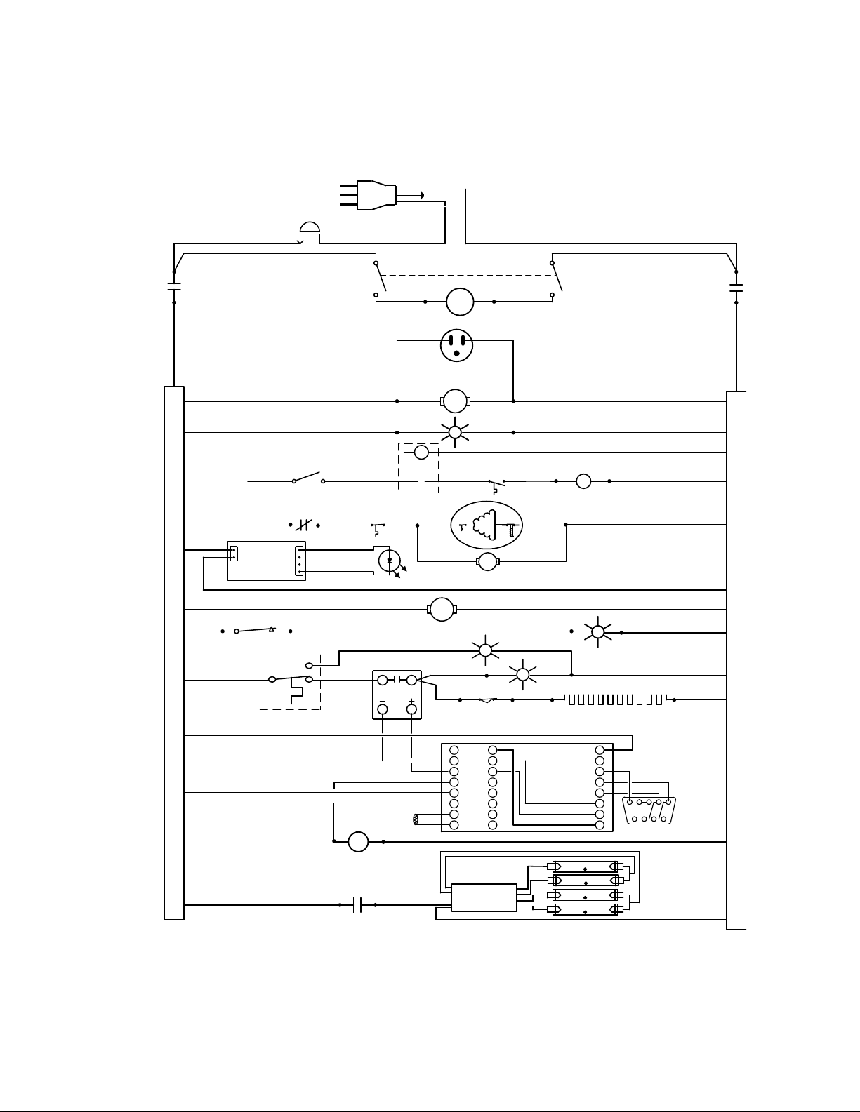
Wire Diagram
SRI21D (LI15) 100-120V
Page 22
22
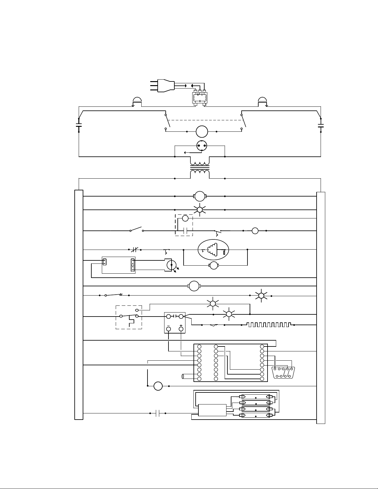
Wire Diagram
TIMER
DEFROST
TIMER
8250507
1 2
3
14 13
MANUAL
DEFROST SWITCH
7850579
CF
CF
LOW LIMIT
THERMOSTAT
1750538
DOOR SWITCH
INTERIOR LIGHT
CF
9 1
RELAY
CONTACT
FOR 7030536
RELAY COIL FOR
7030536
COMPRESSOR
CONTROL COOLING FAN
4880550
COMPRESSOR
COOLING FAN
4880564
DEFROST
THERMOSTAT
R1
T1
S1
R1
X1
W1
Y1
L3
K3
J3
98
99
CF
CD
CE
WATLOW PM
9660513
RTD
SENSOR
6600520
14
13
RELAY COIL FOR
7030536
RC2
RELAY CONTACT
FOR 7030536
R2
34
21
1
2
4
OTP 1750862
4 TUBE
ELECTRONIC BALLAST
4660565
FLUORESCENT
FLUORESCENT
FLUORESCENT
FLUORESCENT
2800502
EMI
FILTER
L2
K2
B5
D6
D5
1 2 3 4 5
6 7 8 9
SUB D 9 PIN
CONNECTOR
1650537
4
2
8
6
10
5
9
C1
C3
R3
R3
POWER CORD
1800541
CIRCUIT
BREAKER
1100500
CIRCUIT
BREAKER
1100500
POWER SWITCH 7850553
RELAY COIL
FOR 7030520
INTERIOR OUTLET
6100532
STEP DOWN
TRANSFORMER
8350321
½ POWER RELAY
7030520
½ POWER RELAY
7030520
CHAMBER FAN
4880555
POWER ON LIGHT
4650554
OTL INDICATOR
4650553
HEATING LIGHT
4650554
LIMIT THERMOSTAT
43°C 1750506
SOLID STATE
RELAY
7030523
HEATING ELEMENT
2350536
12VDC
POWER
SUPPLY
6750507
LED LOGO
1750742
RED 22G
BLACK 22G
BLACKBLACK
BLACK
BLACK
BLACK
BLACK
BLACK
BLACK
BLACK
BLACK
BLACK
BLACK
BLACK
BLACK
BLACK
BLACK
BLACK
BLACK
WHITE WHITE
WHITE
WHITE
WHITE
WHITE
WHITE
WHITE
WHITE
WHITE
WHITE
WHITE
WHITE
WHITE
WHITE
WHITE
BLACK
BLUE BLUE
YELLOW YELLOW
GREY
BROWN
BROWN
ORANGE
ORANGE
ORANGE
RED
RED 22G
RED 22G
RED 22G
BLACK 22G
BLACK 22G
BLACK 18G
WHITE 18G
SRI21D-2 (LI15-2) 220-240V
 Loading...