

Page 1
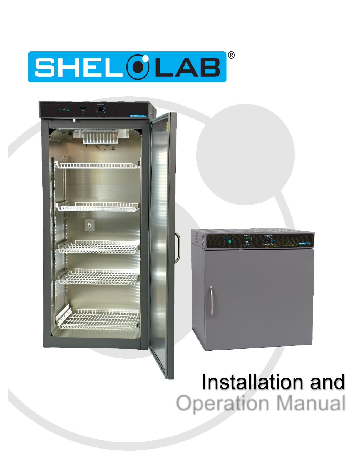
Installation and
Operation Manual
SRI3P, SRI6P, SRI20P
Previously designated as
LI3PW, LI6P, LI20P
BOD INCUBATORS 100 - 120 Voltage
Page 2
Sheldon Refrigerated BOD Incubators 100 – 120 Voltage
Installation and Operation Manual
Revision: April 29, 2014
Pictured on Cover: SRI20P (left) - SRI6P (right)
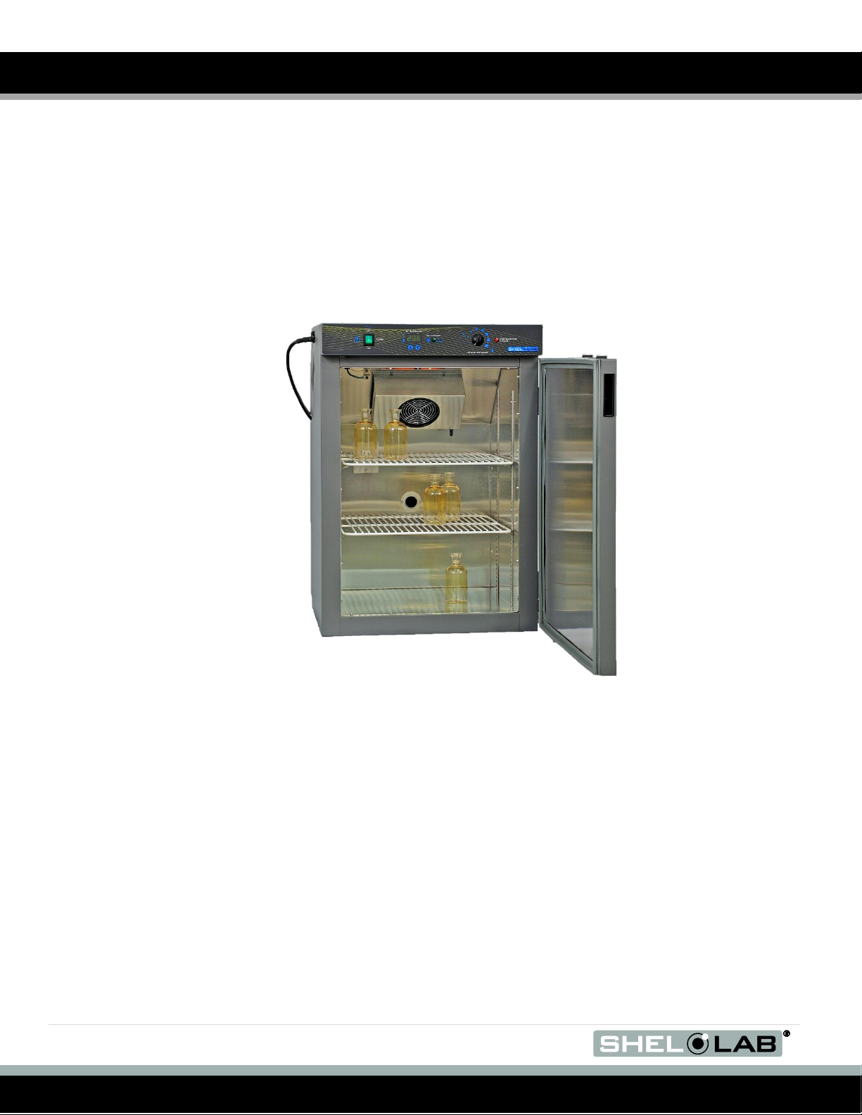
SRI3P
These units are TÜV CUE listed as incubators and radiant warmers for professional, industrial, or
educational use where the preparation or testing of materials is done at approximately atmospheric
pressure and no flammable, volatile, or combustible materials are being heated.
These units have been tested to the following requirements:
CAN/CSA C22.2 No. 61010-1:2012
CAN/CSA C22.2 No. 61010-2-010 + R:2009
UL 61010A-2-010:2002
UL 61010-1:2012
EN 61010-1:2010
EN 61010-2-010:2003
IEC 61010-1:2010
IEC 61010-2-010:2003
2 | P a g e
Page 3

.
TABLE OF CONTENTS
INTRODUCTION ..................................................................................................................................................... 4
General Safety Considerations ........................................................................................................................... 4
Engineering Improvements ................................................................................................................................. 5
Contacting Assistance ......................................................................................................................................... 5
RECEIVING YOUR INCUBATOR .......................................................................................................................... 6
Inspecting the Shipment ...................................................................................................................................... 6
Returning the Shipment ...................................................................................................................................... 6
Recording Data Plate Information ....................................................................................................................... 7
GRAPHIC SYMBOLS ............................................................................................................................................. 8
INSTALLATION .................................................................................................................................................... 10
Location ............................................................................................................................................................. 10
Lifting and Handling .......................................................................................................................................... 10
Leveling ............................................................................................................................................................. 10
Install Side Air Ducts, SRI20P ........................................................................................................................... 11
Shelving Installation .......................................................................................................................................... 12
Power Source .................................................................................................................................................... 15
Cleaning ............................................................................................................................................................ 15
CONTROL PANEL OVERVIEW ........................................................................................................................... 16
OPERATION ......................................................................................................................................................... 17
Theory of Operation .......................................................................................................................................... 17
Door Alarm ........................................................................................................................................................ 17
Setting Up the Incubator ................................................................................................................................... 18
Set the Temperature Set Point .......................................................................................................................... 18
Calibrate the Temperature display .................................................................................................................... 19
Set the Over Temperature Limit ........................................................................................................................ 20
Silencing the Door Ajar Alarm ........................................................................................................................... 20
Loading the Incubator ....................................................................................................................................... 20
Attaching equipment to the Interior Accessory Outlet ....................................................................................... 20
Humidifying the Incubator ................................................................................................................................. 21
USER MAINTENANCE ......................................................................................................................................... 22
Cleaning ............................................................................................................................................................ 22
Disinfecting ........................................................................................................................................................ 22
UNIT SPECIFICATIONS ....................................................................................................................................... 24
Weight ............................................................................................................................................................... 24
Dimensions ........................................................................................................................................................ 24
Capacity ............................................................................................................................................................ 24
Shelf Capacity by Weight .................................................................................................................................. 25
Temperature ...................................................................................................................................................... 25
Power ................................................................................................................................................................ 25
PARTS AND CONSUMABLES ............................................................................................................................ 26
Ordering Parts and Consumables ..................................................................................................................... 26
3 | P a g e
Page 4

INTRODUCTION
Thank you for purchasing a Sheldon Manufacturing refrigerated BOD Peltier incubator. We know that in
today’s competitive marketplace, customers have many choices when it comes to constant temperature
equipment. We appreciate you choosing ours. Our continued reputation as a leading laboratory product
manufacturer rests with your satisfaction. Sheldon Manufacturing, Inc. stands behind our products, and
we will be here if you need us.
These incubators are intended for professional, industrial, or educational use as BOD incubators. They
are not designed for use in hazardous or household locations.
Before you use the incubator read this entire manual carefully to understand how to install, operate, and
maintain the incubator in a safe manner. Keep this manual available for use by all incubator operators.
Ensure that all operators are given appropriate training before the incubator begins service.
Note: This unit is not designed or intended for the growth, cultivation, incubation, or storage of fruit flies
(Drosophila melanogaster). Improper use of this unit, including use with fruit flies, will void any
warranty. Other units are specifically manufactured for fruit fly application, and you should consult
your Shel Lab dealer or customer service representative in order to identify another model suitable
for your application.
GENERAL SAFETY CONSIDERATIONS
Your incubator and its recommended accessories are designed and tested to meet strict safety
requirements. Only use this equipment for its intended application; any alterations or modifications void
the warranty. Failure to follow the guidelines and instructions in this manual may create a protection
impairment by disabling or interfering with the unit’s safety features. This can result in injury or death.
For continued safe operation of your incubator, always follow basic safety precautions including:
Follow all local or regional ordinances in your area regarding the use of this unit. If you have any
questions about local regulations, please contact the appropriate local agency.
Use only approved accessories. Do not modify system components. Any alterations or
modifications to your incubator can be dangerous and void your warranty.
Always plug the incubator power cord into an earth grounded electrical outlet that conforms to
national and local electrical codes. If the incubator is not grounded properly, parts such as knobs
and controls can conduct electricity and cause serious injury.
Avoid damaging the power cord. Do not bend it excessively, step on it, or place heavy objects on
it. A damaged cord can be a shock or fire hazard. Never use a power cord if it is damaged.
Do not position the incubator in such a manner as to make it difficult to unplug the unit in the
event of an emergency.
Do not attempt to move the incubator while in operation.
4 | P a g e
Page 5

.
INTRODUCTION (CONTINUED)
ENGINEERING IMPROVEMENTS
Sheldon Manufacturing continually improves all of its products. As a result, engineering changes and
improvements are made from time to time. Therefore, some changes, modifications, and improvements
may not be covered in this manual. If your unit’s operating characteristics or appearance differs from
those described in this manual, please contact your Shel Lab dealer or distributor for assistance.
CONTACTING ASSISTANCE
If you are unable to resolve a technical issue with your incubator, please contact Sheldon Technical
Support. Phone hours for Sheldon Technical Support are 6am – 4:30pm Pacific Coast Time (west coast
of the United States, UTC -8). Please have the following information ready when calling or emailing
Technical Support: the model number and the serial number (see page 7).
EMAIL: tech@shellab.com PHONE: 1-800-322-4897 extension 2, or (503) 640-3000 FAX: (503) 6401366
Sheldon Manufacturing INC.
P.O. Box 627
Cornelius, OR 97113
5 | P a g e
Page 6
Model
Standard Shelves
Sliding Shelves
Leveling Feet
SRI3P 2 0
4
SRI6P 2 0
4
SRI20P
4 1 4
Model
Side Air Ducts
SRI3P
0
SRI6P
0
SRI20P
2
RECEIVING YOUR INCUBATOR
Before leaving the factory, all incubators are packaged in high-quality shipping materials to provide
protection from transportation-related damage.
When an incubator leaves the factory, safe delivery becomes the responsibility of the carrier. Damage
sustained during transit is not covered by the warranty.
When you receive your incubator, inspect it for concealed loss or damage to its interior and exterior. If
you find any damage to the incubator, then follow the carrier’s procedure for claiming damage or loss.
INSPECTING THE SHIPMENT
Carefully inspect the shipping carton for damage. Report any damage to the carrier service that delivered
the incubator. If the carton is not damaged, open the carton and remove the contents.
Verify that the correct number of shelves, shelf slides, and leveling feet have been included (see the
following table for quantities).
Included accessories
Carefully check all packaging before discarding. Save the shipping carton until you are sure everything
works properly.
RETURNING THE SHIPMENT
If you must return the incubator for any reason, first contact your service representative for a return of
material authorization (RMA). You must provide the unit’s data plate information. See Recording Data
Plate Information below.
6 | P a g e
Page 7

.
Model Number
Serial Number
RECEIVING (CONTINUED)
RECORDING DATA PLATE INFORMATION
Locate the data plate on the back of the incubator on the top right. The data plate contains the incubator
model number and serial number. Enter this information below for future reference.
Date Plate Information
7 | P a g e
Page 8
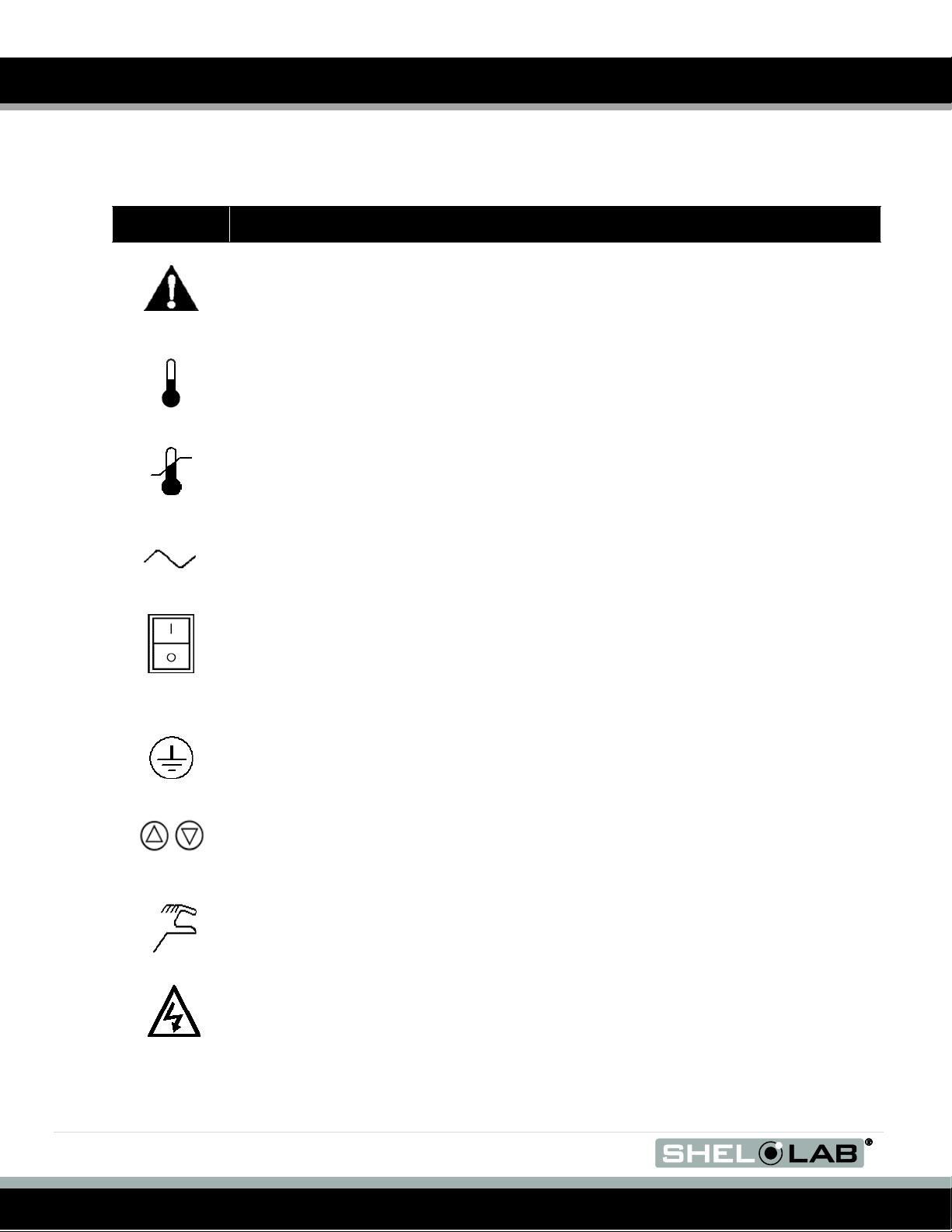
Symbol
Definition
Indicates that you should consult your service manual for further instructions.
Indique que l'opérateur doit consulter le manuel d'utilisation pour y trouver les instructions
complémentaires.
Indicates Temperature
Repère température
Indicates the Over Temperature Limit system
Indique le système de dépassement de temperature
Indicates AC Power
Repère le courant alternatif
Indicates I/ON and O/OFF
I repère de la position MARCHE de l'interrupteur d'alimentation
O repère de la position ARRÊT de l'interrupteur d'alimentation
Indicates protective earth ground
Repère terre électrique
Indicates UP and DOWN respectively
Touches de déplacements respectifs vers le HAUT et le BA
Indicates Manually Adjustable
Indique un bouton réglable manuellement
Indicates Potential Shock Hazard
Signale danger électrique
GRAPHIC SYMBOLS
The incubator is provided with graphic symbols on its interior and exterior surfaces. These symbols
identify hazards, as well as the functions of the adjustable components, and important notes in the user
manual.
8 | P a g e
Page 9

.
Symbol
Definition
WEEE Directive compliant logo
Indicates the unit should be recycled (Not disposed of in land-fill)
Indique l’appareil doit être recyclé (Ne pas jeter dans une décharge)
GRAPHIC SYMBOLS (CONTINUED)
9 | P a g e
Page 10

INSTALLATION
This incubator is intended for use indoors, at room temperatures between 15C and 30C (59F and
86F), at no greater than 80% Relative Humidity at 25C (77F). Allow a minimum of 4 inches (10cm)
between the incubator and walls or partitions and 2 inches (5cm) of clearance above the top of the
incubator for unobstructed airflow. Position the unit so the end-user has access to the power plug.
Operating the unit outside of these conditions may adversely affect the temperature range and
stability.
For conditions outside of those listed above, please contact your distributor or Sheldon Sales to explore
other incubator options suited to your laboratory or production environment.
LOCATION
When selecting a location to install the incubator, consider all environmental conditions that can affect
unit’s effective temperature range, uniformity, and stability. For example:
Ovens, autoclaves, and any device that produces significant radiant heat
Heating and cooling ducts, or other sources of fast moving air currents
High-traffic areas
Direct sunlight
LIFTING AND HANDLING
The incubator is heavy and care should be taken to use appropriate lifting devices that are sufficiently
rated for these loads. Follow these guidelines when lifting and handling the incubator.
Lift the incubator only from its bottom surface.
Doors, handles, and knobs are not adequate for lifting or stabilization.
Restrain the incubator completely while lifting or transporting so it cannot tip.
Remove all moving parts, such as shelves and trays. Secure the doors in the closed position
during transfer.
LEVELING
Make sure that the incubator is level and stable. Each incubator ships with four leveling feet. Insert one
leveling foot into each of the four holes in the bottom corners of the incubator. Stand the incubator
upright. Then, adjust the foot at each corner until the incubator stands level and solid without rocking. To
raise a foot, turn it in a counterclockwise direction; to lower a foot, turn it in a clockwise direction.
Note: To prevent damage when moving the incubator, turn each of the four leveling feet completely
10 | P a g e
clockwise.
Page 11

.
INSTALLATION (CONTINUED)
INSTALL SIDE AIR DUCTS, SRI20P
Two (2) side air ducts are packed with the accessories of the SRI20P. Install the air ducts from the corner
top and bottom hooks into the provided slots on the sides of the chamber. The SRI3P and SRI6P
incubators do not use Side Air Ducts.
Figure 1: SRI20P Air Duct Panel
Note: The air duct panels play an important role maintaining even heat distribution inside the SRI20P’s
incubation chamber. Failure to install both air duct panels may adversely impact the incubator’s
temperature uniformity.
11 | P a g e
Page 12

INSTALLATION (CONTINUED)
SHELVING INSTALLATION
SRI3P Shelf Installation
Perform the following steps to install the SRI3P incubator’s wire basket shelves:
1. Install the shelf clips in the slots located on the sides of the chamber interior, front and back.
2. Squeeze each clip, insert the top tab first, and then the bottom tab using a rocking motion.
3. Hang the wire shelves from the clips.
Figure 2: SRI3P Shelving Clips
12 | P a g e
Page 13

.
Figure 5: Standard Shelf Hung
From Mounting Bracket
INSTALLATION (CONTINUED)
SRI6P and SRI20P Standard Shelving Installation
Perform the following steps to install the SRI6P and SRI20P incubator standard shelves:
Figure 3: Standard Shelf Mounting Bracket Installation
1. Laterally insert the mounting bracket’s 2 pairs of twin tabs (front and back) into the slots on the
sides of the incubator chamber.
2. Slide the bracket down so that the tabs are securely seated in the mounting slots.
3. Repeat the process on the opposite side of the chamber with the second mounting bracket.
Figure 4: Standard Mounting
Bracket Installed
4. Hang 1 shelf off the 2 installed mounting brackets.
13 | P a g e
Page 14

Figure 6: Sliding Shelf Mounting
Bracket Installation
Figure 7: Sliding Shelf Mounting
Bracket Installation
Figure 8: Sliding Mounting Bracket
Screws
Figure 9: Sliding Mounting Bracket
Front Screw Installed
INSTALLATION (CONTINUED)
SRI6P and SRI20P Sliding Shelf Installation
Note: The SRI6P does not come with a sliding shelf. Sliding shelves for the SRI6P must be purchased
separately.
1. Laterally insert the sliding mounting bracket’s 2 pairs of twin tabs (front and back) into the slots on
the sides of the incubator chamber. See Figure 6.
2. Slide the bracket down so that the tabs are securely seated in the mounting slots. See Figure 7.
Secure the bottom flange of the sliding mounting bracket to the side of the chamber interior by
threading and screwing in 2 screws, at the front and back of the flange. See Figures 8 and 9.
14 | P a g e
Page 15

.
INSTALLATION (CONTINUED)
3. Repeat the process on the opposite side of the chamber with the second sliding mounting
bracket.
4. Hang 1 shelf from the 2 installed sliding mounting brackets.
POWER SOURCE
Check the data plate for voltage and ampere requirements before making a connection. If the
requirements match your power source, plug the power cord into an earth grounded outlet. These units
are provided with a 100 – 120V 9ft, 5 in (2.86m), Nema 5-15P power cord. Supplied voltage must not
vary more than 10% from the data plate rating. Damage to the incubator may result if supplied
voltage varies more than 10%.
These incubators are intended for a 50/60 Hz application. Use a separate circuit to prevent loss of
product due to overloading or circuit failure.
Note: Electrical supply to the incubator must conform to all national and local electrical codes.
CLEANING
The incubator interior was cleaned at the factory but not sterilized. See the Cleaning topic in the User
Maintenance section for more information
15 | P a g e
Page 16

CONTROL PANEL OVERVIEW
Figure 10: Control Panel SRI3P
Power Switch
The main power switch on the control panel (green lighted I/O) controls all power to the unit and must be
in the I/ON position before any systems are operational. The switch will be lighted when in the I/ON
position.
Main Temperature Control and Green Digital Display
The SRIP incubator control panels comes with a green digital display that shows the temperature within
the incubator unit’s chamber accurate to 0.1°C, and the user-selected temperature set point. The control
is marked Set Temperature and consists of an UP/DOWN arrow pad for inputting set point temperatures,
adjusting the time, and performing calibrations.
Heating and Cooling Light
The green pilot light located beneath the label TEC ACTIVATED should be ON whenever the Peltier TEC
device is actively heating or cooling the chamber. This light should be ON nearly all of the time.
Set Over Temperature
This graduated dial sets the temperature set point for the Over Temperature Limit backup system. The
OTL System operates independently of the Main Temperature Controller, and prevents uncontrolled
heating of the Main Chamber in the event of a Main Temperature Controller failure. For more details,
please see the explanation of the Over Temperature Limit System in the Operation Section.
OTL Light
The red pilot light marked OVER TEMPERATURE ACTIVATED will illuminate when the Over
Temperature Limit System has taken control of the incubator. Under normal operating conditions this pilot
lamp should never illuminate.
Fuse
Located on the top back of the unit inside the cord inlet, the fuse protects against over current conditions.
If the fuse blows, the unit will shut down. For your safety and the safety of laboratory personnel the cause
of a blown fuse should be determined prior to replacing it.
16 | P a g e
Page 17

.
OPERATION
THEORY OF OPERATION
Each SRIP incubator uses a Peltier thermoelectric cooling-and-heating device and an air circulating fan in
conjunction with a Proportional-Integrative-Derivative feedback temperature controller board to achieve
precise control over temperature levels in the incubator chamber. The temperature sensor located in the
air stream senses temperature deviations from the set point. The PID Controller Board uses feedback
from the sensor and error calculation functions to ensure a high degree of thermal stability – avoiding
overshooting or undershooting the user-selected set point when heating and cooling the chamber. This
results in precise and highly efficient cooling and heating operations with minimum power use. The
circulating fan provides even air distribution throughout the chamber and assures temperature uniformity
around the unit’s entire shelf space.
DOOR ALARM
The SRIP incubator is equipped with a magnetic induction door alarm which activates when the door is
open and the sensor components are out of range of one another for more than sixty seconds (1 minute).
When the alarm system is active an audio alarm will sound and the control panel display will flash.
Leaving the door open for extended periods will disrupt temperature uniformity within the incubator
chamber, and may result in significantly increased power use as the temperature controller board
attempts to compensate for the disruption.
ACCESSORY COMPATIBILITY
Make sure that any accessory equipment you will be using inside an SRIP incubator can safely and
effectively operate within your selected temperature range.
THE OVER TEMPERATURE LIMIT SYSTEM
The OTL is a backup heating control system that operates independently of the unit’s digital Main
Temperature Controller board. In the event of a failure of the controller board while in its heating mode,
the OTL system prevents runaway heating by depowering the peltier thermal electric heating and cooling
unit.
The OTL will not prevent a rise in heat caused by a failure of the peltier itself.
Note: The OTL system should be tested at least once per year using the Set The Over Temperature
Limit procedure.
17 | P a g e
Page 18

Figure 11: SRI3P Control Details
OPERATION (CONTINUED)
SETTING UP THE INCUBATOR
Perform the following steps and procedures to prepare the incubator for use each time it is installed in a
new location:
1. Verify the workspace’s power supply and incubator’s data plate requirements match.
2. Check that the fuse is installed in the power inlet.
3. Plug the power cord into an earth grounded electrical outlet.
4. Place the Power switch in the ON position.
5. Complete the following procedures in order:
a. Set the Temperature Set Point
b. Calibrate the Temperature Display
c. Set the Over Temperature Limit Control
SET THE TEMPERATURE SET POINT
Perform these steps to prepare the unit for calibration.
1. Turn the Over Temperature Limit control dial clockwise to the maximum position indicated by
the largest dot. This prevents the Over Temperature Limit system from interfering with the set
point and calibration procedures.
2. Press either the Up or Down key one time on the Temperature Control panel to activate the
temperature set point mode. The Set Temperature digital display will start to blink, going from
bright to dim. Some models may briefly display the letters “SP” to indicate a Set Point is being
displayed. While blinking, the Set Temperature display shows an adjustable temperature set
point.
3. To change the set point, press either the Up or the Down key to adjust the set point up or down.
If neither key is pressed within 5 seconds, the Set Temperature display stops blinking and returns
to displaying the current temperature of the incubator.
4. Adjust the set point to the temperature you will use during normal operations.
5. Wait 5 seconds after entering your set point. The display will stop flashing, and the set point is
now saved in the controller. The incubator will now automatically adjust to match your set point.
18 | P a g e
Page 19

.
OPERATION (CONTINUED)
CALIBRATE THE TEMPERATURE DISPLAY
Allow the incubator at least 24 hours to stabilize at its operational set point before performing a
calibration. Always use a certified temperature sensing reference device that is regularly calibrated to
0.1°C by an independent party to conduct temperature verifications or calibrations. For best results use a
remote sensing device.
1. Place the temperature sensor of a calibrated reference device inside the incubator as close as
possible to the chamber’s geometric center. Check that the sensor is not in direct contact with the
shelving.
Note: A thermocouple sensor probe’s sleeve may be taped to the shelving, as long as the exposed copper
end is 2 inches (5cm) above the shelf. An exposed sensor probe in direct contact with the shelving
may experience heat sinking, which can result in an inaccurate temperature reading.
2. Allow the temperature to re-stabilize after closing the door. The reference device’s temperature
measurement should not change for at least one (1) hour after a significant disruption for the
chamber to be considered stabilized.
3. If the reference device’s and the incubator’s temperature readings are the same, or the difference
between the two falls within the acceptable range of your laboratory protocol after one (1) hour of
stability, the incubator is calibrated.
4. If there is a difference between the two (2) readings, and that offset falls outside your laboratory
protocol’s acceptable range, adjust the incubator’s temperature display to match the reference
device’s reading. See the next step. If the door was briefly opened to take a reading, wait fifteen
minutes for the temperature to stabilize before correcting for the offset.
5. Press and hold both the UP and DOWN arrows simultaneously. The Temperature Display will
begin flashing and display the current temperature value. Adjust the current value until it
matches the reference device’s temperature reading. This will enter the offset into the unit’s
temperature controller board.
6. After matching the unit’s current value to that of the reference device, wait five seconds. The
incubator’s Temperature Display will cease flashing, and the incubator will begin heating or
cooling to compensate for the entered temperature offset.
7. Allow the incubator one (1) hour to stabilize after reaching the new temperature.
8. Compare the reference device’s reading with the incubator’s. If the reference device’s and the
incubator’s temperature readings are the same or fall within the range of your laboratory protocol,
the incubator is now calibrated.
9. If the two readings are not the same or fall outside your laboratory protocol, repeat steps 5 – 8.
10. If the temperature readings of the incubator and the reference device still fall outside your
laboratory protocol after three calibration attempts, contact Sheldon Technical Support for
assistance.
19 | P a g e
Page 20

OPERATION (CONTINUED)
SET THE OVER TEMPERATURE LIMIT
Perform the following steps to set up the Over Temperature Limit system for use.
1. If you have not done so already, turn the Set Over Temperature Limit control dial clockwise to
the maximum position. This allows the Set Temperature control to stabilize.
2. Then turn the Over Temperature Limit control dial counterclockwise until the Over Temp Limit
Activated light illuminates.
3. Slowly turn the Over Temperature Limit control dial clockwise until the light turns off.
4. This adjusts the Over Temperature Limit control to approximately 1˚C above the temperature
configured by the Set Temperature control.
SILENCING THE DOOR AJAR ALARM
If the door alarm needs to be silenced, close the door, which will reset the timer. For prolonged periods
with the door open, the unit should be switched to the OFF position. If the door alarm continues to sound
when the door is fully closed, the position of the black tab-like door alarm sensor, mounted on the front
left side of the door frame overhang, can be adjusted using a screwdriver. Loosen the screws just enough
to slide the sensor and adjust. Do not remove the screws.
LOADING THE INCUBATOR
Place items on the shelves inside the incubator chamber as evenly spaced as possible. Good spacing
allows for maximum air circulation and a higher degree of temperature uniformity.
ATTACHING EQUIPMENT TO THE INTERIOR ACCESSORY OUTLET
The incubator has a 1A (maximum) accessory outlet located inside the chamber. The power switch on the
front panel controls power to the accessory outlet. This outlet can power equipment such as magnetic
stirrers, rockers, etc. Do not attach any equipment drawing more than 1A to this outlet.
Accessory equipment may produce additional heat. This heat could affect the temperature range and
uniformity of this incubator. If you are using the interior accessory outlet, you should check that the
incubator operates within required temperatures when the accessory equipment is installed and
operating.
20 | P a g e
Page 21

.
OPERATION (CONTINUED)
HUMIDIFYING THE INCUBATOR
Placing only a small number of petri dishes or open media containers in the incubator chamber may lead
to excessive drying of sample media. Unusually dry environmental conditions may also contribute to
sample drying. To counteract this, Sheldon Manufacturing offers an optional humidity collection pan and
tubing accessory kit: Part Number 9900708. The kit redirects moisture that normally condenses on the
heat sink fins of the Peltier TEC heating and cooling device, and uses it to humidify the incubator. After
ordering and receiving the kit, place the stainless steel pan on the lowest chamber surface. Connect the
tubing that comes with the kit to the port on the back of the Peltier duct cover. Run the tubing down the
back of the incubator behind the shelves, and secure the end of the tubing inside the pan. The pan is
supplied with a copper slug to help prevent microbial contamination.
The humidifying kit is intended for use while running small loads. High workspace ambient humidity, or
applications that generate high levels of humidity, may result in excessive condensation on the Peltier
TEC unit. Overloading the unit with culture media can also generate excessive humidity from sample
media evaporation and blocking air flow pathways through the shelf space. Water dripping from the
Peltier duct cover at the top of the chamber onto the shelf space and floor is symptomatic of excessive
chamber humidity, and may damage the incubator.
21 | P a g e
Page 22

USER MAINTENANCE
Warning: Prior to any maintenance or service on this unit, disconnect the power cord from the power supply.
Avertissement: Avant d'effectuer toute maintenance ou entretien de cet appareil, débrancher le cordon
secteur de la source d'alimentation.
If a hazardous material/substance has spilled in the incubator immediately initiate your site’s Hazardous
Material Spill Containment protocol. Contact your local Site Safety Officer and follow instructions per the
site policy and procedures.
Periodic cleaning and disinfection are required to prevent microbiological contamination.
CLEANING
Note: The incubator chamber should be cleaned and disinfected prior to use.
Perform the following steps to clean incubator.
1. Remove all of the interior parts (shelves, racks, and any additional items), if assembled.
2. Clean the incubator with a mild soap and water solution, including all corners.
3. Rinse with distilled water and wipe dry with a soft cloth. Do not use deionized water.
4. Take special care when cleaning around the door alarm and temperature sensor heads, and the
chamber’s electrical outlet to prevent damage.
Warning: Never clean the unit with alcohol or flammable cleaners.
Avertissement: Ne jamais nettoyer l'appareil à l'alcool ou avec des nettoyants inflammables.
Note: Do not use spray cleaners or disinfectants that might leak through openings and cracks and coat
electrical components, or that contain solvents that will harm coatings. Do not use chlorine-based
bleaches or abrasives; they will damage the chamber liner.
DISINFECTING
Disinfect the incubator on a regular basis. Perform the below steps to disinfect the incubator:
1. Remove all of the interior parts (shelves, racks, and any additional items), if assembled. Disinfect
the Incubator, including all corners and the access port, using a suitable disinfectant. Take
special care when cleaning around sensing heads to prevent damage and around the door
gasket so as not to impair the positive seal.
2. Disinfect the incubator using commercially available disinfectants that are non-corrosive, nonabrasive, and suitable for use on stainless steel, aluminum, painted steel surfaces. Contact your
local Site Safety Officer for detailed information for the proper disinfectants suitable for your
operation and laboratory protocol.
22 | P a g e
Page 23

.
MAINTENANCE (CONTINUED)
Periodically, inspect the door latch, trim, catch, and gasket for signs of deterioration. Failure to maintain
the integrity of the door system shortens the life span of the incubator.
Electrical components do not require maintenance. If the incubator fails to operate as specified, please
contact your Shel Lab Dealer or Sheldon Technical Support for assistance.
23 | P a g e
Page 24

Model
Shipping
Net Weight
SRI3P
145lbs / 65.8kg
105lbs / 47.6kg
SRI6P
245lbs / 111.1kg
125lbs / 56.7kg
SRI20P
405lbs / 183.7kg
246lbs / 111.6kg
Model
Exterior W × D × H
Interior W × D × H
SRI3P
24.1 x 21.3x 33.8 in
18.9 x 16.9 x 26.4 in
SRI6P
30 x 31.5 x 33.5 in
25.5 x 24.0 x 18.5 in
SRI20P
30 x 31.5 x 69.5 in
25.5 x 24.0 x 54.5 in
Model
Exterior W × D × H
Interior W × D × H
SRI3P
61.2 x 54.1 x 98.55 cm
48 x 42.9 x 67.06 cm
SRI6P
76.2 x 80.01 x 85.09 cm
64.8 x 61.0 x 47.1 cm
SRI20P
76.20 x 80.01 x 176.53 cm
64.77 x 60.96 x 138.43 cm
Model
Cubic Feet
Liters
SRI3P
3.5
99
SRI6P
6.55
185.53
SRI20P
19.30
546.57
UNIT SPECIFICATIONS
These incubators are 100 - 120 voltage units. Please refer to the incubator’s data plate for individual
electrical specifications.
Technical data specified applies to units with standard equipment at an ambient temperature of 25°C and
a voltage fluctuation of ±10%. The temperatures specified are determined in accordance to factory
standard following DIN 12880 respecting the recommended wall clearances of 10% of the height, width,
and depth of the inner chamber. All indications are average values, typical for units produced in the
series. We reserve the right to alter technical specifications at all times.
WEIGHT
DIMENSIONS
In inches
In Centimeters
CAPACITY
24 | P a g e
Page 25

.
Model
Per Shelf
Total
SRI3P
35lbs / 15.9kg
70lbs / 31.7kg
SRI6P
75lbs / 34kg
150lbs / 34kg
SRI20P
75lbs / 34kg
375lbs / 170kg
Model
Temp Range
Uniformity
Stability
SRI3P
15 to 40C
+/-0.5 @ 20C
+/-0.1C @ 20C
SRI6P
15 to 40C
+/-0.5 @ 20C
+/-0.1C @ 20C
SRI20P
15 to 40C
+/-0.5 @ 20C
+/-0.1C @ 20C
Model
Voltage
Amperage
Frequency
SRI3P
100 - 120V
4
50/60 Hz
SRI6P
100 - 120V
4
50/60 Hz
SRI20P
100 - 120V
5.5
50/60 Hz
UNIT SPECIFICATIONS (CONTINUED)
SHELF CAPACITY BY WEIGHT
TEMPERATURE
POWER
25 | P a g e
Page 26

Description
Part Number
Feet, Adjustable Glide
2700506
Power Cord, USA
1800510
Shelves (2) SRI3P
6800529
Shelf Clip (4 needed per shelf) SRI3P
1250512
Standard Shelf SRI6P SRI20P
6800525
Static Shelf Mount Bracket SRI6P SRI20P
5220942
Sliding Shelf Mounting Kit (2 Brackets) SRI6P SRI20P
9490560
Fuse 6.3A
3300515
Lab Stopper
7750517
Gasket, Magnetic Door SRI3P (28.25 inches X 22.25
Inches)
3450758
Gasket, Magnetic Door SRI6P (29 inches X 26 inches)
3450743
Gasket, Magnetic Door SRI20P (29 inches X 62 inches)
3450732
Optional Humidity Reservoir Pan and Tubing
9900708
PARTS AND CONSUMABLES
ORDERING PARTS AND CONSUMABLES
If you have the Part Number for an item, you may order the item directly from Sheldon Manufacturing by
calling (503) 646-3000 Ext. 136. If you are uncertain that you have the correct Part Number or if you need
that specific part, please contact Sheldon Technical Support for help at 1-800-322-4879 or (503) 640-
3000. Please have the model number and serial number of the BACTRON ready, as Tech Support will
need this information to match your workstation with its correct part.
26 | P a g e
Page 27

 Loading...