

Page 1
Installation and
Operation Manual
SMI2, SMI6, SMI7, SMI11, SMI12
Previously designated as
GI2, GI6, GI7, GI11, GI12
SMI INCUBATOR 100 – 120 Voltage
Page 2

Sheldon Manufacturing Incubator 100 – 120 Voltage
Installation and Operation Manual
Part number: 4861572-1,
Revised: December 18, 2013
These units are TUV CUE listed as general-purpose air incubators for professional, industrial, or
educational use where the preparation or testing of materials is done at approximately atmospheric
pressure and no flammable, volatile, or combustible materials are being heated.
These units have been tested to the following requirements:
CAN/CSA C22.2 No. 61010-1:2012
CAN/CSA C22.2 No. 61010-2-010 + R:2009
UL 61010A-2-010:2002
UL 61010-1:2012
EN 61010-1:2010
EN 61010-2-010:2003
IEC 61010-1:2010
IEC 61010-2-010:2003
2 | P a g e
Page 3

.
TABLE OF CONTENTS
INTRODUCTION ..................................................................................................................................................... 4
General Safety Considerations ........................................................................................................................... 4
Engineering Improvements ................................................................................................................................. 4
RECEIVING YOUR INCUBATOR .......................................................................................................................... 5
Inspecting the Shipment ...................................................................................................................................... 5
Returning the Shipment ...................................................................................................................................... 5
Recording Data Plate Information ....................................................................................................................... 5
GRAPHIC SYMBOLS ............................................................................................................................................. 6
CONTROL PANEL OVERVIEW ............................................................................................................................. 7
Power On/Off Switch ........................................................................................................................................... 7
Power On Light .................................................................................................................................................... 7
Set Temperature Control ..................................................................................................................................... 7
Set Over Temp Limit Control ............................................................................................................................... 7
Heating Activated Light ....................................................................................................................................... 7
Over Temp Limit Activated Light ......................................................................................................................... 8
Fuse .................................................................................................................................................................... 8
INSTALLATION ...................................................................................................................................................... 9
Location ............................................................................................................................................................... 9
Lifting and Handling ............................................................................................................................................ 9
Leveling ............................................................................................................................................................... 9
Shelves .............................................................................................................................................................. 10
Power Source .................................................................................................................................................... 10
Cleaning ............................................................................................................................................................ 11
OPERATION ......................................................................................................................................................... 12
Turning On the Incubator .................................................................................................................................. 12
Adjusting the Set Temperature Control ............................................................................................................. 12
Calibrating the Set Temperature Control .......................................................................................................... 12
Setting the Over Temperature Limit Control ..................................................................................................... 13
Attaching equipment to the Interior Accessory Outlet ....................................................................................... 13
Humidifying the Incubator ................................................................................................................................. 13
USER MAINTENANCE ......................................................................................................................................... 14
Cleaning ............................................................................................................................................................ 14
Disinfecting ........................................................................................................................................................ 14
INCUBATOR SPECIFICATIONS ......................................................................................................................... 16
Weight ............................................................................................................................................................... 16
Dimensions ........................................................................................................................................................ 16
Capacity ............................................................................................................................................................ 17
Temperature ...................................................................................................................................................... 17
Power ................................................................................................................................................................ 17
PARTS LIST ......................................................................................................................................................... 18
Parts .................................................................................................................................................................. 18
3 | P a g e
Page 4

INTRODUCTION
Thank you for purchasing our product. We know that in today’s competitive market place, customers have
many choices when it comes to constant temperature equipment. We appreciate you choosing our
quality product. Our continued reputation as a leading laboratory product manufacturer rests with you.
Sheldon Manufacturing, Inc. stands behind our products and want to let you know we are here if you
need us.
These incubators are not intended for use at hazardous or household locations.
Before you use the incubator, read this entire manual carefully to understand how to install, operate, and
maintain the incubator in a safe manner.
Keep this manual available for use by all incubator operators. Ensure that all operators are given
appropriate training before the incubator begins service.
Note: Failure to follow the guidelines and instructions in this manual may create a protection impairment
by disabling or interfering with the unit’s safety features. This may result in injury or death.
GENERAL SAFETY CONSIDERATIONS
Your incubator and its recommended accessories are designed and tested to meet strict safety
requirements.
For continued safe operation of your incubator, always follow basic safety precautions including:
Read this entire manual before using the incubator.
Obey any city, county, or other ordinances in your area regarding the use of this incubator.
Use only approved accessories. Do not modify system components. Any alterations or
modifications to your incubator can be dangerous and void your warranty.
Always plug the incubator power cord into a grounded electrical outlet that conforms to national
and local electrical codes. If the incubator is not grounded properly, parts such as knobs and
controls can conduct electricity and cause serious injury.
Avoid damaging the power cord. Do not bend it excessively, step on it, or place heavy objects on
it. A damaged cord can be a shock or fire hazard. Never use a power cord if it is damaged.
ENGINEERING IMPROVEMENTS
Sheldon Manufacturing continually improves all of its products. As a result, engineering changes and
improvements are made from time to time. Therefore, some changes, modifications, and improvements
may not be covered in this manual. If your unit’s operating characteristics or appearance differs from
those described in this manual, please contact your Shel Lab® dealer or distributor for assistance.
4 | P a g e
Page 5
.
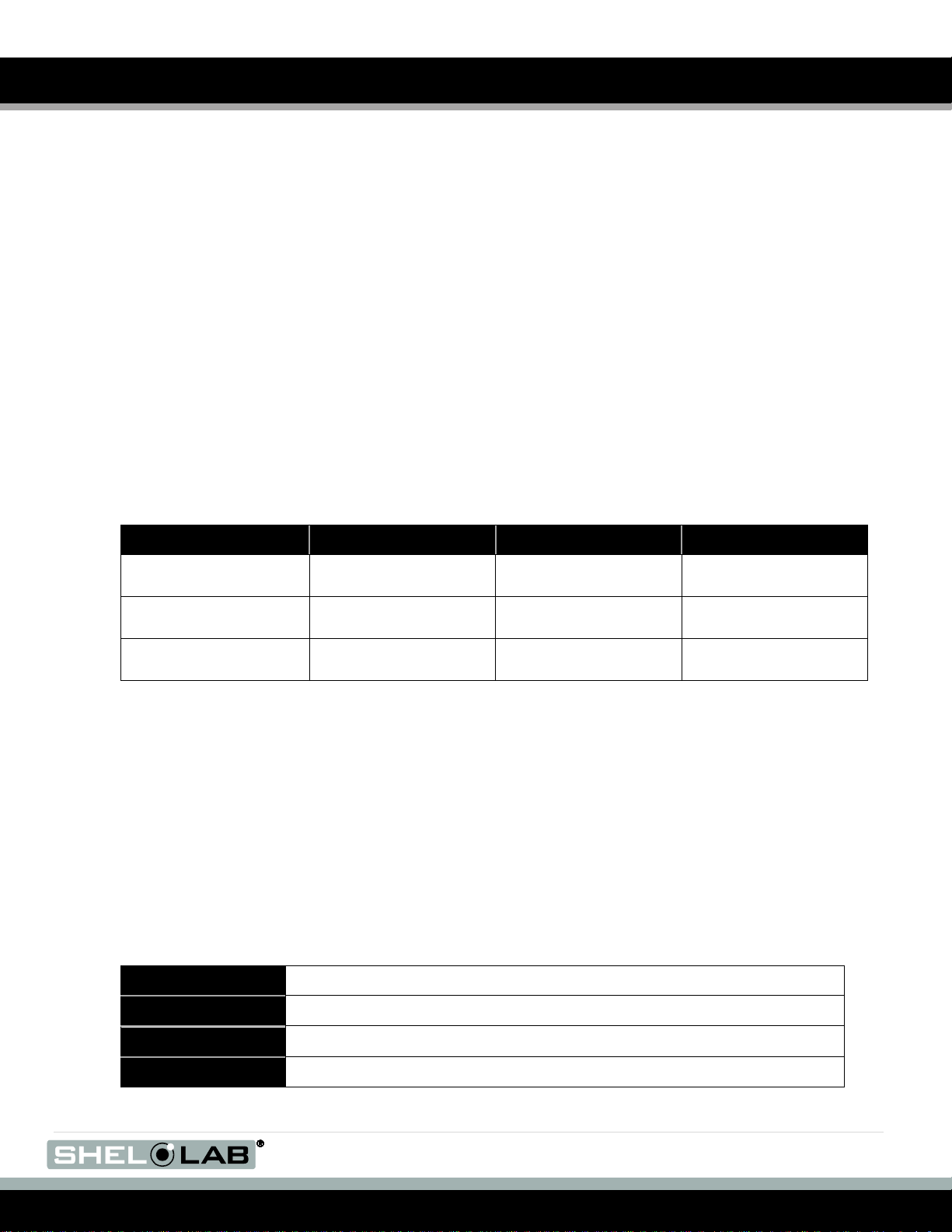
Model
Shelves
Shelf Slides
Leveling Feet
SMI2, SMI7
(GI2, GI7)
2 4 4
SMI6
(GI6)
3 6 4
SMI11, SMI12
(GI11, GI12)
6
12
4
Model Number
Serial Number
Part Number
Voltage
RECEIVING YOUR INCUBATOR
Before leaving our factory, all incubators are packaged in high-quality shipping materials to provide
protection from transportation-related damage.
When an incubator leaves our factory, safe delivery becomes the responsibility of the carrier. Damage
sustained during transit is not covered by the incubator warranty.
When you receive your incubator, inspect it for concealed loss or damage to its interior and exterior. If
you find any damage to the incubator, then follow the carrier’s procedure for claiming damage or loss.
The unit should come with an Installation and Operation Manual, warranty card, and a Certificate of
Compliance.
INSPECTING THE SHIPMENT
Carefully inspect the shipping carton for damage. Report any damage to the carrier service that delivered
the incubator. If the carton is not damaged, open the carton and remove the contents.
Verify that the correct number of shelves, shelf slides, and leveling feet have been included (see the
following table for quantities).
Included accessories
Carefully check all packaging before discarding. Save the shipping carton until you are sure everything
works properly.
RETURNING THE SHIPMENT
If you must return the incubator for any reason, first contact your service representative for authorization
(RMA). You must provide the data plate information. See Recording Data Plate Information below.
RECORDING DATA PLATE INFORMATION
Locate the data plate at the back of the incubator. The data plate contains the incubator model number
and serial number. Enter this information below for future reference.
Date Plate Information
5 | P a g e
Page 6
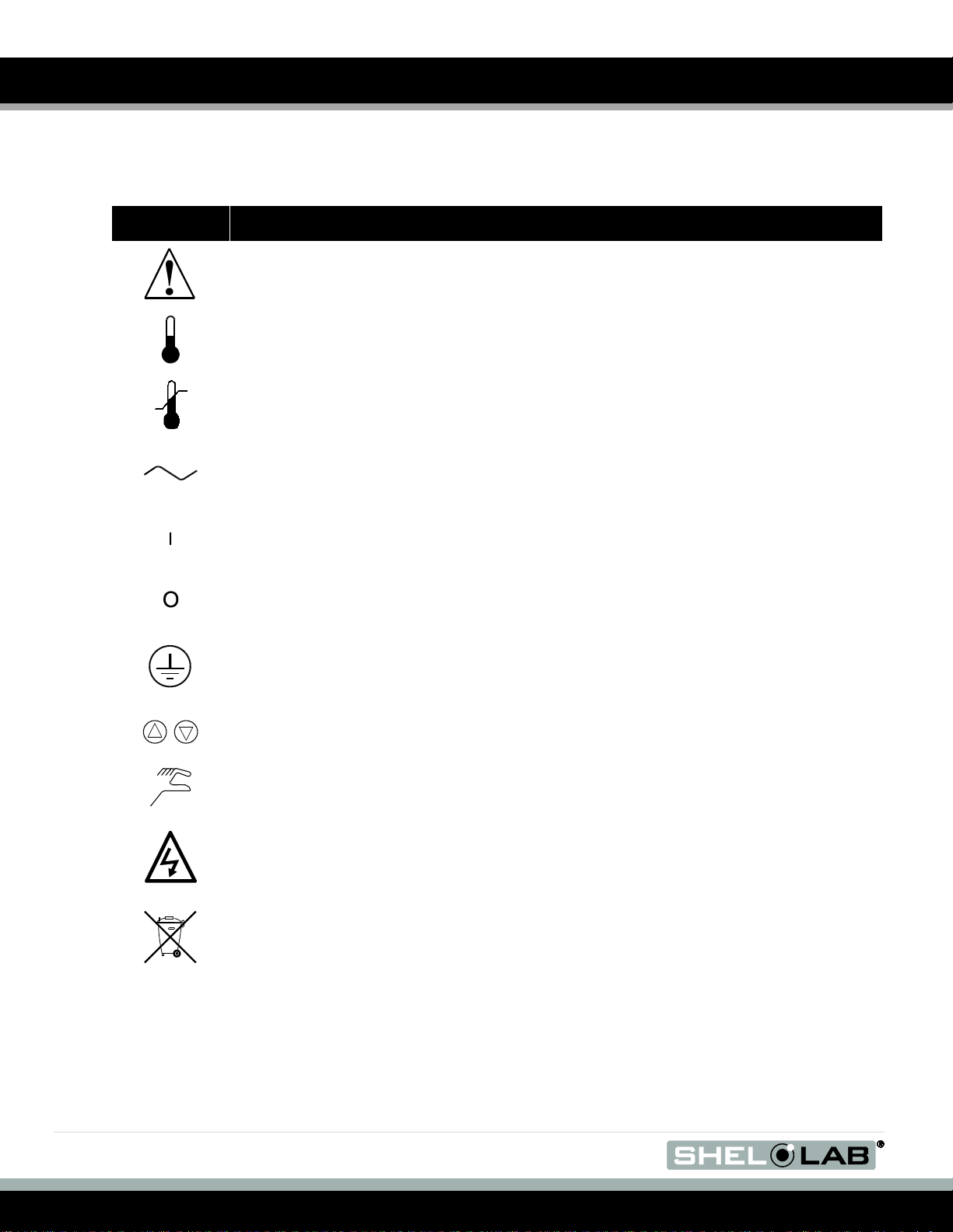
Symbol
Definition
Indicates that you should consult your operator’s manual for further instructions.
Indique que l'opérateur doit consulter le manuel d'utilisation pour y trouver les instructions
complémentaires.
Indicates Temperature
Indique un affichage de la temperature
Indicates Over Temperature Protection
Indique le système de dépassement de temperature
Indicates AC Power
Repère le courant alternatif
Indicates the power is ON
Repère de la position MARCHE de l'interrupteur d'alimentation
Indicates the power is OFF
Repère de la position ARRÊT de l'interrupteur d'alimentation
Indicates Protective Earthground
Repère terre électrique
Indicates Up and Down respectively
Touches de déplacements respectifs vers le HAUT et le BAS
Indicates Manually Adjustable
Signale un élément réglable manuellement
Indicates Potential Shock Hazard
Signale un danger électrique
Indicates Incubator should be recycled (Not disposed of in land-fill)
Indique l’appareil doit être recyclé (Ne pas jeter dans une décharge)
GRAPHIC SYMBOLS
Your incubator has graphic symbols on the control panel and adjacent to the power inlet. The symbols
identify hazards and the function of the adjustable components, as well as important notes in the user
manual.
6 | P a g e
Page 7

.
CONTROL PANEL OVERVIEW
Figure 1
POWER ON/OFF SWITCH
The Power On/Off switch controls power to the incubator. To turn on the incubator, place the switch in the
On (I) position. Turn off the incubator by placing the switch in the Off (0) position. The Set Temperature
control and the Power On light illuminate when the incubator is on.
POWER ON LIGHT
This green light is on when power is supplied to the incubator and the Power On/Off switch is in the On
(1) position; the light is off when the Power On/Off switch is in the Off (0) position.
SET TEMPERATURE CONTROL
The Set Temperature control is the incubator’s main control. It consists of a digital display and Up/Down
keys that can be used for inputting set point temperature and calibration.
SET OVER TEMP LIMIT CONTROL
You can set the over temperature thermostat using the Set Over Temp Limit control. This control is
equipped with a graduated dial (larger circles, larger value; smaller circles, smaller value). The dial
requires a flat-edged tool to adjust the setting to eliminate accidental changes. The Set Over Temp Limit
control is completely independent of the Set Temperature control and guards against a Set Temperature
control failure. A failure of the Set Temperature control can permit the temperature to rise past the set
point. If the temperature rises to the Set Over Temperature Limit set point, the Set Over Temperature
Limit thermostat takes control of the heating element and permits continued use of the incubator until the
problem can be resolved or service can be arranged.
Operating the incubator for an extended period using only the Set Over Temperature Limit affects
temperature accuracy.
HEATING ACTIVATED LIGHT
This green light is on while the incubator heats up to the set point configured by the Set Temperature
control; the light blinks when the temperature reaches the set point.
7 | P a g e
Page 8

CONTROL PANEL OVERVIEW (CONTINUED)
OVER TEMP LIMIT ACTIVATED LIGHT
This red light is on when the Set Over Temperature Limit control is activated. This light should not
illuminate under normal operating conditions.
FUSE
The fuse is located within the power inlet and offers protection against power source variations. The
incubator will not operate with a blown or missing fuse.
8 | P a g e
Page 9

.
INSTALLATION
The end user can perform installation. Only use this equipment for its intended application; any alterations
or modifications void the warranty. Local city, county, or other ordinances govern the use of this
equipment. If you have any questions about local requirements, please contact the appropriate local
agency.
This incubator is intended for use indoors, at room temperatures between 15 and 30C, at no greater
than 80% Relative Humidity (at 25C), and with a supply voltage that does not vary by more than 10%.
Contact customer service for operating conditions outside these limits (refer to the back cover for contact
information).
LOCATION
When selecting a location to install the incubator, consider all conditions that can affect performance, for
example:
Heating and cooling ducts
Stoves and Autoclaves
Direct sun
Fast moving air currents
High-traffic areas
Allow a minimum of 10 cm between the incubator and walls or partitions and 5 cm of clearance above the
top of the incubator for unobstructed airflow. Position the unit so the end-user has access to the power
plug.
LIFTING AND HANDLING
The incubator is heavy and care should be taken to use appropriate lifting devices that are sufficiently
rated for these loads. Follow these guidelines when lifting and handling the incubator:
Lift incubators only from their bottom surface.
Doors, handles, and knobs are not adequate for lifting or stabilization.
Restrain the incubator completely while lifting or transporting so it cannot tip.
Remove all moving parts, such as shelves and trays, and lock doors in the closed position during
transfer to prevent shifting and damage.
LEVELING
You must make sure that the incubator is level and stable. Each incubator ships with four leveling feet.
Insert one leveling foot into each of the four holes in the bottom corners of the incubator. Stand the
incubator upright. Then, adjust the foot at each corner until the incubator stands level and solid without
rocking. To raise a foot, turn it in a counterclockwise direction; to lower a foot, turn it in a clockwise
direction.
Note: To prevent damage when moving the incubator, turn each of the four leveling feet completely
clockwise.
9 | P a g e
Page 10

INSTALLATION (CONTINUED)
SHELVES
To install the incubator shelves perform the following:
1. Hold the shelf slide at about a 10° angle (Figure 2A).
2. Insert the hooked tab into the vertical slot at the desired height (Figure 2B).
3. Push the slide into the horizontal slots.
4. Repeat for shelf slide at the same height on the opposite side of the incubator.
5. Place a shelf on the shelf slides. Repeat this procedure for additional shelves as needed.
Figure 2
POWER SOURCE
Check the data plate for voltage and ampere requirements before making a connection. If the
requirements match your power source, plug the power cord into a grounded outlet. A 6ft, Nema 5-15P
power cord is provided with the unit. Supplied voltage must not vary more than 10% from the data
plate rating. Damage to the incubator may result if supplied voltage varies more than 10%.
These incubators are intended for a 50/60 Hz application. Use a separate circuit to prevent loss of
product due to overloading or circuit failure. The SMI12 (GI12) unit requires two power cords/sources;
each chamber operates independently.
Note: Electrical supply to the incubator must conform to all national and local electrical codes.
10 | P a g e
Page 11

.
INSTALLATION (CONTINUED)
Warning: Multiple power sources. Risk of electrical shock or damage to unit. Disconnection of all power
sources is required prior to servicing.
Attention: Sources d'alimentation multiples. Risque de décharge électrique ou d'endommagement de
l'unité. Débrancher toutes les sources d'alimentation avant l'entretien.
CLEANING
The incubator interior was cleaned at the factory but not sterilized. See the Cleaning topic in the User
Maintenance section for more information.
11 | P a g e
Page 12

OPERATION
TURNING ON THE INCUBATOR
Perform the below steps to turn on the incubator:
1. Verify the power supply and incubator data plate match.
2. Check that the fuse is installed in the power inlet of the incubator.
3. Plug the power cord into a grounded electrical outlet.
4. Place the Power switch in the ON position.
5. If needed (for example, if the incubator was just installed), complete the Calibrating the Set
Temperature Control procedure. Then, to set the over temperature limit, complete the Setting
the Over Temperature Limit Control procedure. To set the temperature, complete the
Adjusting the Set Temperature Control procedure. When you finish configuring the incubator
temperatures, load the chamber.
ADJUSTING THE SET TEMPERATURE CONTROL
Perform the below steps to adjust the Set Temperature Control:
1. Turn the Set Over Temperature Limit control dial clockwise to the maximum position indicated
by the largest dot. This allows the Set Temperature control to be set and calibrated without
interruption from the Set Over Temperature Limit setting.
2. Press either the Up or Down key one time to enter set point mode. The Set Temperature digital
display will start to blink, going from bright to dim. While blinking, the Set Temperature display
shows the set point. Some models may first display “SP” and then flash the set point.
3. To change the set point, press either the Up or the Down key. If neither key is pressed within five
(5) seconds, the Set Temperature display stops blinking and displays the temperature of the
incubator.
4. Allow the incubator at least 24 hours to stabilize.
CALIBRATING THE SET TEMPERATURE CONTROL
Only calibrate the incubator after it has been installed in its working environment and is stable at its set
point for 24 hours. Perform the below steps to calibrate your incubator:
1. Place a certified reference thermometer in the chamber either directly inside or through the
access tube at the top-left of the incubator. Check that the thermometer does not touch any
shelving. If you place the thermometer directly inside the chamber, tape the thermometer to a
Petri dish to elevate it off the shelf and keep the scale in view.
2. Allow the temperature to stabilize again (wait until the thermometer measurement does not
change for one hour).
12 | P a g e
3. Compare the Set Temperature display with the measurement of the reference thermometer.
4. If there is a difference, place the Set Temperature control into calibration mode by pressing both
the Up and Down keys at the same time for approximately five (5) seconds until two (2) decimals
are flashing. Some models may show °C first, and then flash the current temperature reading.
Page 13

.
OPERATION (CONTINUED)
5. While blinking, calibrate the Set Temperature display by pressing the Up or Down key until it
displays the correct value. After you set the temperature value, wait approximately five (5)
seconds for the calibration to complete and the display to stop blinking.
6. Allow the incubator temperature to stabilize again (wait until the thermometer measurement does
not change for one hour) and recalibrate if necessary.
SETTING THE OVER TEMPERATURE LIMIT CONTROL
Perform the below steps to adjust the Set Over Temperature Limit control:
1. Turn the Set Over Temp Limit control dial clockwise to the maximum position (this allows the
Set Temperature control to stabilize).
2. Adjust the Set Temperature control to 1˚C above the desired set point, and then allow the
incubator to stabilize (wait until temperature is constant for one hour).
3. Turn the Set Over Temp Limit control dial counterclockwise until the Over Temp Limit Activated
light illuminates.
4. Then, slowly turn the Set Over Temp Limit control dial clockwise until the light turns off.
5. Return the Set Temperature control back to the desired set point.
6. This adjusts the Set Over Temp Limit control to approximately 1˚C over the temperature
configured by the Set Temperature control. If using the Over Temperature feature, test it
annually.
Note: Test the Over Temperature feature annually.
ATTACHING EQUIPMENT TO THE INTERIOR ACCESSORY OUTLET
This unit has a 1A (maximum) accessory outlet that is located inside the chamber. The power switch on
the front panel controls power to the accessory outlet. This outlet can power equipment such as magnetic
stirrers, rockers, etc. Do not attach any equipment drawing more than 1A to this outlet.
Accessory equipment may produce additional heat. This heat could affect the temperature range of this
incubator. If you are using the interior accessory outlet, you should check that the incubator operates
within required temperatures when the accessory equipment is installed and operating.
HUMIDIFYING THE INCUBATOR
Long-term use of a large water container such as, a humidifier pan, may create excess water vapor in the
unit and can damage the electrical components of a SMI series (GI series) Dry Incubator. Additionally,
use of deionized water may cause significant corrosion damage to the incubator.
Placing only a small number of petri dishes or other media containers in the incubator chamber may lead
to excessive drying of sample media. Leaving a small water-filled container such as, an open flask, in the
chamber will help to prevent sample drying with small loads. Use of a large open container, such as a
humidifier pan, can generate corrosion and damage electrical components. Overloading the unit with
sample media may also damage the incubator from excessive media evaporation and disruption of air
flow pathways through the shelf space.
13 | P a g e
Page 14
USER MAINTENANCE
Warning: Prior to any maintenance or service on this unit, disconnect the power cord from the
power supply.
Avertissement: Avant d'effectuer toute maintenance ou entretien de cet appareil, débrancher le cordon
secteur de la source d'alimentation.
If a hazardous material/substance has spilled in the incubator, then immediately initiate your site’s
Hazardous Material Spill Containment protocol. Contact your local Site Safety Officer and follow
instructions per the site policy and procedures.
CLEANING
Note: The incubator chamber should be cleaned and disinfected prior to use.
Periodic cleaning is required. Perform the below steps to clean the incubator:
1. Remove all of the interior parts (shelves, racks, and any additional items), if assembled.
2. Clean the incubator with a mild soap and water solution, including all corners.
Note: Do not use spray cleaners or disinfectants that might leak through openings and cracks and get on
electrical components, or that contain solvents that will harm coatings. Do not use chlorine-based
bleaches or abrasives; they damage the stainless steel interior.
3. Rinse with distilled water and wipe dry with a soft cloth.
4. Do not clean with deionized water. Use of deionized water may result in corrosion.
5. Take special care when cleaning around the sensing heads to prevent damage.
DISINFECTING
Disinfect the incubator on a regular basis. Perform the below steps to disinfect the incubator:
1. Remove all of the interior parts (shelves, racks, and any additional items), if assembled. Disinfect
the incubator, including all corners and the access port, using a suitable disinfectant. Take
special care when cleaning around sensing heads to prevent damage and around the door
gasket so as not to impair the positive seal.
2. Disinfect shelves and shelf clips in an autoclave.
3. If a hazardous material/substance has spilled in the unit, immediately initiate your site’s
Hazardous Material Spill Containment protocol. Contact your local Site Safety Officer and follow
instructions per the policy and procedures established for your site.
4. Disinfect the incubator using commercially available disinfectants that are non-corrosive, nonabrasive, and suitable for use on stainless steel surfaces. Contact your local Site Safety Officer
for detailed information for the proper disinfectants suitable for your operation.
14 | P a g e
Page 15

.
MAINTENANCE (CONTINUED)
Warning: Never clean the unit with alcohol or flammable cleaners.
Avertissement: Ne jamais nettoyer l'appareil à l'alcool ou avec des nettoyants inflammables.
Periodically, inspect the door latch, trim, catch, and gasket for signs of deterioration. Failure to maintain
the integrity of the door system shortens the life span of the incubator.
Electrical components do not require maintenance. If the incubator fails to operate as specified, please
contact your Shel Lab dealer or distributor for assistance.
15 | P a g e
Page 16

Model
Shipping
Net Incubator Weight
SMI2 (GI2)
120 lbs. / 54.4 kg
83 lbs. / 36.6 kg
SMI6 (GI6)
275 lbs. / 124.7 kg
158 lbs. / 71.7 kg
SMI7 (GI7)
204 lbs. / 92.5 kg
162 lbs. /73.5 kg
SMI11 (GI11)
300 lbs. / 136.0 kg
195 lbs. / 88.5 kg
SMI12 (GI12)
550 lbs. / 249.5 kg
316 lbs. / 143.3 kg
Model
Exterior W × D × H
Interior W × D × H
SMI2 (GI2)
21.25 × 22.25 × 26 in
15 × 15 × 15.25 in
SMI6 (GI6)
25.25 × 27.25 × 38 in
19.5 × 20 × 26 in
SMI7 (GI7)
30 × 31 × 32 in
23.75 × 24 × 20 in
SMI11 (GI11)
42 × 27 × 38 in
36.25 × 20 × 26 in
SMI11 (GI12)*
25.25 × 27.25 × 75.75 in
19.5 × 20 × 26 in*
* Each chamber
Model
Exterior W × D × H
Interior W × D × H
SMI2 (GI2)
53.98 × 56.52 × 66.04 cm
38.10 × 38.10 × 38.74 cm
SMI6 (GI6)
64.14 × 69.22 × 96.52 cm
49.53 × 50.80 × 66.04 cm
SMI7 (GI7)
76.20 × 78.74 × 81.60 cm
60.33 × 60.96 × 50.80 cm
SMI11 (GI11)
106.68 × 68.58 × 96.52 cm
92.08 × 50.80 × 66.04 cm
SMI12 (GI12)*
64.14 × 69.22 × 192.41 cm
49.53 × 50.80 × 66.04 cm*
* Each chamber
INCUBATOR SPECIFICATIONS
These incubators are 100–120 volt. Please refer to the incubator data plate for individual electrical
specifications.
Technical data specified applies to units with standard equipment at an ambient temperature of 25°C and
a voltage fluctuation of ±10 %. The temperatures specified are determined in accordance to factory
standard following DIN 12880 respecting the recommended wall clearances of 10 % of the height, width,
and depth of the inner chamber. All indications are average values, typical for units produced in the
series. We reserve the right to alter technical specifications at all times.
WEIGHT
DIMENSIONS
In inches
In centimeters
16 | P a g e
Page 17

.
Model
Feet
Cubic Liters
SMI2 (GI2)
1.99
56.23
SMI6 (GI6)
5.87
166.16
SMI7 (GI7)
6.5
186.81
SMI11 (GI11)
10.91
308.9
SMI12 (GI12)
11.74 (5.87 each chamber)
332.4 (166.2 each
chamber)
Model
Range
Uniformity
Stability
SMI2 (GI2)
Ambient +8 to 70C
+/-0.35 @ 37C
+/-0.1C @ 37C
SMI6 (GI6)
Ambient +8 to 70C
+/-0.35 @ 37C
+/-0.1C @ 37C
SMI7 (GI7)
Ambient +8 to 70C
+/-0.35 @ 37C
+/-0.1C @ 37C
SMI11 (GI11)
Ambient +8 to 70C
+/-0.35 @ 37C
+/-0.1C @ 37C
SMI12 (GI12)
Ambient +8 to 70C
+/-0.35 @ 37C
+/-0.1C @ 37C
Model
AC Voltage
Amperage
SMI2 (GI2)
100–120
4.5
SMI6 (GI6)
100–120
6.0
SMI7 (GI7)
100–120
6.5
SMI11 (GI11)
100–120
7.0
SMI12 (GI12)
100–120
12.0 (6.0 each chamber)
INCUBATOR SPECIFICATIONS (CONTINUED)
CAPACITY
TEMPERATURE
POWER
17 | P a g e
Page 18

Description
Parts Number
Blower Motor
4880564
Door Element
2350544
Element: SMI2 (GI2)
9570908
Element SMI6, SMI12 (GI6, GI12)
9570911
Element: SMI7 (GI7)
9570914
Element: SMI11 (GI11)
9570915
Fuse, 6.3 Amp 250 V
SMI2, SMI6, SMI12 (GI2, GI6, GI12)
3300515
Fuse, 10 Amp 250 V
SMI7, SMI11 (GI7, GI11)
3300516
Leveling Foot
2700512
Light, Over Temp Limit Activated, Red
4650553
Light, Heating Activated, Green
4650554
Light, Power On, Green
4650554
Power Cord
1800510
Power On/Off Switch
7850532
Set Over Temp Limit (High Limit Thermostat)
1750862
Set Temperature Control (Main Temperature Control with Probe)
1750842
Shelf, SMI2 (GI2)
5080758
Shelf, SMI6, SMI12 (GI6, GI12)
5130523
Shelf, SMI7 (GI7)
5130518
Shelf, SMI11 (GI11)
5130687
PARTS LIST
PARTS
18 | P a g e
Page 19
 Loading...